Mictel LLC ECCT User manual

ECCT
TM
Electrically Cranked Coil Tester
Instruction Manual
Mictel LLC
244N. 17
th
Street
Kenilworth, NJ 07033
e-mail: mictel@comcast.net
web: www.modeltetimer.com

Model T Electronically Cranked Coil Tester
V12 ©2019 Mictel LLC
2
e-mail: m[email protected] www.modeltecct.com
ECCT Contents
The ECCT contains the following items:
Quantity
Description
1 ECCT
1 ECCT AC/DC Power Supply: 12V, 8A
1 3ft. Magneto Test Cable
1 3ft. USB A to USB Mini-A/B PC Interface Cable
* Model T Coil Not Included

Model T Electronically Cranked Coil Tester
V12 ©2019 Mictel LLC
3
e-mail: m[email protected] www.modeltecct.com
IMPORTANT!
–It is the user’s responsibility to verify proper ignition timing and ensure
proper timing lever position before attempting to hand crank Model T engine. Failure to
verify proper ignition timing may result in serious personal injury. Ignition coils produce
high voltages capable of causing personal injury or death. Do NOT touch coil electrical
contacts or points when coil testing is in progress. User assumes all risks and liabilities.
IMPORTANT!
: Make sure there is no source of combustible fluid or gas anywhere near
the ECCT or coil under test that could be ignited by electrical spark. Shock Hazard: Do
NOT touch coil unit electrical contacts, coil points or coil Test Fixture Spark gap when coil
test or multi-spark testing is in progress. Do NOT operate the ECCT with clear protective
safety shield covering the spark gap removed. User assumes all risks and liabilities.
1ECCT Description
1.1 Coil Tester and Alignment Tool
The Electronically Cranked Coil Tester (ECCT) is used to test and align Ford and K-W Model T
coil units used on 1913 to 1927 model years. It is a unique electronic instrument capable of
aligning coil points with ease and precision previously unachievable with previous tools. The
ECCT permits point adjustment by coil dwell time to fire so that each coil can be precisely
adjusted to minimize coil to coil (cylinder to cylinder) ignition timing variation for optimal
engine performance.
1.2 Capacitor (Condenser) Tester
The ECCT can test the Model T coil internal capacitor (condenser) for proper value as well as
leakage to ensure proper spark and maximum point life.
1.3 Magneto Tester
The optional magneto test function enables the ECCT to test the strength of the Model T
magneto output to ensure proper coil operation.
1.4 Advanced Features Software
Numerical and graphical display of ECCT coil, capacitor and magneto test data is can be
provided with the optional Advanced Features Software. Additional test capability is also
provided including:
1. Display the coil inductance, coil firing current, spark energy and coil dwell time to fire
2. Ability to change the number of coil firings in Multi-Spark mode (2 to 250 firings)
3. Ability to change the coil firing rate in the Multi-Spark mode (375 to 5000 RPM)
4. Display engine RPM, Magneto RMS voltage and Magneto internal resistance in Magneto
Test mode.

Model T Electronically Cranked Coil Tester
V12 ©2019 Mictel LLC
4
e-mail: m[email protected] www.modeltecct.com
2Test Modes and Results Display
This section describes the ECCT test modes and how to read test results on the ECCT display.
Figure 1 - ECCT Display and Buttons
2.1 ECCT Button and Display Description
2.1.1 Power Input
Supplies 12VDC power to the ECCT
2.1.2 Select Button (Power)
The Select button is used to turn ECCT power on/off and to select which test to run. Press and
hold this button for 5 seconds to turn the ECCT On. Press this button momentary to select test
function. Press and hold the select button for 5 seconds to turn the ECCT power Off. Note:
Magneto Test Mode cannot be selected unless that optional test mode has been licensed.
2.1.3 Function Display
The selected test function is indicated by illuminated Red LED
6. Coil Timing Error Scale
7. Capacitor Value Scale
2. Function Select Button
(Power – On/Off)
4. Test Button
5. Test Results
3. Test Functions
9. Magneto Test Input
1. Power, 12VDC Input
10. USB Input
8. Magneto Test Scale

Model T Electronically Cranked Coil Tester
V12 ©2019 Mictel LLC
5
e-mail: m[email protected] www.modeltecct.com
2.1.4 Test Button
The Test button is used to start the selected test. Press and release the test button to run the
selected test.
2.1.5 Test Result
Test results are categorized as Poor, Good and Excellent and indicated by illuminated LED
display.
2.1.6 Timing Error Display
The LED display is used to indicate the coil dwell time to fire. That is; how long it takes the coil
to fire spark measured from the time the test button is released. The dwell time to fire is
displayed in crank shaft degrees assuming the engine is turning at 1,000 RPM. Coil points
should be adjusted for 0 Timing Error (Center LED) which is considered ideal and indicated by
the Excellent LED being lit. Coil points that fire within +/-1 degree of 0deg is considered
acceptable and indicated by the Good LED being lit.
2.1.7 Capacitance Display
This display is used to indicate the value of the capacitor (Condenser) internally connected
across the point terminals. The scale is calibrated in microfarads (uF) with standard values
indicated. The proper value of capacitor connected across the coil points is 0.47uF.
2.1.8 Magneto Test Result Display (optional feature)
The strength of the magneto output is indicated by on the LED display upon completion of the
magneto test. The regions marked 1914 and 1915 correspond to the magneto field strength
measured by the St. Louis Magneto Tester. The magneto output is considered good if the
reading reaches or exceeds the 1914 range. Few if any magnetos of later model years were
capable of higher output. The 1915 range was included for consistency with the well known St.
Louis Magneto Tester.
2.1.9 Magneto Test Input
Input port for magneto test leads. One lead is connected to the magneto output post, the other
lead is connected to engine ground (NOT chassis ground!).
2.1.10 USB Connector
The ECCT can be connected to a PC or laptop via standard USB-mini A/B to USB-A data
connector. Optional Advanced Features Software is available that provides additional test
capability as well as numerical and graphical display of the ECCT test data.

Model T Electronically Cranked Coil Tester
V12 ©2019 Mictel LLC
6
e-mail: m[email protected] www.modeltecct.com
3Coil Test Preparation
Inspect coil unit points for proper mechanical alignment prior to electrical testing with the
ECCT. Figure 2 illustrates proper point geometry with the Vibrator Spring pushed down to
rest against the coil iron core with a pencil. Cushion Spring, A, should extend down below
the Bridge Element by 0.005”. Coil points more than 0.005” travel can be more difficult to
adjust due to contact arcing.
The gap, B, between upper and lower point contacts should be 0.030” (~1/32”). The gap can
be adjusted by loosening the lock nut and turning nut C clockwise to decrease the gap or
counter clockwise to increase the gap as necessary then tighten the lock nut once the
specified point gap is achieved. IMPORTANT: This is the initial point gap and may need to
be changed if good coil firing consistency cannot be attained by adjusting cushion spring
tension alone.
The point contacts should meet squarely when they come together. If not, loosen the
Vibrator Spring mounting nuts and position the Vibrator Spring lower contact squarely under
the upper point contact then tighten the Vibrator Spring mounting nuts.
Make sure the Bridge Element mounting nuts are tight. Do not over tighten vibrator spring
mounting nuts or Bridge Element mounting nuts or they may sink into the coil unit wood
body causing misalignment of point contacts preventing them from being square. Shims are
often necessary to correct this problem. Place shims under upper bridge stand offs as
necessary to correct for this problem before attempting point adjustment. NEVER bend the
cushion spring contact to make contacts square.
Figure 2 Illustration of Proper Point Geometry
Brass Bridge
Element
Vibrator Spring
Cushion Spring Contact
Point Gap:
Upper Bridge Standoffs

Model T Electronically Cranked Coil Tester
V12 ©2019 Mictel LLC
7
e-mail: m[email protected] www.modeltecct.com
4Operation
4.1 Power
The ECCT requires 12VDC 8A to operate. 12VDC power is connected to the ECCT via 2.5mm
x 5.5mm coaxial DC power jack connected to the 12VDC power connector located on the right
side of the ECCT. Proceed as follows to begin testing a Model T coil unit:
1. Connect the 12VDC power connector to the ECCT 2.5mm connector labeled: POWER.
2. Install the coil unit to be tested in the ECCT.
3. Turn on ECCT power by pressing and holding the SELECT (Power) button for 5
seconds. The Capacitor test function LED should illuminate. Note: The POOR LED
will light when the ECCT is powered up if the coil is not making good contact or there is
no coil unit installed.
4.2 Capacitor Test
The ECCT tests the value and leakage of the capacitor (condenser). The capacitor is wired
across the coil points so it is necessary to hold the points open for this test. Grip the outer edge
of the vibrator spring only and press it down to hold the point contacts open as shown in Figure
3. Do NOT touch the brass point element with your fingers since it will be counted as capacitor
leakage and could fail the leakage test. Press and release the TEST button while holding the
points open as illustrated below in steps A, B and C. Continue holding the points open until
the capacitor test results are displayed.
Figure 3. Hold open the points while testing the capacitor (condenser)
AGrip outer
edge of round
vibrator spring
and press
down to open
point contacts.
B Do NOT touch the upper brass bridge
element or mounting during capacitor test.
CPress and release the TEST button
while continuing to hold the points
open until the test result is displayed.

Model T Electronically Cranked Coil Tester
V12 ©2019 Mictel LLC
8
e-mail: m[email protected] www.modeltecct.com
4.2.1 Capacitor Test Results Display
Figure 4. Capacitor Test Results for a Good Capacitor
4.3 Capacitor Test Results
The capacitor value and leakage must be within acceptable ranges for the capacitor to be
considered acceptable for use. The capacitor value is displayed on the bottom scale of the LED
meter in uF. The capacitor value displayed in Figure 4 is 0.47uF which is the correct value. The
possible capacitor test results are as follows:
Result Capacitor Value Capacitor Leakage
Excellent 0.47uF +/- 20% Greater than 50 Meg Ohms
Good 0.47uF +/- 20% >10 Meg Ohms but < 50 Meg Ohms
Poor Outside acceptable range Less than 10Meg Ohms
Table 1. Capacitor Test Results
Flashing Poor LED – Indicates the coil is not making contact with the ECCT fixture.
The Poor LED will be illuminated if the capacitor value is correct but has high leakage.
IMPORTANT! - The most important Capacitor Test Parameter is the Capacitor Value.
Capacitors that test Low in value (0 to 0.33uF) should be replaced. Capacitors that test
Poor but are in the range of 0.47uF to 0.56uF do NOT need to be replaced. A Poor result
can occur due to excessive leakage caused by finger contacting both point elements or vibrator
spring to coil core contact. Insulate fingers with a glove and insert paper to insulate the coil core.
Press and release the
TEST button while
holding the points open
to test the capacitor
Capacitor value is displayed in
uF The value shown is 0.47uF
Capacitor value is read
on this scale
Capacitor test result
Capacitor Test

Model T Electronically Cranked Coil Tester
V12 ©2019 Mictel LLC
9
e-mail: m[email protected] www.modeltecct.com
IMPORTANT! - Coil units with Low capacitor (condenser) Value (0 to 0.33uF) should have the
capacitor replaced BEFORE proceeding with coil testing. Failure to do so can result in no spark
or poor spark performance and/or excessive point wear. The process requires removing two
small wire nails holding the side cover in place and carefully digging out the tar just under the
point mounting nuts to remove the old capacitor and install a new 0.47uF 400V capacitor with
dV/dt rating of 700V/us Minimum. More information on rebuilding coil units is available from
the Model T Ford Club of America series 3 videos available on their web site at:
http://modeltstore.myshopify.com/products/restoration-videos
4.4 Coil Test
Press the SELECT button to change to ECCT to Coil/Dwell test function. Press and release the
TEST button to run the coil test. The ECCT will measure the coil dwell time to fire with respect
to the nominal time in crank shaft degrees with respect to the nominal time and display the result
in crank shaft degrees at 1000 RPM. An example display for a properly adjusted coil is
illustrated in Figure 5.
4.4.1 Capacitor Test Results Display
Figure 5. Coil Test Results for a Properly Adjusted Coil
Press and release the
TEST button to test coil
Nominal coil Timing Error is 0 deg @ 1K RPM
Coil Timing Error
Coil test result Coil/Dwell Test
Press the SELECT
button to select the
Coil/Dwell test function

Model T Electronically Cranked Coil Tester
V12 ©2019 Mictel LLC
10
e-mail: m[email protected] www.modeltecct.com
4.4.2 Coil Test Results
The coil dwell time to fire and firing current must be within acceptable ranges for the coil to be
considered acceptable for use. The dwell time to fire value is displayed on the top scale of the
LED meter as Timing Error relative to a nominal value of 0 crank shaft degrees at 1000 RPM.
The possible coil test results are as follows:
Result Timing Error (Deg) Coil Current
Excellent 0 Ideal firing range
Good 0 +/- 1 Within acceptable range
Poor 0 +/- 2 or more Outside acceptable range
Table 2. Coil Test Results
IMPORTANT! – Good or Excellent Timing Error readings can still have a test result of Poor if
the coil firing current was outside the acceptable range. The Poor (Red LED) indicator will be
illuminated in this event even though Timing Error is 0 +/-1deg.
4.4.3 Coil Timing Error
The time required to charge the coil to the point of firing is known as dwell time to fire.
Nominal coil dwell time is 0.002 seconds (2ms) operating on 12VDC. This dwell time is
translated to ignition Timing Error and displayed on the ECCT lower scale calibrated in crank
shaft degrees with center value set to the nominal dwell time labeled as 0 degree Timing Error.
The scale is in 1 degree per division at 1000 RPM engine operation. The acceptable range of
Timing Error is 0 +/- 1 degree. Coils with Timing Error outside this range require adjustment
of the coil points covered in the next section.
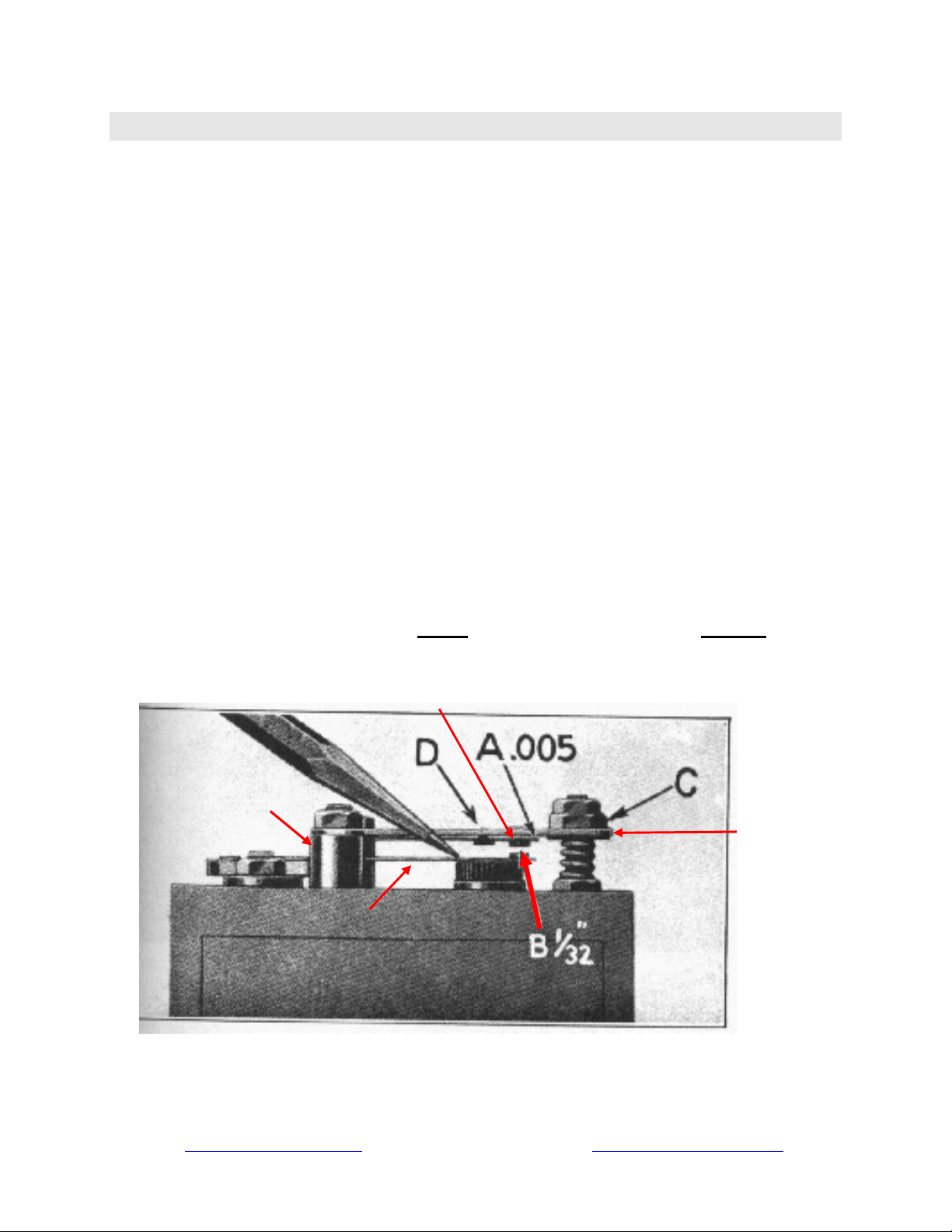
4.4.4 Coil Point Adjustment
The coil dwell time to fire is determined by many variables. The main variables are:
1. Vibrator Spring Tension
2. Cushion Spring Tension
3. Cushion Spring Travel
4. Point Gap
Attaining the desired dwell time to fire and firing consistency depends upon setting these 4
variables in the proper proportion with respect to each other. The ECCT coil test quickly
displays the Timing Error for a given set of these 4 variables. It is up to the operator to know
which of these variables to adjust to achieve the desired Timing Error and firing consistency.
Note that these 4 variables interact with each other which sometimes makes coil point adjustment
challenging to achieve the desired performance. Coil point adjustment requires patience and
experience for these reasons. It is highly recommended that new coil points be used when first
learning how to adjust and balance these 4 variables to achieve the desired result by avoiding
introduction of still more variables such as contact resistance and pitting. The next section
provides an introduction to the basics of coil point adjustment.

Model T Electronically Cranked Coil Tester
V12 ©2019 Mictel LLC
11
e-mail: m[email protected] www.modeltecct.com
IMPORTANT!
Small, gentle adjustments to these 4 variables make LARGE changes in
performance. It is easy to overshoot the desired adjustment goal if not careful.
4.4.5 Dwell Time to Fire Too Short
A coil firing too early results in negative timing error as illustrated in Figure 6.
Figure 6
Negative Timing Error
Figure 7
Correcting Negative Timing Error
Increase the coil dwell time to fire by tapping down gently on the rear of the vibrator spring as
illustrated in Figure 7.
Repeat Vibrator Spring adjustment as necessary until the coil Timing Error moves to the center,
0 deg position. Note that the Vibrator Spring metal support has a tendency to relax after
adjustment and may require re-adjustment after a few minutes.
Small taps on the Vibrator Spring support make Large changes in coil Timing Error so make
small taps and re-test the Timing Error to see how your adjustments affected performance. Refer
to the next section if you accidently over adjusted the Vibrator Spring to apply too much tension.
Negative Timing Error Move Timing Error to the Right by Tapping
Down on the Rear of the Vibrator Spring.

Model T Electronically Cranked Coil Tester
V12 ©2019 Mictel LLC
12
e-mail: m[email protected] www.modeltecct.com
4.4.6 Dwell Time to Fire Too Long
A coil firing too late results in positive timing error as illustrated in Figure 8.
Figure 8
Positive Timing Error
Figure 9
Correcting Positive Timing Error
Decrease the coil dwell time to fire by Prying up on the rear of the vibrator spring as illustrated
in Figure 9
Repeat Vibrator Spring adjustment as necessary until the coil Timing Error moves to the center,
0 deg position. Note that the Vibrator Spring metal support has a tendency to relax after
adjustment and may require re-adjustment after a few minutes.
A small pry up on the Vibrator Spring support makes Large changes in coil Timing Error so
make pry gently up and re-test the Timing Error to see how your adjustment affected
performance. Refer to the previous section if you accidently over adjusted the Vibrator Spring to
apply too little much tension.
Positive Timing Error Move Timing Error to the Left by Prying Up
Gently on the Rear of the Vibrator Spring.
Pry Up

Model T Electronically Cranked Coil Tester
V12 ©2019 Mictel LLC
13
e-mail: m[email protected] www.modeltecct.com
4.4.7 Double Sparking
Coil Double Sparking is a weak spark followed by a second weak spark. Double Sparking is
undesirable because of the weak spark may not have enough energy to ensure efficient
combustion and therefore is prone to fouling and misfire. The ECCT checks for Double
Sparking during the Coil and illuminates two (2) LEDs on the Timing Error display if Double
Sparking is detected as illustrated in Figure 10.
Figure 10
Coil Double Sparking
Figure 11
Correcting Double Sparking
4.4.8 Correcting Double Sparking
Double Sparking usually occurs if there is insufficient Cushion Spring tension necessary for the
upper point contact to remain in physical contact with the lower Vibrator spring contact as they
both travel down towards the coil core. Double Sparking can usually be corrected by increasing
the Cushion Spring tension. This is accomplished by prying up gently on the rear of the Cushion
Spring support with a small pliers or coil adjusting tool as shown in Figure 11.
4.4.9 Cushion Spring – Vibrator Spring Adjustment Interaction
Note that changing Cushion Spring tension will have the effect of reducing the dwell time to fire
so will also reduce the Timing Error (Move it to the Left). Timing Error can be moved back to
the center 0 deg position by increasing the Vibrator Spring tension as described in section 4.3.4
In some cases, it may be difficult to find the balance between Cushion Spring Tension and
Vibrator Spring tension. In that case, it may be helpful to try a different point contact gap.
Double Sparking is Indicated
by 2 LEDs Lit in the Display
Stop Double Sparking by Increasing Cushion
Spring Tension. This is Done by Gently Prying
UP on the rear of the Upper Bridge. NOTE:
A small adjustment makes a big difference.
Note: Timing Error may be Good but Spark is weaker than
usual so corrective action is necessary

Model T Electronically Cranked Coil Tester
V12 ©2019 Mictel LLC
14
e-mail: m[email protected] www.modeltecct.com
4.5 Multi-Spark Coil Firing Consistency Test
Coils that have passed the Capacitor and Coil tests with Good or Excellent results should then be
tested for Coil firing consistency with the ECCT Multi-Spark test. This test fires the coil 100
times at the rate of 2,000 RPM while monitoring the Dwell Time to Fire for each spark.
A properly adjusted coil is capable of a Timing Error variation of 0 deg +/-1 deg 95% of the
time or better. Points contacts that stick, are worn, oxidized, pitted or misadjusted Cushion
Spring tension will result in greater Timing Error variation indicating the coil is not operating as
consistently as it could and requires further action. It may be possible to clean or file the points
to improve firing consistency. Points that continue to exhibit wide firing variation should be
replaced.
4.5.1 Running the Multi-Spark Test
First run the Single Spark Coil test by pressing the ECCT test SELECT button until the
Coil/Dwell Test LED is illuminated. Press and release the TEST button and verify the single
spark coil test result is Good or Excellent. Repeating the Single Spark coil test multiple times
should produce the same result. If not, it is a good indication the results of the Multi-Spark firing
consistency test will also be poor.
Run the Multi-Spark test by pressing the ECCT Test SELECT button until the Multi-Spark test
mode LED is illuminated. Press and release the TEST button to start the Multi-Spark Coil Test.
The ECCT will begin firing the coil and monitoring the result of each spark.
4.5.2 Multi-Spark Test Result Display
Figures 12 and 13 illustrate acceptable Multi-Spark coil firing consistency results.
Figure 12 – Excellent Coil Firing Consistency Figure 13 – Good Coil Firing Consistency
Good Coil Firing Consistency – Some Firing
Variation but 95% within 0 +/-1 deg
Excellent Coil Firing Consistency – At least
85% of the firings occurred at 0 deg

Model T Electronically Cranked Coil Tester
V12 ©2019 Mictel LLC
15
e-mail: m[email protected] www.modeltecct.com
4.5.3 Multi-Spark Test Results
The ECCT illuminates a Timing Error LEDs if 5% or more of the firings occur in that timing
bin. A summary of the Multi-Spark coil test results is provided in Table 3 below.
Result Timing Error (Deg.)
Firing Consistency Firing Current
Excellent
0 At least 85% of firings Within ideal Range
Good 0 +/- 1 At least 95% of firings Within acceptable Range
Poor Outside 0 +/- 1 More than 5% of firings Outside acceptable Range
Table 3. Multi-Spark Test Results
IMPORTANT! – Good or Excellent Timing Error consistency may still result in an overall test
result of Poor if the coil firing current was outside the acceptable range. Repeat the Single Spark
coil test to confirm and correct this condition.
4.5.4 Poor Multi-Spark Test Results
Examples of poor Multi-Spark firing consistency test results
Figure 14 - Excessive Timing Error Variation Figure 15 – Excessive Timing Error Variation

Model T Electronically Cranked Coil Tester
V12 ©2019 Mictel LLC
16
e-mail: m[email protected] www.modeltecct.com
4.6 Magneto Test
The ECCT magneto test is an optional feature which tests the magnetic field strength of the
Model T magneto and displays the result similar to way the legacy St. Louis Magneto Tester
does; a recognized accurate method of assessing the magneto function. The Magneto test is
done while operating on battery by measuring the Magneto output at normal engine idle and
again at moderate engine speed with load applied to the Magneto. The change in Magneto
output voltage is directly proportional to the Magneto magnetic field strength.
4.6.1 Enabling the Magneto Test Feature
The ECCT Magneto test is an optional feature. The Red Magneto Test LED will only illuminate
when pressing the SELECT button if the Magneto test feature has been enabled on the ECCT.
The Magneto test feature can be enabled at time of purchase or any time after by purchasing a
software key that can be e-mailed and entered by the user using a PC or Laptop. For more
information about enabling the Magneto test feature, please visit www.modeltecct.com.
4.6.2 Running the Magneto Test
The ECCT Magneto test is run by following these steps:
1. Plug the 2.1mm x 5.5mm Magneto test cable into the Magneto input on the ECCT.
2. Connect the Red alligator clip to the Magneto output post and the Black alligator clip to
Unpainted Engine Ground or Frame (Not body which can be insulated from ground).
3. Power up the ECCT by pressing and holding the SELECT (Power) button for 5 seconds
4. Press the ECCT SELECT button until the Red Magneto Test LED is illuminated.
(Please refer to section 4.6.1 above if the Red Magneto Test LED does not illuminate).
5. Start the Model T engine operating on battery and let idle (500 – 700 RPM)
6. Press and release the ECCT TEST button, the Magneto Test LED will blink once.
7. Raise the engine idle within 10 sec until the Red Magneto Test LED begins flashing on
the ECCT then wait (~ 5 sec) for the test to complete. NOTE: The idle only needs to be
raised by about 500 RPM, No need to race the engine! The POOR LED will flash if no
magneto output is detected or does not increase with RPM after 5 seconds. Check test
cable connections to the magneto post and unpainted engine ground are good.
8. Lower the engine speed back to idle after the Magneto test results are displayed. The test
takes about 5 seconds to complete.
IMPORTANT! - Raising the engine speed to higher RPM will not affect the Magneto test
results. The engine speed only need be raised moderately until the Magneto test LED begins
flashing. The engine must be operating on Battery Power during magneto testing.

Model T Electronically Cranked Coil Tester
V12 ©2019 Mictel LLC
17
e-mail: m[email protected] www.modeltecct.com
4.6.3 Magneto Test Result Display
The ECCT Magneto test result display functions differently than previous tests. Two LEDs may
be lit indicating the reading is in between values. Examples of Magneto test results are provided
below for reference:
Figure 16 – Good Magneto Output Figure 17 – Good Magneto Output
Figure 18– Weak Magneto Output Figure 19 – Weak Magneto Output
Good Output - Magneto output strength is considered good if it is at or above the 1914 region
on the strength display as illustrated in figures 16 and 17.
IMPORTANT: Engine must be operating on battery during magneto testing
Both
LEDs
Lit

Model T Electronically Cranked Coil Tester
V12 ©2019 Mictel LLC
18
e-mail: m[email protected] www.modeltecct.com
Weak Output - Weak Magneto output is considered weak if the strength is just below the 1914
region. Both Good and Poor LEDs are illuminated to signal weak output as illustrated in figures
18 and 19.
Figure 20– Poor Magneto Output Figure 21 – No Magneto Output
Poor Output - Low Magneto output results in just the Poor LED being illuminated as illustrated
in Figure 20.
No Output - No Magneto output results in no strength LEDs illuminated and a flashing Poor
LED. Check the connections between the ECCT, Magneto post and Engine Ground. Make sure
the Alligator clips are firmly attached and making good electrical connection especially the
engine ground connection. Avoid attaching the alligator ground clip to painted surfaces which
can provide electrical isolation.
4.6.4 Magneto Test Results
A summary of the Magneto test results is provided in Table 4 below.
Result LEDs
Magneto
Strength
Comment
Excellent Excellent Magneto strength sufficient to properly operate coils
Good Good Magneto strength sufficient to properly operate coils
Good & Poor Weak Coil operation possible but may be marginal on magneto
Poor Poor Coil operation may not be possible on magneto
Poor Flashes 5 Times No Output No strength displayed, no magneto output detected
Poor Flashes 10 Times High Internal Resistance, > 3.5 Ohms. Check Mag post contact to
magneto coil
Table 4. Magneto Test Results
IMORTANT: Few, if any, Model T Magnetos will register in the EXCELLENT region.
Magnetic Field Strength Factor of GOOD is sufficient to properly operate Model T coils.
No Strength LED Illuminated
Flashing

Model T Electronically Cranked Coil Tester
V12 ©2019 Mictel LLC
19
e-mail: m[email protected] www.modeltecct.com
5ECCT - Advanced Features Software
The ECCT Advanced Features Software is an optional feature that provides additional test
capability including numerical and graphical display of test results. Detailed coil data and fine
tuning is possible with the software. The ECCT connects to a PC or Laptop computer running
Windows using a standard USB cable. The ECCT Software communicates with the ECCT
providing full control of all tests and displays the following information.
Capacitor Test:
•Capacitor value in microfarads, uF
•Leakage resistance in Ohms
Coil Test
•Coil dwell time to fire in milliseconds, ms
•Coil current at the time of firing in Amperes, A
•Spark Energy, mJ
•Coil Inductance in milli-Herrys, mH
•Precise timing error in crank shaft degrees at 1000 RPM
•Graphical display of dwell time to fire
Multi-Spark Coil Test:
•Coil firing consistency and repeatability
-Number of times the coil fires in each timing error range
-Ability to change the number of sparks fired from 2 to 250
-Ability to change the spark firing rate from 375RPM to 5000RPM
-Graphical display of statistical distribution of spark timing
Magneto Test: (if so equipped)
•Numerical display of the Magneto magnetic field strength factor
•Real time engine tachometer with numerical display of engine RPM
•Numerical display of the Magneto RMS output voltage under load and no load conditions
•Numerical display of the Magneto internal resistance
Other features include:
•Status window explaining test results and suggested actions
•Time and date stamp of all measurements
•Snap screen captures of test results to document performance and for future reference.

Model T Electronically Cranked Coil Tester
V12 ©2019 Mictel LLC
20
e-mail: m[email protected] www.modeltecct.com
Figure 22 ECCT Operation with Advanced Features Software
Table of contents