MID WEST PRODUCTS HT-10LRTA User manual

©2019 Mid West Products, Inc. -1- Form No. M53-1603
10 CU. FT. STEEL DUMP CART –MODEL HT-10LRTA
Owner’s Manual and Parts List
SAVE THIS MANUAL
You will need this manual for the safety instructions, assembly instructions and parts list. Put it in a
safe, dry place for future reference.
Additional Information/Link to PDF Copy of this Manual:

©2019 Mid West Products, Inc. -2- Form No. M53-1603
SAFETY INFORMATION
SAFETY RULES
Remember, any power equipment can cause injury if operated improperly or if the user does not
understand how to operate the equipment. Exercise caution at all times when using power equipment.
1. Read this Owner's Manual before attempting to assemble or operate the Cart.
2. Read the vehicle Owner's Manual and know how to operate your Tractor before using the Cart
attachment.
3. DO NOT at any time carry passengers in this Cart. It has not been designed to carry passengers.
4. Never allow children to operate the Tractor or the Cart attachment.
5. DO NOT allow adults to operate the Tractor or Cart attachment without proper instructions.
6. Always begin with the transmission in first (low)and gradually increase speed as conditions permit.
7. Tow the Cart at reduced speed over rough terrain and hillsides or near creeks and ditches to
prevent tipping over and loss of control. Do not drive too close to a creek or ditch.
8. Attaching this Cart may affect the vehicle braking and stability. Do not fill Cart to maximum weight
capacity without checking the capability of the towing vehicle to safely pull and stop with the Cart
attached.
9. Do not tow this Cart on highways or on public thoroughfares.
10. Maximum towing speed is 10 mph.
Look for this symbol to point out
important safety precautions. It
means: ATTENTION! Become
alert! Your safety is involved.
CAUTION: Vehicle braking and
stability may be affected with the
addition of an accessory or an
attachment. Be aware of changing
conditions on slopes.
The Dump Cart is designed for Garden and Yard use. DO NOT USE it for Commercial
or Industrial Purpose. The Manufacturer's Warranty DOES NOT COVER DAMAGES
through Accident, Abuse, Misuse, Commercial /Industrial Applications. The
Warranty also DOES NOT COVER any Losses, Injuries caused from Abuse, Misuse,
Commercial and/or Industrial Use.
To avoid Accidents and/or Injuries, please make sure there is no person around,
behind the Dump Cart when in use, especially when the Cart is used on hillsides and
ditches. The Cart may lose control in such severe conditions.

©2019 Mid West Products, Inc. -3- Form No. M53-1603
ASSEMBLY
The Cart requires a good deal of assembly, but with the right tools and careful reading of this Manual,
Cart assembly should be fairly routine. You will need a Regular Screwdriver, Pair of Pliers, Two 14
mm Open End Wrenches and Two 13 mm Open or Box End Wrenches (similar size Ratchet Wrenches
will speed assembly).
Part Numbers shown below refer to the Part Number Listing on Page 6.
It is recommended that all the parts be put out on a flat surface before beginning to assemble the Cart.
Check to see that all parts shown in this Manual are present (refer to Parts Illustrations and the Part
Number Listing on Page 6.
Step 1: Lay out the two Bottom Panels (#1) as shown in Figure 1 below. Attach the Front Cross
Brace (#2) to the Bottom Panels using 4 Bolts (#21), 4 Washers (#23) and 4 Nuts (#24).
Step 2: Connect the two Bottom Panels shown in
Figure 2 above using 4 Bolts (#21), 4
Washers (#23) and 4 Nuts (#24).
Step 3: Attach the Tongue Support (#3) to the
Bottom Panels using 2 Bolts (#), 2
Washers (#23) and 2 Nuts (#24). See
Figure 3 to the right.
Figure 1
Figure 2
Figure 3

©2019 Mid West Products, Inc. -4- Form No. M53-1603
Step 4: As shown in Figure 4 below, boltthe 2Wheel Axle Supports (#4) togetherusing 8 Bolts (#25),
8 Washers (#23) and 8 Nuts (#24).
Step 5: Bolt the Wheel Axle Supports (#4) to the
Bottom Panels (#1) using 8 Bolts (#21), 8
Washers (#23) and 8 Nuts (#24). See
Figure 5 to the right.
Step 6: As shown in Figure 6 below, insert the
Wheel Axle (#5) through the Wheel Axle
Support (#4). Install the 2 Wheel/Tire
Assemblies (#6) with Washers (#26) and
Cotter Pins (#27).
Step 7: As shown in Figure 7 to the right, insert the
Tongue Latch (#9) up through the opening
in the Hitch Tongue (#10). Using a Latch
Spacer (#8) on each side of the Tongue
Latch, bolt the Latch Spacer to the Hitch Tongue using Bolt (#29) and Nut (#30). Only hand
tighten this Bolt for now.
Step 8: Attach one end of the Latch Spring (#7) to the opening in the Hitch Tongue (#10) and the
other end to the top hole in the Latch Spacer (#8) as shown in Figure 7. With the Latch
Spring in place, tighten the Bolt described in Step 7.
Figure 4
Figure 5
Figure 6
Figure 7

©2019 Mid West Products, Inc. -5- Form No. M53-1603
Step 9: As shown in Figure 8 below, install the Hitch Pin Bracket (#11) by using 2 Bolts (#25), 2
Washers (#23), and 2 Nuts (#24) in the rear most two holes. The Hitch Pin (#28) fits in the
front hole, and is secured in place with a Cotter Pin (#27).
Step 10: Turn the Cart over onto its wheels. To the
rear portion of the Bottom Panels (#1),
attach the Rear Comer Brackets (#13) and
the Rear Cross Brace (#12), by using 4
Bolts (#21), 4 Washers (#23) and 4 Nuts
(#24). See Figure 9, top right.
Step 11: As seen in Figure 10 middle right,
assemble the left Side Panel (#14) using 2
Bolts (#21), 2 Washers (#23) and 2 Nuts
(#24). Insert bolts in the holes shown.
Step 12: See Figure 11 bottom right for bolt
positions. Finish bolting Rear Cross Brace
(#12) to Bottom Panels (#1) using 6 Bolts
(#21), 6 Washers (#23) and 6 Nuts (#24).
Figure 8
Figure 9
Figure 10
Figure 11

©2019 Mid West Products, Inc. -6- Form No. M53-1603
Step 13: Install the right Side Panel (#14) to the Bottom Panel (#1) as shown in Figure 12 below. Use
2 Bolts (#21), 2 Washers (#23), and 2 Nuts (#24) to attach the Side Panel.
Step 14: Secure each Side Panel (#14) by bolting a Rear Corner Brace (#15) to the outside of the
Side Panel. Use 5 Bolts (#21), 5Washers (#23) and 5 Nuts (#24) to secure each Side Panel.
Figure 13 above shows Rear Corner Brace being assembled to the left Side Panel. Follow
the same procedure to assemble Rear Corner Brace to the right Side Panel.
Step 15: Assemble the Front Panel (#16) to the Front Cross Brace (#2) and the two Side Panels (#14)
by using 12 Bolts (#21), 12 Washers (#23) and 12 Nuts (#24), Bolt positions are shown in
Figure 14 below.
Step 16: Assemble the two Front Corner Braces
(#17) to the corners of the Front Panel
(#16) and the Side Panels (#14) as
shown in Figure 15 to the right. For each
Front Corner Brace, use 2 Bolts (#21), 2
Washers (#23) and 2 Nuts (#24).
Figure 12
Figure 13
Figure 14
Figure 15

©2019 Mid West Products, Inc. -7- Form No. M53-1603
Step 17: Attach the two Tailgate Latches (#18) to
the inside of the Tailgate (#20) using 2
Bolts (#21), 2 Washers (#23) and 2 Nuts,
(#24) for each Tailgate Latch as shown in
Figure 16. Insert the two Tailgate Pins
(#19) through the two holes in inner
portion of the Tailgate, and secure the
Tailgate Pins by adding a Washer (#32)
and a Nut (#31) to the threaded portion.
The Tailgate is now ready to be put in
place on the Cart. Position the Tailgate
so that the two Tailgate Pins can be
dropped into the two holes on the Rear
Cross Brace (#12). The Tailgate Latches
can now be dropped over the open slots
in each Side Panel which will lock the Tailgate in place. Assembly of the Cart is complete.
Before using the Cart, make sure all hardware connections are tight.
PARTS LIST
Key
Part No.
Description
Qty
Key
Part No.
Description
Qty
1
234A1
Bottom Panel
2
17
234A17
Front Comer Brace
2
2
234A2
Front Cross Brace
1
18
234A18
Tailgate Latch
2
3
234A3
Tongue Support
1
19
234AI9
Tailgate Pin
2
4
234A4
Wheel Axle Support
2
20
234A20
Tailgate
1
5
234A5
Wheel Axle
1
21
234B1
M8x16 Truss Head Bolt
60
6
234A6
Wheel/Tire Assembly
2
22
234B2
M8x20
Truss
Head
Bolt
M8x20 Truss Head Bolt
2
7
234A7
Latch Spring
1
23
234B3
8mm Lock Washer
72
8
234A8
Latch Spacer
2
24
234B4
8mm Hex Nut
72
9
234A9
Tongue Latch
1
25
234B5
M8x20 Hex Head Bolt
10
10
234Al0
Hitch Tongue
1
26
234B6
20nun Flat Washer
2
11
234A11
Hitch Pin Bracket
1
27
234B7
3mm Cotter Pin
3
12
234A12
Rear Cross Brace
1
28
234B8
12.5x64 Hitch Pin
1
13
234A13
Rear Corner Bracket
2
29
234B9
M6x90 Hex Head Bolt
1
14
234A14
Side Panel
2
30
234B10
6mm Nylon Nut
1
15
234A15
Rear Comer Brace
2
31
234B11
6mm Hex Nut
2
16
234A16
Front Panel
1
32
234B12
6-8mm Flat Washer
2
Figure 16
Hardware included to assemble the Cart is shown below:
#21 M8x16 #22 M8x20 #23 8MM Lock #24 8MM #25 M8x20 #26 20MM #27 3MM Hair
Truss Head Truss Head Washer Hex Nut Hex Bolt Flat Washer Pin Cotter
234B1 234B2 234B3 234B4 234B5 234B6 234B7
#28 12.5x64 Hitch Pin #29 M6x90 Hex Head Bolt #30 6MM #31 6mm #32 6-8mm
234B8 234B9 Nylon Nut Hex Nut Flat Washer
234B10 234B11 234B12

©2019 Mid West Products, Inc. -8- Form No. M53-1603
PARTS DIAGRAM

©2019 Mid West Products, Inc. -9- Form No. M53-1603
OPERATION
1. Refer to the Vehicle Owner's Manual for
Instructions on safe operation on slopes.
2. For best handling and traction, distribute the
weight of the load evenly in the Cart.
3. Always test to make sure your Tractor has
adequate Towing and Braking Capabilities
whenever hauling a substantial amount of
weight in your Cart. Use extra caution when
operating on slopes.
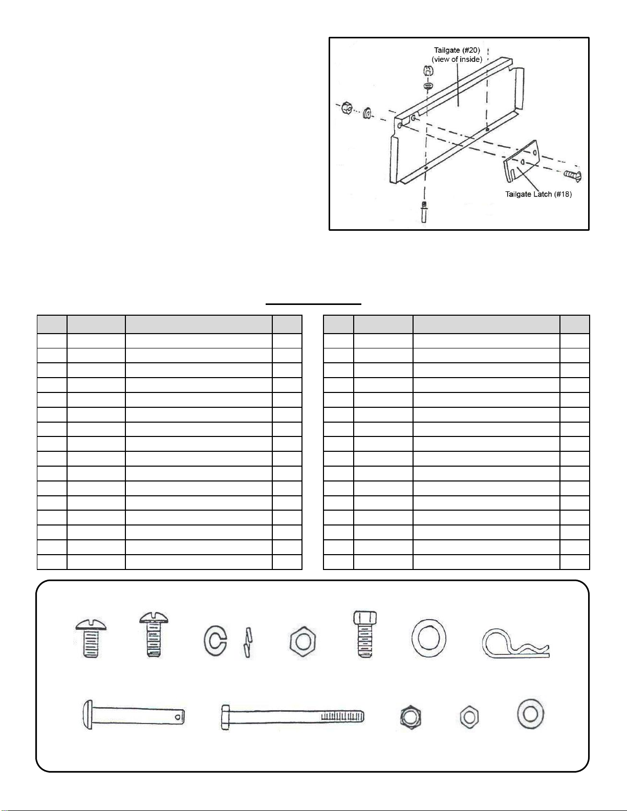
4. To dump material from the Cart, remove the
Tailgate by lifting it straight up and out from
between the Guides. Pull the Latch Lock
Lever forward to release the lock, the Cart
Bed will tilt backwards to empty its contents.
After emptying, push the front of the Bed
downward till the Latch Stand Bracket has
locked.
5. The maximum towing speed for this Cart is
10 mph.
MAINTENANCE
1. At the beginning of each season, Lubricate
the Latch, the Latch Pivot Bolt, and the area
of the Axle where the Drawbar Tongue
pivots with light machine oil.
2. Grease or Oil the Wheel Bearings
periodically. Use automotive wheel bearing
type Grease or 20 Weight Oil.
3. Keep Tires filled to the recommended Tire
Pressure of 20 psi.
Questions, problems, missing parts?
Before returning to your retailer contact:
Customer Service
GUARANTEE
The merchandise you have purchased from us has been carefully engineered and manufactured under
Mid West Products rigid quality standards and should give you satisfactory, dependable operation.
However, like all mechanical merchandise, it may occasionally require adjustment or maintenance.
Should you need technical assistance, please contact MID WEST PRODUCTS.
INSTRUCTIONS FOR ORDERING PARTS
(Minimum Parts Order Charge $20.00)
1. Address all parts orders or correspondence regarding customer service to one of the following:
Parts Dept.
Phone:
(937) 337-3641
Mid West Products, Inc.
P.O. Box 301
E-mail:
Phillipsburg, OH 45354
Website:
www.Mid-West-Products-Inc.com
2. Write your name and address plainly (print or type).
3. Explain where and how to ship.
4. Give model number of unit.
5. Give part number from parts list, as well as a description, including color, of the part and the quantity
you need.
6. Inspect all shipments you receive. If any parts are damaged or missing, file a claim with the carrier
before accepting.
7. If you are returning parts, be sure to include WITH THE SHIPMENT a list of the parts with your
name and address.
8. All orders for repair and replacement parts will be shipped when paid with Master Card, Visa, or
personal check/money order. Prices subject to change without notice.

©2019 Mid West Products, Inc. -10- Form No. M53-1603
OTHER LAWN & GARDEN TOOLS FROM
MID WEST PRODUCTS, INC.
40” Trailing Plug Aerator —HDP-40
•Heavy ¾" Tine Shaft w/32 14 Gauge Plugging Tines - 4 Welded Tine
Sections Rotate Independently on Turns.
•Wide 40" Working Width Plug Aerator.
•3" Penetration Depth.
•Recommended Load Capacity: 175 Lbs. *Maximum
•Single Steel Center Lift Lever Adjustable from the Tractor Seat.
•Overall Dim: 49" L x 50" W x 33" H
38” Deluxe Trailing Lawn Sweeper — HDT-38
•Semi-Pneumatic, Ribbed Tread Rubber Tires mounted on Precision Die
Cast Aluminum Wheels.
•Ball Bearing Rear Casters Provide easy Mobility.
•Patented Rear-Dump w/Centered Pull Cord Dumps from Tractor Seat.
•Wind Apron protects 12 Bushel Hamper Capacity.
•Brush Height Control.
•Overall Dim: 70” L x 45” W x 40” H
45” Trailing Lawn Sweeper — MH-4451
•Semi-Pneumatic, Ribbed Tread Rubber Tires mounted on Precision Die
Cast Aluminum Wheels.
•Ball Bearing Rear Casters Provide easy Mobility.
•Patented Rear-Dump w/Centered Pull Cord Dumps from Tractor Seat.
•Wind Apron protects 15 Bushel Hamper Capacity.
•Brush Height Control.
•Overall Dim: 44” L x 50” W x 35” H
40” Trailing Dethatcher — HDR-40
.
•Heavy Gauge Steel Chassis.
•Individually Flexing Tine Tips - 3/16” Diameter with Triple Coil Strength.
•Wide Working Width Dethacher with 8” Transport Wheels.
•Adjustable Hitch for Various Rider Heights.
•No tool Assembly.
•Overall Dim: 49” L x 43” W x 12” H
Table of contents
Other MID WEST PRODUCTS Outdoor Cart manuals