Midcontinent MD23-215 User manual

User Guide
For
MD23-215
Multifunction Digital
Counter Drum Altimeter
powered by
Rev
Date
Detail
Approved
1
12/09/2021
Initial release.
BAW
This manual provides information intended for use by persons who, in accordance with current
regulatory requirements, are qualified to install this equipment. It is a supplement to the MD23
Installation Manual and Operating Instructions, p/n 9019161.
If further information is required, please contact Mid-Continent Instruments and Avionics.
Mid-Continent Instruments and Avionics Mid-Continent Instrument Co., Inc.
dba Mid-Continent Instruments and Avionics
User Guide UG215 9400 E. 34th Street N.
Revision 1 Wichita, KS 67226 USA
ph (800) 821-1212
www mcico.com

MD23-215
User Guide
Mid-Continent Instruments and Avionics 2 User Guide UG215, Revision 1
December 9, 2021
1.1 INTRODUCTION
The model MD23-215 multifunction digital counter drum altimeter is a standard 2-inch (2-¼”)
panel-mounted instrument that displays and offers several altitude related functions. Based on
Mid-Continent Instruments and Avionics patented FLEXTM Custom Function Display, this FAA
and EASA TSO-approved instrument brings a highly capable and modern addition to the cockpit
to display required information and provide useful supplementary functions.
This User Guide is a supplement to the Installation Manual and Operating Instructions (IM),
MCIA part number 9019161. The IM contains all information associated with the standard
product, including installation procedures, product specifications, operating instructions,
certification data, and maintenance requirements. This User Guide provides additional
information associated with the specific features of the multifunction digital counter drum
altimeter. It addresses product identification, electrical pinout, initial configuration setup, and in-
flight user operation.
1.2 PRODUCT IDENTIFICATION
Each MD23 is comprised of certified hardware and certified software. Within the context of the
certified software is a set of data items that can configure and customize the behavior of the unit.
This set of data is referred to as a Custom Instrument Definition, or a CID file. The CID file for
this instrument is pre-loaded and may be available for future updates via a standard USB flash
drive through the programming port on the rear of the unit.
A unique CID number has been assigned specifically to this application. The CID is identified by
its two-digit number and an alphabetic character representing the CID version, starting with “A”.
The identification of the hardware, software, and CID configurations are listed below. Both the
software version and the CID can be viewed on the Introduction Screen during the first few
seconds of applying power to the unit. This information can also be accessed on the Info page of
the Options Menu during Flight Mode.
PRODUCT FUNCTION
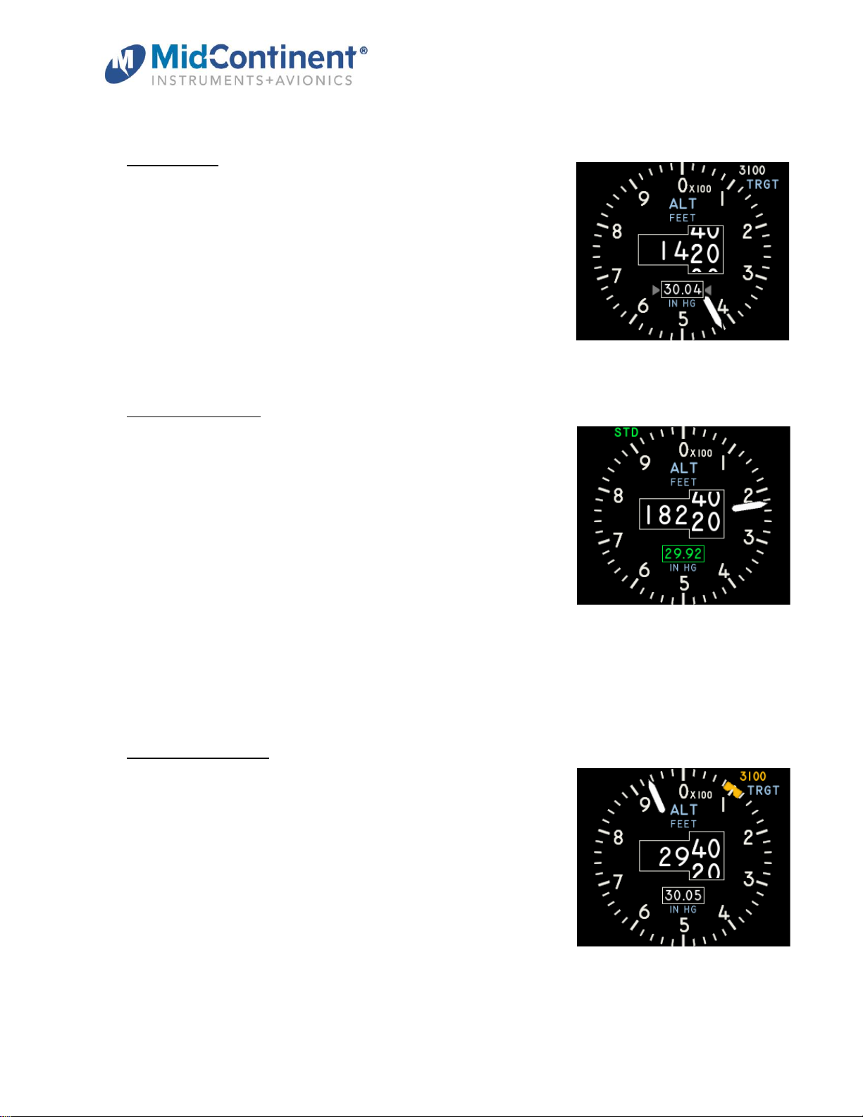
The Multifunction Digital Counter Drum Altimeter primarily provides pressure altitude above sea
level up to 55,000 feet. Altitude is numerically presented as a scrolling value in a central window
(the ‘counter drum’) with 20-foot resolution. A single pointer also provides visual analog
representation with each rotation representing 1000 feet indication and 20-foot resolution. Altitude
can be adjusted with the barometric pressure manually or using an externally synchronized
source. Units are configurable for feet or meters and inches of mercury, millibars or hectopascals.
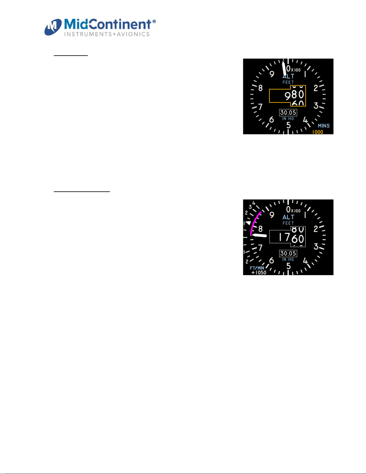
Other features include a vertical speed indicator, a vertical speed trend line, a Standard baro
setting, a Target Altitude bug, and a minimum altitude alert setting. The altimeter can provide an
encoding feature, with outputs in ARINC 429 and Gillham (or ‘gray’) code.
Unit Versions
Hardware Part Number
Software Version
CID
6420023-2
1.0.2, or later
15A, or later

MD23-215
User Guide
Mid-Continent Instruments and Avionics 3 User Guide UG215, Revision 1
December 9, 2021
2.1 CONNECTOR PINOUT
For standard pre-installation and installation instructions, including location, cable harness
assembly, pneumatic inputs (if applicable), mounting, and others, please refer to the IM.
Pinout identification specific to this CID is listed in the table below. A brief description is provided.
Further definition of the inputs and outputs should be documented in the technical requirements
and/or statement of work and are not provided within this User Guide.
Connector Pinout
Pin
Description
Function
1
Ground
Power return; connect to a/c ground
2
ARINC Out (A)
Labels 203, 204, 212, 217, 234, 235
3
ARINC Out (B)
(paired with pin 2)
4
Dimmer Input
5, 14, or 28VDC input (if used)
5
ARINC In (A)
Labels 234, 235
6
Reserved
7
Reserved
8
Reserved
9
Reserved
10
Reserved
11
C4
Gillham code, bit 0
12
C1
Gillham code, bit 2
13
B2
Gillham code, bit 4
14
ARINC In (B)
(paired with pin 5)
15
A2
Gillham code, bit 7
16
Reserved
17
Reserved
18
Reserved
19
Power Input
+10-32VDC
20
C2
Gillham code, bit 1
21
B4
Gillham code, bit 3
22
B1
Gillham code, bit 5
23
A4
Gillham code, bit 6
24
A1
Gillham code, bit 8
25
D4
Gillham code, bit 9
26
Reserved
Table 1 Unit Connector Pin Identification
Pneumatic Ports
Port
Description
Function
S
Static / Absolute
External Static Pressure
P
Pitot / Differential
Not used

MD23-215
User Guide
Mid-Continent Instruments and Avionics 4 User Guide UG215, Revision 1
December 9, 2021
3.1 CONFIGURATION AND SETUP
Enter Configuration Mode by pressing and holding the Control Knob while applying power to the
unit. For configuration and setup of standard unit functions, including dimming control options
and dimming curve definition, please refer to the IM.
Configuration settings specific to this unit are found within the User Configuration menu option.
The User Configuration items include two functions:
3.1.1. ALTITUDE UNITS
Within the User Configuration Menu, the Altitude Units can
be set without leaving the page. With the Altitude Units
option highlighted, the current selection is shown to the right
in gray. By selecting the Altitude Units option, the units to
the right become active and additional options are
displayed. The MD23 can be set to display altitude in either
Feet or Meters.
Turn the Control Knob to highlight the preferred units and
press to select it. The cursor will return to the Altitude Units
option in the menu list and the selected option will be shown in gray to the right.
3.1.2. CALIBRATE ALTITUDE
Use the Calibrate Altitude process if the displayed altitude
does not match a known altitude reference. When selected,
the Calibrate Altitude option opens a new page. Allow the
unit five to ten (5-10) seconds to settle and display the
currently reported altitude. The altitude will be shown in the
units that are currently configured. The calibration page
provides instructions to compare the known reference at
standard barometric pressure. The message regarding the
standard barometric pressure reference will change
depending on the currently configured Baro units (either
29.92 In Hg or 1013 mBar) .
Turn the Control Knob until the altitude value matches the known external reference.
Pressing the Control Knob will confirm the calibration and exit the page back to the User
Configuration Menu.
3.1.3. EXIT
Highlighting and selecting the Exit menu item will close the User Configuration Menu and
return to the Configuration Menu.

MD23-215
User Guide
Mid-Continent Instruments and Avionics 5 User Guide UG215, Revision 1
December 9, 2021
4.1 OPERATION
For operation of standard unit functions, including the Options Menu, manual brightness control,
Info page, and others, please refer to the IM.
4.1.1. PRIMARY DISPLAY PRESENTATION
In Flight Mode, the display is presented as shown in the example figures below.
Power on screen Normal Operation
(example)
Primary Function elements are defined as follows:
•Dial: Numbers from 0 to 9, clockwise with major grads that represent 100 units (feet or
meters) and minor grads that represent 20 units.
•Pointer: Rotates clockwise with increasing altitude, counter-clockwise with decreasing
altitude. If the altitude is below zero, the pointer will remain at zero and both the pointer
and altitude value will turn amber. The pointer will not appear with invalid altitude (out of
range or unit failure).
•Counter Drum window: Displays the altitude as a numeric value. The tens value is
displayed in an expanded window with rolling numbers representing every 20 units. The
hundreds, thousands, and ten-thousands digits will change with a similar rolling action at
each increment. Invalid altitude will be represented with red dashes (- - - - -). Negative
altitude will be represented with amber numbers and a negative sign (-) in the ten-
thousands digit location.
The altitude units, as selected in the Configuration Mode, is displayed above the window.
•Barometric Pressure window: Current and correct altitude can only be displayed when
adjusted in accordance with the existing barometric pressure conditions. To do this,
simply turn the Control Knob to enter the current barometric pressure. The range is from
27.50 to 31.50 In Hg or 930 to 1070 millibar (mbar)/hectopascals (hPa), depending on
the selected units as displayed in blue below the Baro window.

MD23-215
User Guide
Mid-Continent Instruments and Avionics 6 User Guide UG215, Revision 1
December 9, 2021
4.1.2. SECONDARY DISPLAY PRESENTATION
Secondary Function elements are defined as follows. Further details about each secondary
function can be found in 4.1.4.
Display of All Secondary Functions
•Standard Baro reset function (STD). Status is displayed in the upper left corner.
•Altitude Target. The Target status and value are displayed in the upper right corner.
•Minimum threshold. The MINS status and value are displayed in the lower right corner.
•Vertical Speed. The vertical speed scale and indicator are found along the left edge of
the display. The numeric value and units of vertical speed are in the lower left corner.
•Vertical Speed Trend Indicator. The VS trend indicator is shown in magenta along the
circumference of the dial, emanating clockwise or counter-clockwise from the current
altitude position of the pointer.
4.1.3. USER OPTIONS
Pressing and holding the Control Knob for three (3) seconds
will activate the Options Menu. The manual brightness
adjustment and info page are described in the IM. The
Options Menu or User Options items will close and return to
the active display after ten (10) seconds if no knob activity is
recorded.
When highlighted and selected, the User Options item will
open a new page and display the options available to the
user during Flight Mode. The User Options menu is where
the Secondary Functions can be turned on, off, or set to their desired mode. The list of
features are provided in 4.1.2 and shown in the image.
Highlight and select Exit to return to the Options Menu or simply wait five (5) seconds and the
unit will return to the active Flight Mode display.

MD23-215
User Guide
Mid-Continent Instruments and Avionics 7 User Guide UG215, Revision 1
December 9, 2021
4.1.4. ALTIMETER FUNCTIONS
BARO SYNC
The barometric pressure setting can be synchronized with an
external system (such as the primary avionics) via ARINC 429.
When available, two small gray triangles will appear next to the
Baro window. The baro value will follow and match the external
input and turn green while changing, and back to white when
stable. The baro setting can be manually changed at any time
by simply turning the Control Knob. The gray arrows will be
removed. If the external sync signal is still valid and available, it
will revert back to sync mode when the external input value changes.
STANDARD BARO
The user can change the barometric pressure value directly to
standard baro (29.92 inHg or 1013 mBar/hPa) using the
Standard feature. By pressing the Control Knob once, the STD
annunciation will be highlighted from gray to magenta. By
turning the Control Knob left or right and pressing when ON is
displayed, the baro will change to standard value.
This feature can be turned off in the User Options Menu or be
set to Auto. In Auto mode, the baro will automatically revert to
standard baro and the STD label will change from white to
green when the altitude ascends past 18,000 feet (FL 180; or equivalent meters). In auto mode,
the STD label will turn yellow when the aircraft descends below 18,000 feet, to indicate the need
to adjust the baro pressure to the applicable value. Manually adjusting the baro with the Control
Knob, or through the external sync will immediately take the unit out of Standard Baro mode.
ALTITUDE TARGET
The user can use the Altitude Target feature to set a point of
interest as a reminder or altitude acquisition value. The Target
feature can be turned on or off in the User Options Menu.
When on, the Target Value can be set by pressing the Control
Knob until the TRGT annunciator turns magenta.
Once the TRGT feature is active, turning the Control Knob left
or right will change the target value and rotate the magenta
Target Bug around the dial to its corresponding position. The
Target value has a resolution of 100 units. Once active, the bug
is only visible on the dial when the current altitude is within 800 units of the target. The bug is
cyan until the current altitude is within 200 units, then the bug and the target value will turn
amber. When within 50 units, the bug and target value will turn green.

MD23-215
User Guide
Mid-Continent Instruments and Avionics 8 User Guide UG215, Revision 1
December 9, 2021
MINIMUMS
A Minimum Altitude Alert can be set for approaches or related
reminders. The Minimums (MINS) Alert feature can be turned
on or off in the User Options Menu. When on, the Minimum
Value can be set by pressing the Control Knob until the MINS
annunciator turns magenta.
Once the MINS feature is active, turning the Control Knob left
or right will change the minimum value. Once set, the MINS
alert will activate when the aircraft descends past the set value
after being above it. When activated, the border around the
main altitude value (the ‘counter drum window’) will turn amber, along with the MINS numeric
value. The alert will stay active until ascending 50 units above the minimum value or until the
unit is power cycled.
VERTICAL SPEED
Vertical Speed can be displayed in two ways. As an analog
and digital vertical speed indicator (VSI) or as a dynamic
vertical trend line. Both the VSI and the Trend features can be
turned on or off independently under the VSI option in the User
Options Menu (VSI/TREND/BOTH/OFF). When on, neither
feature has any further user options.
The VSI feature provides an analog scale from -2000 to +4000
feet per minute (or -10 to +20 meters per second) and a digital
readout of the vertical speed up to ±9000 feet per minute (or
equivalent meters per second). The VSI units are determined by the configured altitude units
(feet or meters).
The vertical trend line is representative of a 6-second trend. The end of the magenta arc
predicts the aircraft’s altitude in six seconds given the current rate of climb or descent.

MD23-215
User Guide
Mid-Continent Instruments and Avionics 9 User Guide UG215, Revision 1
December 9, 2021
5.1 CONFORMANCE
For standard conformance items such as qualification levels and software updates, please refer
to the IM.
5.1.1 INSTRUCTIONS FOR CONTINUED AIRWORTHINESS
For this application, the MD23 is configured to accept and display data associated with a
static pressure source. Some aviation regulations may apply to inspect and test for accuracy
on a regular basis. (for example, 14 CFR §91.411 for altimeters) Please identify and/or refer
to the appropriate maintenance procedures for your aircraft in the pilot operating handbook or
flight manual supplement.
5.1.2 COMPONENT MAINTENANCE AND REPAIR
No periodic scheduled maintenance or calibration is necessary for continued airworthiness of
the MD23 Custom Function Display, unless specified in the aircraft maintenance procedures,
as referenced above in 5.1.1.
The unit display can be cleaned using a lint-free cloth moistened with water. No chemicals
should be used to clean the display.
If the unit fails to perform to specifications, the unit must be removed and serviced by Mid-
Continent Instruments and Avionics or their authorized designee. Other than software version
updates or in-field calibration, there are no repairable parts or processes available to be
performed in the field.
Table of contents
Other Midcontinent Measuring Instrument manuals
Popular Measuring Instrument manuals by other brands

VOLTCRAFT
VOLTCRAFT CO-500 operating instructions

HSS Hire
HSS Hire 49711 Operating & safety guide

biochrom
biochrom Libra S21 user manual

Promet
Promet FiBO 250 quick start guide

Agilent Technologies
Agilent Technologies Agilent 8163A Programming guide

BC Group International
BC Group International BC Biomedical SA-2600 user manual

Campbell
Campbell cs215 instruction manual

Delta
Delta DVP04TC-H2 instruction sheet

MONARCH INSTRUMENT
MONARCH INSTRUMENT Nova-Pro 100 instruction manual

PCB Piezotronics
PCB Piezotronics CS625B11 Installation and operating manual

EG&G
EG&G ORTEC 553 Operating and service manual

MULTISPAN
MULTISPAN MS-1208A user manual