Middle Atlantic Products VDM Series User manual

I-00806 Rev B
Instruction Sheet
VDM Series
Full-Motion Display Mount
Thank you for purchasing the Vision Display Full-Motion display mount.
Please read these instructions thoroughly before installing or assembling these products.
• Ideal for corner mount installs and single-person servicing
• Cable management built into arms to help maintain signal integrity and aesthetics
• Safety locking features keep the display securely mounted
• Arm extends 20”
• VESA Capability:
VDM-200-M 75x75mm - 200x200mm
VDM-400-M 75x75mm - 400x400mm
THANK YOU
PRODUCT FEATURES
VDM-200-M
VDM-400-M

Page 2
IMPORTANT SAFETY INSTRUCTIONS / INSTRUCTIONS IMPORTAANTES SUR LA SÉCURITÉ
SAVE ALL INSTRUCTIONS / CONSERVER CES INSTRUCTIONS
CAUTION/ATTENTION and the exclamation point within an
equilateral triangle is intended to alert the user to the possibility of
damaging or destroying the equipment if the instructions are not
followed.
Attention et le point d'exclamation dans un triangle équilatéral est
destiné à alerter l'utilisateur de la possibilité d'endommager ou de
détruire l'équipement si les instructions ne sont pas suivies.
WARNING/AVERTISSEMENT and the exclamation point within an
equilateral triangle is intended to alert the user to the possibility of
serious injury or death if the instructions are not followed.
Avertissement et le point d'exclamation dans un triangle équilatéral
est destiné à alerter l'utilisateur de la possibilité de blessures
graves ou la mort si les instructions ne sont pas suivies.
WARNING: Failure to read, understand and follow the following information can result in seri-
ous personal injury, damage to the equipment or voiding of the warranty.
AVERTISSEMENT: Ne pas lire, comprendre et suivre les informations suivantes peut entraîner
des blessures graves, des dommages à l'équipement ou de la nullité de la garantie.
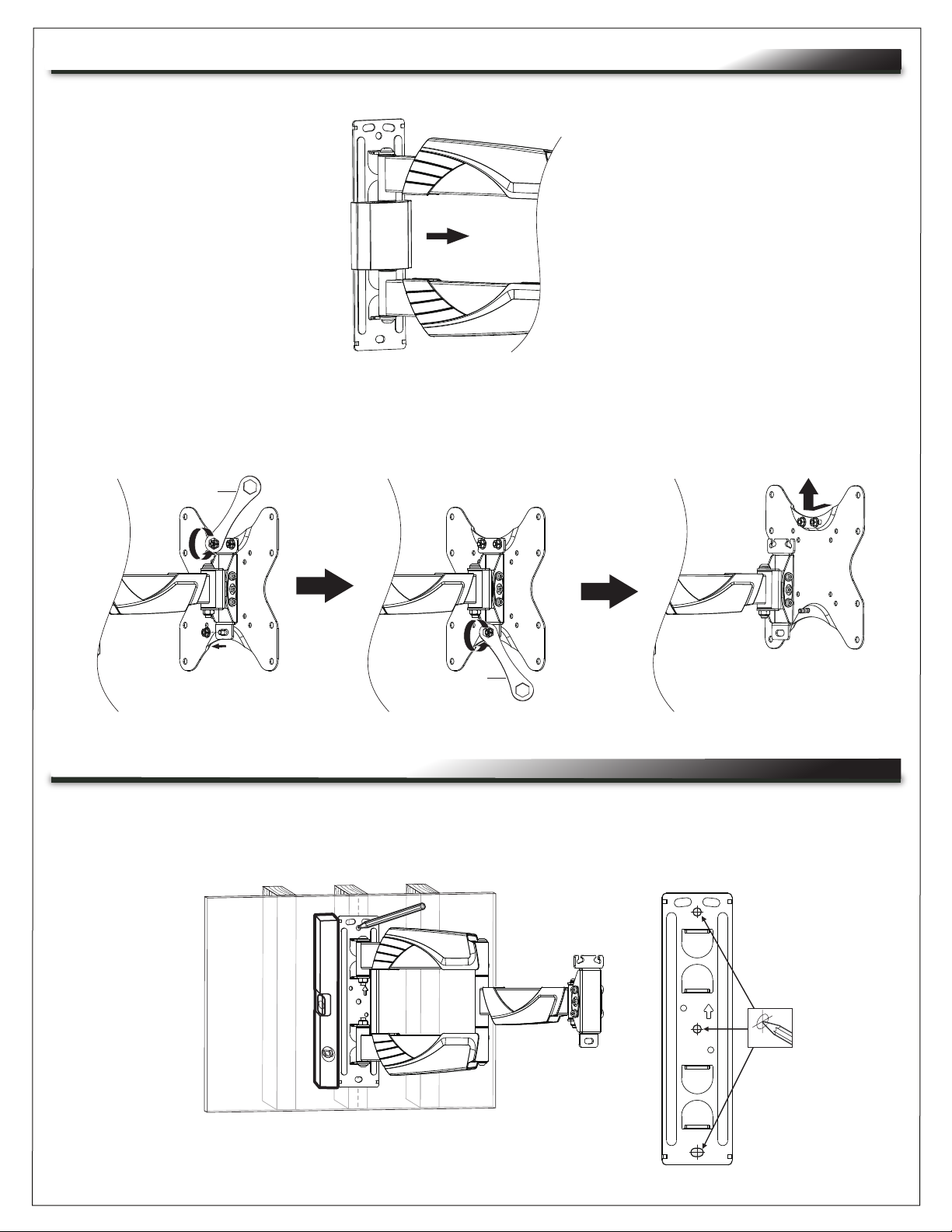
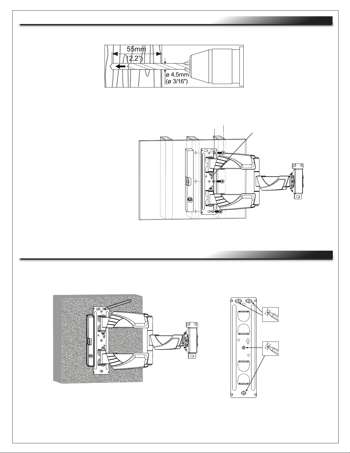
WARNING: Failure to provide correct structural strength for the component may result in seri-
ous personal injury or damage the equipment. The 2x4 stud wall to which the component is
being attached may have a maximum drywall thickness of 5/8” (1.6 cm).
AVERTISSEMENT: Le défaut de fournir une résistance structurelle correcte pour le composant
peut entraîner des blessures graves ou endommager l'équipement. Le goujon de 2x4 auquel le
composant mur est connecté peut avoir un maximum de 1.6 cm (5/8”) d'Épaisseur cloison
sèche.
WARNING: Exceeding the weight capacity may result in personal injury or equipment damage.
The combined weight of all components attached to the mount must not exceed weights listed
on page 3.
AVERTISSEMENT: Dépasser la capacité de poids peut entraîner des blessures ou des dom-
mages matériels. Le poids combiné de tous les composants reliés au support de montage ne
doit pas dépasser les grammages indiqués à la page 3.
WARNING: Be aware of pinch points and do not place fingers in between moving parts.
AVERTISSEMENT: Soyez conscient des points de pincement et de ne pas placer les doigts
entre les pièces mobiles.
WARNING: Use this product for its intended use and only use attachments recommended by
the manufacturer.
AVERTISSEMENT: Utilisez ce produit pour son utilisation prévue et utiliser uniquement les
accessoires recommandés par le fabricant.
WARNING: Do not use a damaged product. Return damaged products to a qualified service
center for repair.
AVERTISSEMENT: Ne pas utiliser un produit endommagé. Retour produits endommagés à un
centre de service qualifié pour la réparation.
WARNING: Not intended for outdoor use.
AVERTISSEMENT: Non destiné à une utilisation en extérieur.

Page 3
WEIGHT RATINGS
Model Weight Rating
VDM-400-M 50 lbs. Maximum Total Rated Load
VDM-200-M 50 lbs. Maximum Total Rated Load
REQUIRED TOOLS
• #2 Phillips Screwdriver
• Level
• Power Drill
• Protective Eyewear
• 3/16” Wood Bit or 3/8” Masonary Bit
• Hammer
• 10mm Socket
• Hex Wrench (Supplied)
• 4mm Hex Key (Supplied)
WARNING: Use tools with caution and follow all necessary safety protocols.
AVERTISSEMENT: Utiliser des outils avec prudence et suivre tous les protocoles de sécurité
nécessaires.
(1)
Display Mount
(A)
SUPPLIED COMPONENTS
(2)
Wall Cover
(B)
(2)
Left Display
Bracket
(400 Only)
(C)
(2)
Right Display
Bracket
(400 Only)
(D)

Page 4
SUPPLIED COMPONENTS (CONTINUED)
(8)
Display Bracket
Screws
(400 Only)
(N)
(4)
M4 x 20
(M-B)
M5 x 30
(M-D)
M6 x 20
(M-F)
M6 x 30
(M-G)
M5 x 12
(M-C)
(4) (4)
M6 x 12
(M-E)
(4) (4) (4)
M4 x 12
(M-A)
Display Mount Screws
M8 x 16
(M-H)
(4)
M8 x 20
(M-J)
(4)
(4) M8 x 40
(M-K)
(4)
(1)
Hex Wrench
(E)
(4)
Hex Head Screw
(G)
(4)
Wall Anchor
(H)
(4)
Washer
(M)
(8)
Small Spacer
(K)
(4)
Large Spacer
(400 only)
(L)
(1)
Hex Key
(F)
(4)
M5 Washer
(P)
(4)
M8 Washer
(R)
(1)
Proximity Mounting
Plate Kit
(400 only)
(S)

FIGURE A
FIGURE B
1. Locate the stud center where you wish to locate your mount arm.
2. Use a level beside the mount arm to mark 3 holes for the stud. (FIGURE C)
FIGURE C
REMOVING DISPLAY MOUNT ARM FROM HORIZONTAL DISPLAY SUPPORT
ATTACHING MOUNT ARM TO A STUD
1. Carefully remove the center wall cover as shown. (FIGURE A)
2. Use supplied hex wrench (E), loosen the top two flange nuts and remove the bottom nut. Tilt the
bottom of display support out and slide up to remove it from the display mount arm as shown.
(FIGURE B)
Mark 3 Holes
E
E
Page 5

1. Use a level beside the mount arm to mark 4 holes on the concrete where you wish to locate
your mount arm. (FIGURE F)
FIGURE E
FIGURE F
FIGURE D
3. Use a 3/16” (4.5 mm) bit to drill pilot holes into the markings to a 2.2” (55 mm) depth. (FIGURE D)
4. Use (3x) hex head screws (G) and (3x) washers (M) to attach the mount arm to the studs as
shown. (FIGURE E)
ATTACHING MOUNT ARM TO A CONCRETE WALL
ATTACHING MOUNT ARM TO A STUD (CONTINUED)
Mark 4 Holes
G
M
Page 6
Arrow must face up

Page 7
FIGURE G
2. Use a 3/8” (10 mm) bit to drill pilot holes into the markings to a 2.4” (60 mm) depth.
ATTACHING THE MOUNT ARM TO A CONCRETE WALL (CONTINUED)
FIGURE H
3. Use (4x) wall anchors (H), (4x) hex head screws (G), and (4x) washers (M) to attach the mount
arm to the wall as shown. (FIGURE G)
To prevent anchors from stripping, only use a hand tool to install screws.
G
M
H
1. Attach (2x) top and bottom wall covers (B) and the center wall cover to the mount arm as shown.
(FIGURE H)
ATTACHING THE WALL COVERS TO THE MOUNT ARM
NOTE: Wall anchors may
require a hammer
to install.
Arrow must face up
60mm
(2.4")
ø 10mm
(ø 3/8")
B
NOTE: To prevent anchors from
stripping, only use a hand
tool to install.

Page 8
STOP
The VDM-400-M display mount is supplied with a Proximity
Series Mounting Plate PRX-MP-9X12. Before installing display
mounting brackets to your display, follow the supplied
mounting plate installation instructions I-00804 to find the best
location for mounting your plate.

FIGURE J
Page 9
N
N
1. Use a Phillips screwdriver and (8x) display bracket screws (N) to attach the (2x) left display
brackets (C) and (2x) right display brackets (D) into one of the following configurations on the
display support. (FIGURE J)
Attaching to a Flat Back Display
1. Use (4x) washers (P or R) and (4x) display mount screws (M-A - M-K) to match the correct screw
depth for your display and attach the display brackets on the displaysupport to your display.
(FIGURE K)
ATTACHING THE MONITOR SUPPORT TO THE DISPLAY (400 ONLY)
ATTACHING DISPLAY BRACKETS TO DISPLAY SUPPORT (400 ONLY)
FIGURE K
M-A - M-K
P or R

Page 10
Attaching to a Raised or Recessed Back Display
1. Use (4x) washers (P or L), spacers (K or L) as desired, and (4x) display mount screws (M-A - M-K)
to match the correct screw depth for your display and attach the display brackets on the display
support to your display ensuring screw does not bottom out in mounting hole, or damage to display
may occur. If you feel resistance, stop immediately and try a shorter screw. If supplied screws are
still too long, use supplied spacers to take up slack.(FIGURE L)
ATTACHING DISPLAY SUPPORT TO DISPLAY (400 ONLY, CONTINUED)
FIGURE L
Attaching to a Flat Back Display
1. Use (4x) washers (P or R) and (4x) metric screws (M-A through D) to match the correct screw
depth for your display and attach the display support to your display ensuring screw does
not bottom out in mounting hole, or damage to display may occur. If you feel resistance, stop
immediately and try a shorter screw. If supplied screws are still too long, use supplied spacers to
take up slack. (FIGURE M)
ATTACHING DISPLAY SUPPORT TO DISPLAY (200 ONLY)
FIGURE M
TV
TV
TV TV
P or R
M-A - M-K
P or R
M-A - M-K
(P or R)
M-A - M-K
K or L K and L

Page 11
1. Carefully use the top bolts (with the flange nuts attached) to tilt and hook the display support
into the top slots on the end of the arm as shown. (FIGURE P)
ATTACHING DISPLAY SUPPORT TO MOUNT ARM
FIGURE P
NOTE: 200 Mount Pictured
ATTACHING DISPLAY SUPPORT TO DISPLAY (200 ONLY, CONTINUED)
Attaching to a Recessed Back Display
1. Use (4x) washers (P or R), small spacers (K) as desired, and (4x) display mounting screws
(M-A - M-K) and attach the display support to your display ensuring screw does not bottom out
in mounting hole, or damage to display may occur. If you feel resistance, stop immediately and try
a shorter screw. If supplied screws are still too long, use supplied spacers to take up slack.
(FIGURE N)
FIGURE N
TV
TV
TV TV
M-A - M-K
P or R
K
K
P or R
M-A - M-K

Page 12
ATTACHING DISPLAY SUPPORT TO MOUNT ARM (CONTINUED)
FIGURE R
FIGURE T
2. Use a level on top of the display and the supplied hex wrench (E), make any fine adjustments and
tighten the top flange nuts as shown. (FIGURE R)
3. Attach and tighten the lower flange nut as shown. (FIGURE T)
E
E

Page 13
FIGURE V
F
1. Loosen the upper levers and use the hex key (F) to loosen the hex cap screw to adjust the tilt on
your display as shown. Once desired tilt angle is achieved, retighten wing screw and hex cap screw to
lock display in position. (FIGURE V)
ADJUSTING THE TILT
1. Remove display mount arm covers, run cables through the cover as desired, and then reattach
the arm covers. (FIGURE U)
CABLING
NOTE: 200 Mount Pictured

Page 14
For warranty information, refer to www.middleatlantic.com/terms.
Corporate Headquarters
Corporate Voice: 973-839-1011 - Fax: 973-839-1976 / International Voice: +1 973-839-8821
Fax: +1 973-839-4982
Middle Atlantic Canada
Voice: 613-836-2501 - Fax: 613-836-2690
Factory Distribution
USA: NJ - CA - IL Canada: ON - BC
At Middle Atlantic Products we are always listening. Your comments are welcome.
Middle Atlantic Products is an ISO 9001 and ISO 14001 Registered Company.
WARRANTY
Other manuals for VDM Series
3
This manual suits for next models
2
Table of contents
Other Middle Atlantic Products TV Mount manuals
Popular TV Mount manuals by other brands

Vivo
Vivo STAND-TV02PB instruction manual

Suptek
Suptek MD6864 installation manual

Perlesmith
Perlesmith PSCLF1 instruction manual

PEERLESS
PEERLESS SmartMount SF670 and assembly Installation and assembly manual

New Star
New Star NeoMounts LFD-W8000 instruction manual

PEERLESS
PEERLESS PARAMOUNT PT650 and assembly Installation and assembly manual