Midea MFL80-DU1403B/C14E-EU User manual

Service Manual
Washing Machine
Model:MFL80-DU1403B/C14E-EU(NE
Note:
Before service the unit, please read this manual first.
Contact with your service center if meet problem

1 PRECAUTION………………….………………..…………………………………………………. 3
1.1 Safety Precautions
1.2 Servicing Precaution
1.3 Cautions For Safety
2 FACTORY PATTEN DETECTION …………….………………………………………………. 7
3 UNPACKING WAYS OF MAIN PARTS……………………………………………………… 10
4 MALFUNCTIONS CODES AND EXPLANATIONS ……………………………………… 18
5 TROUBLESHOOTING …………………………………………………………………………… 20
5.1 Maintenance non-heating malfunction
5.2 Door non-locked & its maintenance
5.3 Door non-locked & its maintenance
5.4 Heating beyond the setting temperature its maintenance
5.5 Maintenance of non-drain or drain exceed the setting time
5.6 Water inlet overflow malfunction maintenance
5.7 Drum non-rotating malfunction maintenance
5.8 Maintenance water inlet and water outlet at the same time
6 CHECK POINT OF CIRCUIT …………………………………………………………………… 30
7 SERVICE TOOLS……..………………...............................................................................
31
8 APPENDIX…………………………………………………………………………………………..
32
Contents
2

1 Precaution
3
When performing troubleshooting and part replacement during servicing, note the
following safety
precautions:
1.1 Safety Precautions
1.1.1 Use Genuine Parts
The components of the washing machine have safety features such as non-combustibility
and voltage with standing. Therefore, always use the same part as suggested by the
maker. In particular be sure
to use only designated parts in case of major safety parts identified by the marker.
1.1.2 Grounding
Connect the grounding wire to the shell plate ,and bury it under at least 25cm of earth:
alternatively, connect the ground wire to the appropriate pin on a properly grounded
power receptacle. Never connect the wire to a telephone line, lightning rod, or gas pipe.
1.2 Servicing Precautions
1.2.1Observe Warnings
Be sure to follow special warning and precautions that are described on part labels and in
the owner'
manual.
1.2.2 Parts Assembly and Wiring
Be sure to use insulation material(such as tube and tape).And be sure to restore all parts
and wires to their original position. Take special care to avoid contact with sharp edges.
1.2.3 Perform Safety Checks after Servicing
After servicing, check to see that the screws, parts, and wiring are restored to their
original positions, and check the insulation between the external metals and the socket
plug. In addition, place the washing machine in a level position (less than1 degree)to
prevent vibration and noise during operations.
1.2.4 Insulation Checks
Pull out the plug from the power receptacle, pour water into the spin tub, and then set
the timer.
Check to see that the resistance insulation between the terminals of the plug and the
externally
exposed metal is greater than 1M .
Note :When it is impossible to insulation check with a 500V insulation resistance
tester, use other testers for inspection.

1.3 CAUTIONS FOR SAFETY
•Please observe the following notes for safety.
•The symbols indicate as follows.
4
Symbol Meaning
WARNING
Indicates possibility of death or serious injury of a repair
technician and a person nearby through the misconducted
work , or of a user by a defect of the product after the work
performed by the technician.
CAUTION
Indicates possibility of injury or physical damages* of a
repair technician and a person nearby through the
misconducted work , or of a user by a defect of the product
after the work performed by the technician.
Symbol Meaning
ELECTRIC SHOCK
Indicates a caution (including a warning).
Specific instruction is followed by a graphic or characters in
or near.
Symbol left warns an electric shock.
DO NOT DISASSEMBLE
Indicates prohibition (act must not be conducted).
Specific instruction is followed by a graphic or characters in
or near.
DO NOT Symbol left warns not to disassemble.
UNPLUG
Indicates forcing (act must be conducted).
Specific instruction is followed by a graphic or characters in
or near .
Symbol left warns to unplug the power cord.
* Means secondary damages of property, furniture , domestic animal and pet.
Symbol Meaning
OUT OF CHILD
Advise the customer to keep children out of the work place.
Children may be injured with a tool or a disassembled part.
UNPLUG POWER
Unplug power cord for the work such as disassembling
which is not
unnecessary to power on . Do not hold the plug by a wet hand.
Failing to unplug may cause an electric shock.
USE REPAIR PARTS
Use the specified repair parts when repairing the product.
Otherwise , amalfunction or a defect may occur.
Also , a short circuit , ignition or other danger to the
customer may occur.
1 Precaution

5
WARNING
CHECK INSULATION
RESISTANCE
After repair, measure insulation resistance between the
charging part(power cord plug) and the non-charging
metallic part (ground) with an insulation resistance meter
(500V).The resistance shall be 10M or more.
Failing to check the insulation resistance may cause a short
circuit, electric shock or other diseases to the customer.
DO NOT MODIF
Do not modify the product.
An electric shock or ignition may occur.
DO NOT MODIFY
Only a repair technician can disassemble and repair.
An electric shock, ignition or malfunction may cause injury.
USE EXCLUSIVE
SOCKET
Use an exclusive 110 VAC/15 A socket for the washing
machine.
Use an exclusive 220VAC/17A socket for the washing
machine.
Otherwise , an electric shock or ignition may cause. Sharing
the same socket with other instrument causes heating of a
branch socket and result in a fire.
CONNECT
GROUNDING WIRE
Connect the grounding wire.
Failing to do so may cause an electric shock when a short
circuit occurs.
Consult an electric work shop or a sales shop.
DO NOT USE WET
PLACE
Do not install in a bath room or a place exposed to wind or
rain.
An electric shock or a short circuit may cause a fire.
DO NOT SPLASH
WATER
Do not pour or immerse electrical parts into water or liquid
solution.
An electric shock or ignition may occur.
REMOVE DUST
Wipe off dust adhered to the plug of power cord.
Dust may cause a fire.
AVOID
INFLAMMABLE
Do not put inflammable into the washing tub.
Do not put cloths stained with kerosene, gasoline, benzene,
thinner, alcohol, etc. lt may cause a fire or explosion.
1 Precaution

6
WARNING
DO NOT TOUCH
Do not touch the laundry before the spin basket stops
completely.
The laundry entangles your hand causing an injury even if
the basket rotates slowly. Pay special attention to children.
INSTALL
CAREFULLY
Ask an electric work shop to install the product.
Install the product securely and safely according to the
electrical equipment technical standard and the wiring
standard.
Incorrect work causes an electric shock and a fire.
DO NOT PULL
Do not pull the power cord when unplugging.
Hold the power plug to unplug.
An electric shock or short circuit may cause a fire.
DANGER HAND
Do not insert your hand under the washing machine during
operation.
There is a rotary part under the machine which may cause
an injury.
WATER LEAKAGE
Before starting washing, open the faucet and check water
supply hose joint which shall not be loosened for no water
leaks.
The loose screw or hose joint may cause water leakage
resulting in an unexpected damage.
1 Precaution

7
1.4 WIRING DIAGRAM/PCB LAYOUT
1. Inverter Motor communications
2. Inverter Motor
3. Inlet Valve & Drain Pump & L1
4. Temp Sensor & Water Sensor
5. Water Heater & N
6. Door Lock & L
7. UI communications
5
64
21 7
1 Precaution

2 FACTORY PATTEN DETECTION
8
2.1 Service mode
Before entering into service mode, make sure no water remains in the inner drum, if
not, select drain
only program to drain them out.
Turn on the machine and take turns [K3] [K5] [K3] [K5] buttons in 30s.
Press [K1] or [K2] to select test program. Press [K8] button to confirm your selection
and start the selected test. If you want to go back to test selection interface, press the
[K8] button to
cancel previous selection.
2.1.1 Version switchover (t01)
1) Enter into service mode, LED displays “t01”
2) Press [K8] button, LED displays “0xx”.x means current version.
3) Press [K2] to confirm switchover.
4) Press [K3] to change version.
5) Press [K2] button continuously for 3s to confirm your change.
6) Press [K8] button to close all output and exit this program. LED displays “t01”.
2.1.2 Error code checking (t02)
1) Enter into error code mode, LED displays “Err”. Press [K8] button and LED displays
EXX(x=1,2,3….)
2) Press [K1] to show the last code and press [K2] to show the next code. The latest 10
error codes
can be found in system, and same error code is recorded one time even if it occurs
more than one time
3) If no error information found, LED shows E00.
4) Press [K2] and [K3] button at the same time continuously for 3s, after hearing the
beep, all the error codes records deleted, LED displays E00.
5) Press [K8] button to exit, LED display t02.
2.1.3 Version information checking (t03)
Version information checking is used to show the current version information stored in
nonvolatile memory applications.
1) Enter into service mode, LED displays “cod”.
2) Press [K8], LED displays project number.
3) Press [K1] button, LED displays version number.
4) Press [K8] to go back to version information checking status, LED display “t03”.

9
2.1.4 UI Checking (t04)
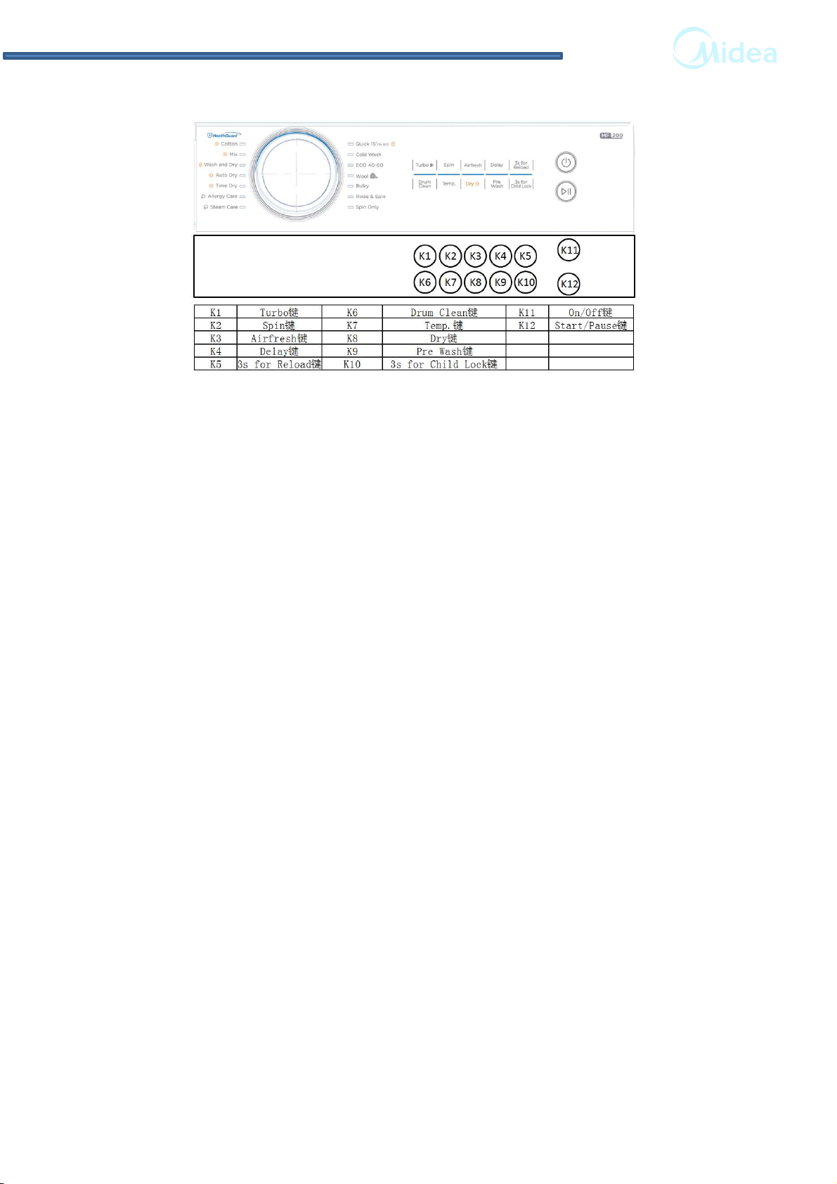
1) Press [K8] button to illuminate the whole LED display.
2) Press [K1] button, the whole LED display flashes.
3) Press [K8] to stop flash, LED display “t04”
3.2.5 Drain pump checking (t05)
1) Enter into service mode, LED displays “pup”.
2) Press [K8] button to drain out all the remaining water. If all water drained out, LED
displays “god”,and 6 minutes later ,if there is still water remains in it, LED displays
“FP”.
3) Press [K8] button to exit, LED displays “t05”
2.1.5 Pressure switch checking (t06)
1) Enter into service mode, drain out the water, LED displays LL.
2) Press [K8] button to activate inlet valve. LED displays level frequency once water
lever get the main wash level,after the water level reaching the overflow line, drain out
all the water.
2.1.6 Water temperature sensor and heater checking (t07)
1) Press [K8] button to activate the main inlet valve and get the water lever to heating
level then turn on the heater and 5 min later turned off automatically.
2) After heater turned on, LED displays the current temperature. Detect the real
temperature of inner drum and check with the numbers on the display.
3) Press [K8] button to exit, LED displays “t07”
2.1.7 Inlet valve checking (t08)
1) Enter into service mode, drain out the water, LED displays “UU”. Press [K8] button,
LED displays “out”.
2) Press [K1] button, LED displays “u2” and switch on prewash valve for 5s.
3) Press [K1] button, LED displays “u1” and switch on the main wash inlet valve
for5s.
4) Press [K1] button to switch on main wash and prewash valve and get the water
lever to setting level, then drain out the water.
2.1.8 Rotating checking (t09)
1) Enter into service mode, LED displays “tUB”
2) Press [K8] button, inner drum rotates in 45r/m clockwise for 10s and stop for 10s,
over and over again.
3) Press [K8] button to turn off the motor and exit, LED displays “t09”.
2.1.9 Spin speed checking (t10)
1) Press [K8] to enter into service mode, LED displays “spn”.
2) Press [K8] button again, the number on the display goes up in the same pace with
the real speed and when it reach 400rpm, you need to press [K1] button to get the
machine to reach its target speed.
( if declared speed ≥1000rpm, target speed is 1000rpm and if declared speed <
1000rpm,target speed is its declared speed)
3) Press [K8] button to exit and LED displays “t10”.
2 FACTORY PATTEN DETECTION

10
2.2 Self-check
Push the buttons of function and pre-washing without loosening, in the meantime
screw the program knob to the position of cotton and keep 3s, then the program will
be in the state of self test. When the buzzer toots, all the indicating lights glitter 3
times ( pushing 0.5s, the 0.5s light is on and off), then the lights are on all the time.
When the knob screw to the following position in this time and push the button of
start/off, the test is effective.
1. Delay washing test (cotton normal water):the maximum inlet water time is 10s.
2. Main washing test(cotton 40℃): the maximum inlet water time is 10s.
3. Washing test(cotton 60℃): the maximum inlet water time is 10s.
4.Heating test(cotton 90℃): estimate whether the water level is 1, if not, adding
water to 1, then begin to heat in the maximum of 10 minutes.
5.Tub leaking test(speedy washing 30℃): estimate whether the water level is 1, if not,
adding water to 1, according to cycle of clockwise 10s-stop 2s-anticlockwise 10s to
test in the rotate speed of 250rpm (fault alarm E6/E7).
6. Drain test (single drain): if the water level is below 1, it is plus 40s (malfunction
alarm E3).
7. Dehydration (single dehydration): judge whether the water level is below 1, if not,
drain water until it is below the 1 plus 20s, then dehydrate in the maximum of
speed (unbalanced test is needless), the maximum time is 10 minutes(fault alarm E5).
NOTE:
1) The tests foregoing are reversible.
2) It is need to close the door lock before each test , or else the door clock is
malfunction alarm E1.
3) The knob can be screwed to every position, the corresponding test is valid once
pushing the start/pause button.
4) If the knob is not in the position of that test, there is not responsive.
Exit need to close the power.
2.3 Marketing-show (no-water testing)
Target: in order to display the washer’s operation in the supermarket, set up
display mode.
Operation program: push the function + pre-washing button and screw the knob
to 40℃, keeping 3 minutes, when the buzzer toot, it enter the sales display mode. In
the mode, the washer without and the heater without power, run the two minutes
standard cotton washing + washing program and three minutes dehydration program
after pushing the start/pause button, then stop, if you push the start/pause button
again, the operation repeat.
Exit need to cut off the power.
2 FACTORY PATTEN DETECTION

3. UNPACKING WAYS OF MAIN PARTS
1. Undo the back cover
2. Undo top cover
3. Undo the control panel
4. Undo the lower panel
5. Undo the door lock
6. Undo the front plate
7. Undo the facade counterweight
8. Undo the gasket
9. Undo the PCB panel
10. Undo the detergent box
11. Undo the inlet valve
12. Undo the pressure
13. Undo the pulley
14. Undo the absorber pin
15. Undo the filter
16. Undo the drain pump
17. Undo the heater
18. Undo the NTC
19. Undo the door glass
20. Undo the panel support
21. Undo the drum tub assembly
22. Undo the absorber
23. Undo the motor
3 UNPACKING WAYS OF MAIN PARTS
11

121212
Operation Picture
1. Undo the rear cover
I. Undo the 4 screws
between the rear plate
and the cabinet, and then
pull it out.
2. Undo the top cover
I. Undo 2 screws fit back
Cabinet.
II. Push back the top cover
15mm until it leaves away
from the control panel,
and then take it down.
3. Undo the control panel
I. Remove the top cover
plate.
II. Draw out the detergent
drawer.
III. Loosen 2 screws on the
control panel.
IV. Loosen 2 screws on the
control panel.
V. Tilt the control panel and
take it out.
3 UNPACKING WAYS OF MAIN PARTS

131313
4. Undo the PCB
I. Remove the control panel
assembly.
II. Remove screws between
the control panel and the
PCB housing.
III. take out the PCB.
5. Undo the service plate
box
I. Open the filter cover,
release the screw on the
lower panel.
II. Turn the washing.
machine back at an angle,
pinch the clasp ,and push
it out.
6. Undo the door lock
I. Open the door of the
washing machine.
II. Pull open the door gasket.
III. Remove 2 screws on the
door lock.
IV. Take out the door lock
and draw out the plug.
7. Undo the front panel
I. Remove the top cover
plate and the control
panel.
II. Remove the screw on the
service plate box.
III. Undo 5 screws on the
front panel.
IV. Remove the outer gasket
clamp between the door
gasket and the front plate.
V. Take off the front plate.
1
2
3 UNPACKING WAYS OF MAIN PARTS

1414
8. Undo the lower
counterweight
I. Remove the front panel.
II. Remove 4 screws and pull
out the lower
counterweight.
9. Undo the inlet valve
I. Remove the top cover
plate.
II. Unplug connector and
undo 2 screws between
cabinet and inlet valve.
III. Release the clamp fixing
the inlet valve and the
inlet hose, and then pull
out the inlet hose.
10. Undo the detergent box
I. Remove the control panel.
II. Release the hose clamp
and pull out the inlet
hose.
III. Release the hose clamp
and pull out the
detergent box hose, and
then take out the
detergent box.
11. Undo the water level
sensor
I. Remove the top cover
plate.
II. Pull out the plug on the
water level sensor.
III. Loosen the water level
sensor hose clamp and
pull out the hose from
the water level sensor.
IV. Rotate the water level
sensor anticlockwise by
90º, and then pull out the
water level sensor.
3 UNPACKING WAYS OF MAIN PARTS

1515
12. Undo the gasket
I. Undo the top cover, control
panel, door lock, front
panel.
II. Undo 2 screws on clip
spring.
III. Loosen the inner gasket
clamp between the door
seal and the front of the
outer tub.
IV. Put the head of tunnel
assemble up, then take off
the gasket.
13. Undo the top bracket
I. Remove the control panel.
II. Remove 4 screws fixing the
top bracket, and then
remove it.
14. Undo the pulley
I. Undo the back cover.
II. Rotate the pulley and at
the same time pull out the
belt.
III. Remove the screw on the
pulley and then take down
the pulley.
15.Undo the fan motor
I. Undo 8 screws on the fan
flange assembly and then
take it down.
3 UNPACKING WAYS OF MAIN PARTS

161616
16. Undo the filter of drain
I.Open the lint filter door.
II.Rotate the filter knob
anticlockwise, and then pull out
the filter.
17. Undo the drain pump
I.Undo the front panel.
II.Remove 4 screws, unplug
connector, nip out the clamp
between the drain hose and
the drain pump, and then pull
out the drain hose.
18. Undo the heater
I.Remove the rear cover.
II.Remove the bolt and pull out
the heater plug.
19. Undo the NTC
I.Undo the heater.
II.Undo the NTC with special
tools.
3 UNPACKING WAYS OF MAIN PARTS

171717
20. Undo the absorber pin
I.Undo the front panel.
II.Use pliers to pinch the
absorber pin’s protuberance,
and knock the absorber pin out
from back lightly; in the same
way, remove the other two.
21. Undo the tub assemble
I.Undo the rear cover, top cover,
control panel, front panel, top
bracket, lower counterweight,
detergent box, the absorber pin,
water level sensor.
II.Undo all connection between
tub assemble and cabinet
assemble.
III.Push the rest down to front
slowly and carefully.
IV.Take off the cabinet from the
tub assemble carefully.
2 2 . U n d o t h e t u n n e l
assembly
I. Undo the tub assemble.
II. Remove 2 screws on the
clip spring.
III. Undo 5 screws on tunnel
cover.
IV. Undo 6 screws on the
condenser.
V. Undo the clamp and then
take the tunnel assemble
down.
3 UNPACKING WAYS OF MAIN PARTS

181818
23. Undo the upper
counterweight
I. Undo the tub assemble
II. Remove two screws fit on
the upper counterweight
and then pull out the upper
counterweight.
24. Undo the motor
I. Let the machine lie down on
the back and then pullout
the motor wire and
grounding wire.
II. Use spanner to remove the
motor screws, and lift up
the motor with the other
hand in case of falling to the
drain pump
25. Undo the rear tub
assembly
I. Remove the motor
II. Pull out the heater.
III. Remove the belt.
IV. Remove the screws fixing
the pulley, and then take
out the pulley.
V. Remove the screws fixing
the front and rear tub, and
then remove the tub.
VI. Remove the inner drum kit.
3 UNPACKING WAYS OF MAIN PARTS

191919
26. Undo the absorbers
I. Lift out the outer tub kit.
II. Undo the absorbers pin
between absorber and
rear tub, remove the
absorbers.
27. Undo the door glass
I. Open the door, remove 2
screws fixing the hinge
and the front panel, and
then remove the door.
II. Remove 11 screws on the
inner door.
III. Undo the outer door and
the inner door with
special tool.
3 UNPACKING WAYS OF MAIN PARTS

20
4 MALFUNCTION CODES AND EXPLANATIONS
Schedule of failure alarm
Malfunction
code Reason Possible cause Solution
E10
In 3 minutes,
the water level
doesn’t
change with
valves open
The water level
doesn’t changed in 3
minutes during filling
the water.
If the washer fills very slowly, the
water pressure from the house
might be too low. If the water inlet
valve isn't leaking and there are
no other symptoms this problem
does not need to be corrected.
Water inlet hose
Make sure that water faucet is
turned on and that the screens on
the hoses are not restricted.
Water inlet
valve
(The voltage on
the water inlet
valve is normal)
If the water pressure is good, try
cleaning the screens inside the
water inlet valve hose connection
ports. If those are clean replace
the water inlet valve.
Water level
sensor or
control switch
(No voltage on
the water inlet
valve)
A water lever control switch
controls how much water enters
the washing machine by PCB. If
the water level control switch is
defective, or more commonly, if
the small air pipe attached to the
air bell restricted, The switch will
not be able to close the electrical
contacts to the washer fill valve.
CHECK THE AIR PIPE
CHECK THE WATER LEVERL
SENSOR
CHECK THE PCB and the inner
wire between PCB and the sensor
E12
The water
level in drum
exceed a
certain level
for alarm
Restart Sometimes just restart the unit
can solve the problem.
Water inlet valve
(The voltage on the
water inlet valve is
normal)
If the washer is overflowing, the
water inlet valve has failed.
Replace it.
Water level
sensor or
control switch
(No voltage on
the water inlet
valve)
A water lever control switch
controls how much water enters
the washing machine by PCB. If
the water level control switch is
defective, or more commonly, if
the small air pipe attached to the
air bell restricted, The switch will
not be able to close the electrical
contacts to the washer fill valve.
CHECK THE AIR PIPE
CHECK THE WATER LEVERL
SENSOR
CHECK THE PCB and the inner
wire between PCB and the sensor
This manual suits for next models
1
Table of contents
Other Midea Washer manuals

Midea
Midea X8 User manual

Midea
Midea MLV45N1B Series Manual

Midea
Midea MTWM80 User manual

Midea
Midea MF200W80WB Series User manual

Midea
Midea MF200W90WB Series User manual

Midea
Midea MA100W75 User manual

Midea
Midea DMWM55 User manual

Midea
Midea Sicily Glory G01 User manual

Midea
Midea MT725B User manual

Midea
Midea KL15TTGIW User manual

Midea
Midea MFW-V1100DDi User manual

Midea
Midea MLH52N5AWW Manual

Midea
Midea MF710W User manual

Midea
Midea MFW-EC950 User manual

Midea
Midea FP-90LTL085GETM-N1 User manual

Midea
Midea MF20EW70WB User manual

Midea
Midea MFW-752S User manual

Midea
Midea Sicily Glory G01 User manual

Midea
Midea MLV47R5BWW Manual

Midea
Midea LUNAR 01 User manual