Midian VAE-80 User manual

1
VAE-80
8 Input Voice Alarm Encoder
Manual Revision: 2014-11-13
Covers Firmware Revisions:
PARTI-1: V 1.00
Covers Hardware Revisions:
PARTI-1: Rev F

2
HARDWARE SPECIFICATIONS
Voltage/Current:
ExternalPower 13-18VDC
Standby Current 138 mA
Radio Inputs/Outputs:
Audio Input Impedance ~ 2.7k
Audio Input Level 500 mvpp – 5 vpp
AGCDynamicRange 30 db
Audio Output Level Adjustable from 140 mvpp to 3 Vpp unloaded
Audio Output Impedance 1 K or 47 K Jumper Selectable
PTT Out: Open-Collector – Logic Low
Mechanical:
Dimensions: 1.45" H x 6.1” W x 7.0" L
Operating Temp: -30° to +60° C
INSTALLATION OVERVIEW
1. Test the radio and PA system for functionality.
2. Program the unit per the Product Programming Section of this manual.
3. Connect the unit into the radio and PA system per the Hardware Connection Section of this manual.
4. Program the radio per the Radio Programming Section of this manual.
*** Midian is not responsible for any damage/loss resulting from the use of Midian’s products.
GENERAL INFORMATION
The VAE-80 is a voice alarm encoder capable of playing back 8 different 20 second user pre-recorded messages
over a radio channel. Each of these 8 messages is controlled by 8 individual logic low inputs (relay contacts) from
an alarm panel. The 8 alarm messages can also be activated by DTMF sent from a radio equipped with a Touch
Tone keypad or optionally from a cellular or land line phone. Another optional feature allows the 8 messages to be
simultaneously played back over a PA system or a 600 ohm line.
The VAE-80 is two Midian products, the PARTI-1 and the AE-1 combined to make a single product. The PARTI-1
interface is used to program the functionality of the VAE-80. The AE-1 module inside the VAE-80 will never need
to be programmed.
PRODUCT PROGRAMMING
Midian’s VAE-80 is programmed via Midian’s KL-4F programmer, KL-4F-PC1 programming cable and our free
MPS software. Please reference the KL-4F manual for setup instructions of the programming software
and hardware. From the product selection screen in the software, select the PARTI-1 from the list and click
OK.
Set the parameters of the software to fit the application. If any clarifications on a feature are required, move the
mouse cursor over the feature name until the question mark appears and right click, a definition of the feature will
be shown.

3
After entering the parameters, save the file by going to File - Save As. Enter the file name in the File Name block
and click Save. Saving the file will allow for quick and easy reprogramming of units.
Push the power button on the KL-4F and within 15 seconds select Program Unit or Read Unit in the
software.
After programming or reading the unit, turn off the unit for 3 seconds and then turn back on.
Regarding the headphone/programming jack on the front of the unit:
The headphone jack on the front of the unit is used for programming.
Programming must begin within 15 seconds of turning the unit on.
Power must be cycled (power turned off and then on) after programming.
If headphones are used, they will not be active for the first 15 seconds after turning the unit on.
General Info -> Unit Information
This information area is updated when a unit is read or programmed. It will also be updated when a data file is
loaded from a previous unit read and then saved. Below is a summary of the fields:
Product - Shows a more detailed description of the product model within the series.
uP #1 Firmware Version - Indicates the reported Firmware Version of the primary microprocessor of this product.
uP #1 Loader Version - Indicates the reported Loader Version of the primary microprocessor of this product.

4
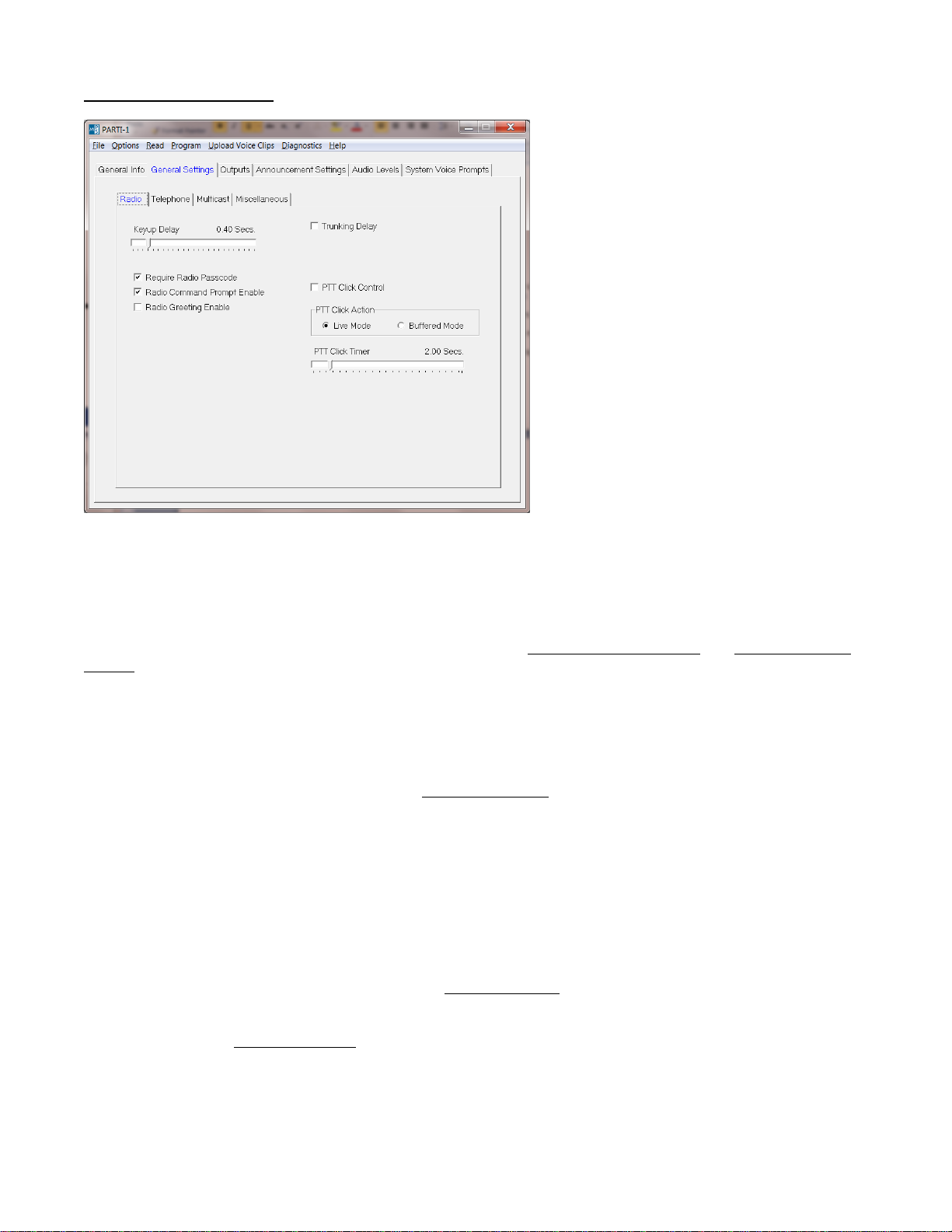
General Settings -> Radio
Keyup Delay - The system will wait this amount of time after asserting the PTT output before transmitting a voice
prompt or announcement over the radio. The amount of time needed will depend on the radio system. If CTCSS
or DCS is being used, this delay should account for the time needed to decode such signals.
Require Radio Passcode - If enabled, a passcode must be entered in order to log into the system via radio. It is
assumed that if the passcode requirement is disabled that some other method is in place to secure the system
such as a dedicated channel or CTCSS code. Note: If disabled, Radio Greeting Message and Radio Command
Prompt will also be disabled.
Radio Command Prompt Enable - If enabled, 'Enter Command' will be heard after entering the correct
passcode and releasing PTT. This may be preceded by the greeting message (if enabled). If the command
prompt and the greeting message are both disabled, PTT should not be released after entering the passcode.
Instead, proceed to enter a command.
Radio Greeting Enable - If enabled, the custom Greeting Message will be heard after entering the correct
passcode and releasing PTT. This will be followed by the command prompt (if enabled).
Trunking Delay - In trunked radio systems like LTR, it is necessary to wait for a channel to be acquired before
the system can transmit a voice prompt or announcement. Checking this box causes the system to wait for a
signal from the radio indicating that it has acquired a channel. This function requires that the LTR Delay input be
connected a point in the radio that changes state when a channel is acquired. If the signal does not indicate that
a channel has been acquired within 5 seconds of keyup, the transmission will be abandoned.
PTT Click Control - Enabling this feature allows limited access to the system using radios not equipped with
DTMF signaling. By clicking the PTT button on the radio 4 times in rapid succession, the system will enter either
Live Mode or Buffered Mode depending upon which PTT Click Action is selected. After the 4th PTT press-and-
release, the 'Speak' prompt will be heard. The user must then re-key and speak the announcement.
PTT Click Action - If PTT Click Control is enabled, this specifies the action the system will take when the proper
number of PTT clicks is detected. Select either live mode or buffered mode as the PTT Click Action.
PTT Click Timer - This specifies the maximum amount of time allowed between each PTT press-and-release for
it to be counted as a click.

5
General Settings -> Telephone
Number of Rings - Specifies the number of rings before the system answers a telephone call. If for example 2
rings are specified, the system will answer at the beginning of the 2nd ring.
Answer Delay Time - After answering a telephone call, the system will wait this amount of time before playing the
'Enter Command' prompt (or Greeting Message).
Require Telephone Passcode - If enabled, a passcode must be entered in order to log into the system via
telephone. It is assumed that if the passcode requirement is disabled that some other method is in place to
secure the system such as an unlisted telephone number.
Telephone Greeting Enable - If checked, a Greeting Message will be played when the system answers a
telephone call. This message is customizable via the Custom Audio screen under System Voice Prompts.

6
General Settings -> Multicast
Impolite Multicast - Enabling impolite multicast tells the system it is allowed to keyup even if the radio channel is
busy. When it is time to broadcast an announcement and the radio channel is busy, the system will first wait for
the Multicast Busy Lockout Delay time to expire. This will happen even if impolite multicast is disabled.
If the radio channel is still busy after that time, the system will check to see if impolite multicast is enabled. If it is,
the transmission will take place. If it is not, the transmission will be abandoned and never take place. Note that
the announcement will be broadcast over the PA system in either case.
Multicast Busy Lockout Delay - When it is time to broadcast an announcement over the radio, the radio channel
may be busy. This parameter specifies how long the system will wait for the radio channel to become unbusy
before transmitting the announcement. If the channel becomes unbusy before this time expires, the
announcement is transmitted.
If the radio channel is still busy after this time, the system will check to see if Impolite Multicast is enabled. If it is,
the transmission will take place. If it is not, the transmission will be abandoned and never take place. Note that
the announcement will be broadcast over the PA system in either case. This parameter should never be set to 0
unless Impolite Multicast is enabled. In either case it is recommended this be no less than 2 seconds.
Mutlicast Sync Window Delay - The purpose of this setting is to ensure that the announcement broadcast over
the PA is synchronized with the announcement transmitted over the radio. Synchronization is desirable when
staff members with radios are within earshot of the PA system. If synchronization is not desired, this time may be
set to 0. If there is no synchronization, broadcast over the PA and transmission over radio will start at different
times. This could make the announcement difficult to understand for those staff members with radios.
This parameter specifies how long the system will wait for the transmission over radio to begin before
broadcasting the announcement over the PA. This amount of time needs to take into account channel acquisition
time if in a trunking system as well as the programmed Keyup Delay. Also, when it is time to broadcast an
announcement over the radio, the radio channel may be busy. If that is the case, a few seconds of busy time
should be accounted for as well.

7
As soon as transmission over radio can begin, the announcement will be broadcast over the PA and transmitted
over the radio at exactly the same time. If the Multicast Sync Window Delay time expires, the announcement will
be broadcast over the PA even if transmission over the radio cannot begin. In that case, transmission over radio
may begin at a later time or not at all depending upon the Impolite Multicast and Multicast Busy Lockout Delay
settings.
General Settings -> Miscellaneous
Admin Inactivity Timeout - Administrator Mode will be terminated if there has been no administrator activity for
this amount of time. 'Goodbye' will be heard from the administrator microphone if this occurs.
DTMF Inactivity Timeout - This specifies how long the system will wait for a DTMF command to be entered. If
this time expires while the system is waiting for a command, 'Goodbye' will be heard and the user will be logged-
off the system. This applies to both radio and telephone operation.
Live Mode Timeout - This specifies how long the system will remain in Live Mode. If the user has not terminated
Live Mode by either releasing PTT or pressing '#' before this time expires, 'Goodbye' will be heard and the user
will be logged-off the system. This applies to both radio and telephone operation.
Passcode - This is the passcode that must be entered in order to log in to the system (if the passcode
requirement is enabled). It may consist of digits '0' - '9' and be 0 to 8 digits long. When a user enters a passcode
via either radio or telephone, it must be followed by '*'. When the passcode is 0 digits long, then '*' by itself is the
passcode.

8
Outputs
PTT 1 Out - Specify the polarity which will cause the radio connected to the system to keyup. For most radios
this is Low.
Announcement Settings
Pre-recorded Message 1-8 - This is the message that will be broadcast for this announcement. To upload a pre-
recorded message to the system, click on Select Wavefile and select the WAV file containing the message. The
pre-recorded message may be up to 20 seconds in length.

9
Select Wavefile - Select the .WAV file containing the pre-recorded message or voice prompt to be uploaded to
the system. Click on Upload Voice Clips on the menu bar to initiate the upload. The file format must be
Windows PCM, 8000 Hz, 8-bit mono. If the recording is not in this format, it must be converted to this format
using a third-party software tool.
Clear Wavefile Selection - Click on this to prevent the pre-recorded message or voice prompt stored in the
system from being overwritten by the selected WAV file.
Enable Multicast - If checked, the announcement will be transmitted over the radio in addition to being broadcast
over the PA system. See General Settings -> Multicast for more settings and information regarding the Multicast
feature.
Enable Alert Tone - If checked, an alert tone will be sounded before the announcement is broadcast. The alert
tone may be customized. See Alert Tone under System Voice Prompts -> Custom Audio.
Number of Repeats - This specifies the number of times the announcement will be broadcast.
Repeat Interval - This specifies the amount of time between broadcasts of the announcement if the Number of
Repeats is greater than 1.
Audio Levels
Radio Out - This controls the audio level of the Mic Audio output to the radio. It is expressed as a percentage of
the maximum recommended output level. Setting this higher than 100% may result in distortion. This should be
adjusted until voice prompts and announcements are transmitted over the radio at the proper modulation level.
PA Out - This controls the audio level of the output to the PA. It is expressed as a percentage of maximum
recommended output level. Setting this higher than 114% may result in distortion. This should be adjusted until
the announcements broadcast over the PA are at the proper volume level.

10
System Voice Prompts -> Custom Audio
Greeting Message - This is the message that will be heard if either Radio Greeting or Telephone Greeting are
enabled. To replace the default greeting with a custom greeting, click on Select Wavefile and select the WAV file
containing the greeting. The custom greeting may be up to 6 seconds in length.
Alert Tone - This is the audio clip that will be heard if the announcement setting Enable Alert Tone is checked.
To replace the default alert tone with a custom alert tone, click on Select Wavefile and select the WAV file
containing the alert tone. The custom alert tone may be up to 2 seconds in length.
System Voice Prompts -> Vocabulary

11
Message Prompt - The default system voice prompts may be replaced with custom voice prompts if desired.
This not only allows a different voice to be used, it also allows prompts to be in any language. Voice prompts
consist of the following words and phrases. Words may be up to 1 second in length and phrases may be 2
seconds. There must be a separate WAV file for each word and phrase.
Words: zero, one, two, three, four, five, six, seven, eight, nine, goodbye, okay, message, speak.
Phrases: Enter Passcode, Enter Command.
HARDWARE CONNECTION
Be certain to follow standard anti-static procedures when handling any of Midian’s products.
WALL POWER ADAPTER INPUT J1
Connect the optional wall power adapter to this input. This is not needed if powering the system from the radio
power supply via J3.
VAE-80 alarm inputs J2
Blue = Alarm 1
Yellow = Alarm 2
Violet = Alarm 3
Gray = Alarm 4
Brown = Alarm 5
Orange = Alarm 6
Red = Alarm 7
Green = Alarm 8
RADIO CONNECTOR J3
J3-1: Alarm Input (Brown): Applying a ground (logic-low) to this input triggers the alarm function. Triggering the
alarm function causes the immediate broadcast of pre-recorded message #8. If the alarm function is not desired,
this input may be left unconnected.
J3-2: External Enable (Blue): Not used. Leave unconnected,
J3-3: Mic audio (White): This is the audio output from the system to the radio transmitter. Connect to the MIC-
High or external microphone input of the base station radio.
J3-4: Ground (Black): Connect to ground of the base station radio.
J3-5: COR/COS Input (Red): This signal from the radio to the system is used by the system to determine when
to listen for commands from the radio. It is also used by the system to determine if the radio channel is busy so
that it will not transmit on a busy channel.
Connect to a point in the radio that changes logic level when carrier (CSQ), CTCSS, DCS, or talk-group is
detected. If CTCSS or DCS is being used, connection to a point that changes logic level when CTCSS or DCS is
detected is preferable over a point that changes logic level in response to carrier alone. This allows a special
CTCSS or DCS code to be dedicated to the system. In trunking radios, a talk-group detect output is preferred
over carrier alone which may give a false busy indication.
The default polarity for this input to the system is active-high. This means that the system will consider the radio
channel to be active (busy) when the logic level is high. The polarity may be changed to active-low by moving
jumper JP21 from the 1-2 position to the 2-3 position.
J3-6: External Power (Green): Connect to a 13-18 VDC source in the base station radio. If power cannot be
connected to the radio use the optional wall adapter.

12
J3-7: PTT Output (Yellow): This output from the system provides a ground (logic-low) when the system needs to
transmit over the radio. This output is an open-collector type which means that the output is an open circuit when
not transmitting. Connect this to the PTT input of the base station radio.
J3-8: Speaker – (Violet): Connect to Speaker– of the base station radio. See below for more information.
J3-9: Speaker + or Single Ended Speaker High (Orange): Audio received by the radio is fed into the system
using the Speaker +/- inputs of the system. These inputs to the system may be connected to the Speaker +/-
radio outputs. If the radio does not offer a speaker– output or if you wish to use a different RX audio output from
the radio other than speaker, connect that output to Speaker+ and leave Speaker– unconnected.
J3-10: LTR Delay (Gray): This signal from the radio to the system is used by the system to know when a channel
is acquired on a trunking system like LTR. If the radio system is not a trunked system, the input may be left
unconnected.
If on a trunking system, connect this to a point in the base station radio that changes logic level when a channel is
acquired on the trunking system. Some radio manufacturers refer to this as the Clear to Send output. Also, the
Trunking Delay option must be checked in the MPS software when configuring the system in order to support
trunking.
The default polarity for this input to the system is active-high. This means that the system will consider the radio
channel to have been acquired when the logic level is high. The polarity may be changed to active-low by moving
jumper JP20 from the 1-2 position to the 2-3 position.
SPEAKER-MICROPHONE J4
Connect the optional administrator speaker-microphone to this connector.
TELEPHONE LINE J6
If the system has the optional telephone interface installed, connect to system to the telephone line via this
connector. Be careful to connect the telephone line only to J6 and not to one of the other larger connectors or
damage may result.
PA EQUIPMENT J7
J7-1: E Lead (Brown): Not used. Leave unconnected.
J7-2: Ground (Blue): Connect to a grounding point on the PA equipment.
J7-3: PTT OC (White): Not used. Leave unconnected.
J7-4: PA TX Out A (Black): This is one side of the balanced audio output from the system to the PA microphone
input. Connect this to one side of the balanced microphone input of the PA equipment.
J7-5: Unbalanced Out (Red): This is an unbalanced audio output from the system to the PA equipment which
may be used if a balanced input is not available. The default output impedance is 1 K Ohm. If needed, remove
jumper JP9 to change output impedance to 47 K Ohm.
J7-6: Ground (Green): This supplemental ground connection is provided for use with the unbalanced audio
output if needed.
J7-7: PA TX Out B (Yellow): This is one side of the balanced audio output from the system to the PA
microphone input. Connect this to one side of the balanced microphone input of the PA equipment.
J7-8: All Call (Violet): This may be connected to the all call input of the PA equipment if needed. It is the
normally open (NO) contact of the form C relay that is energized when the system broadcasts over the PA.

13
J7-9: Wiper (Orange): This may be connected to the all call input of the PA equipment if needed. It is the wiper
of the form C relay that is energized when the system broadcasts over the PA.
AE-1 to PART-1 main board connections: This is done at the factory and should not be touched or changed.
P1:1 green of AE-1 to pin 1 of JP-5 in PARTI (RX in 1)
P1:2 red of AE-1 to P1:2 of PARTI-1
P1:4 black of AE-1 to P1:4 of PARTI-1
P1:9 white of AE-1 to P1:3 of PARTI-1
P1:11 gray of AE-1 to P1:11 of PARTI-1
P1:12 orange/white pf AE-1 to P1: 12 of PARTI-1
P1:13 violet of AE-1 to pad for anode of D-32
P2:2 red to pin 2 of JP-23 of PARTI-1 (COR 2)
P2:3 brown of AE-1 to pad of R105 going to J2:9
P2:4 black of AE-1 to pad of RJ-26 going to J2:1
P2:5 blue of AE-1 to via going to J2:10
P2:7 yellow of AE-1 to pad for R-105 going to J2:8
P2:8 green/white of AE-1 to pad for R-106 going to J2:7
P2:9 white of AE-1 to pad for RJ-23 going to J2:2
Balanced PA output adjustment:
The PARTI-1 is shipped with RP-1 in its center position.
With RP-1 in its center position adjust the PA out in the MPS software, 100% will give approximately 160mVpp at
pins 4 and 7 of J7 with a 600ohm load and .06% will give approximately 12mVpp at pins 4 and 7 of J7 with a
600ohm load. Levels above 114% in SW will cause distortion.
If the PA requires more or less then the above levels, adjustment of RP-1 will be necessary.
Adjusting RP-1 clockwise will increase the level and counterclockwise will decrease the level.
Unbalanced or single ended output adjustment:
Adjust the PA out in the MPS software to match the input of the PA system .06% will give approximately 50mVpp
pin 5 of J7 and 114% will give approximately 1 Vpp at pin 5 of J7 with a 47K load. Levels above 114% in SW will
cause distortion.
Radio output level adjustment:
Start with the impedance jumper JP11 in its default position of in and adjust the radio out level in the MPS
software to obtain full deviation of the transmitter, if the level cannot be set low enough in SW then change the
position of jumper J11 to out and then readjust the level in SW.

14
Jumper Settings:
Jumper Default Description
JP1 Out Not used.
JP3 1-2 Administrator Mic Hi.
JP4 2-3 POTS option RX.
JP5 Out Not used.
JP6 Out Not used.
JP7 1-2 PA relay enable.
JP8 Out Not used.
JP9 In Single-ended PA MIC AUDIO output impedance (In = 1 K Ohm, Out = 47 K Ohm).
JP10 3-4 Administrator PTT input.
JP11 In Radio MIC AUDIO output impedance (In = 1 K Ohm, Out = 47 K Ohm)
JP12 3-4 Administrator speaker audio.
JP13 3-4 POTS option TX.
JP14 In Normally closed relay contact to PA TX OUT B.
JP15 In Normally closed relay contact to PA TX OUT A
JP16 2-3 PA audio to transformer driver.
JP20 1-2 LTR DELAY (channel acquired) polarity (1-2 = active high, 2-3 = active low).
JP21 1-2 COR/COS (channel busy) polarity (1-2 = active high, 2-3 = active low).
JP22 Out Not used.
JP23 Out Not used.
HARDWARE ALIGNMENT
Radio Out:
While monitoring the transmitter with a service monitor, Adjust “Radio Out” for the lowest setting that will allow for
full or close to full deviation.
PA Out:
With PARTI-1 connected to PA, adjust “PA Out” for a level equal to the input level specified by the PA
manufacturer.
PRODUCT OPERATION
OPERATION USING J2 connection with 8 individual inputs
The VAE-80 is a voice alarm encoder capable of playing back 8 different 20 second user pre-recorded messages
over a radio channel. Each of these 8 messages is controlled by 8 individual logic low inputs (relay contacts) from
an alarm panel. When one of the 8 inputs receives a logic low signal the pre-recorded message associated with
that input will be played back over the radio channel.
The 8 alarm messages can also be activated by DTMF sent from a radio equipped with a Touch Tone keypad or
optionally from a cellular or land line phone.
OPERATION USING RADIO
Logging into the system: You must log in to issue commands to the system. To log in, keyup the radio and
enter the passcode '123' followed by the '*' key and then release PTT. If the passcode was not entered correctly,
the system will respond with: "goodbye". If the passcode was entered correctly, the system will respond with the
"enter command" prompt.
Broadcasting a pre-recorded message: To broadcast one of the eight pre-recorded messages, keyup the radio
and press the '*' key followed by the message number (1-8). If the command was accepted, the system will
respond with: "okay". You will be logged-off the system and the selected message will be broadcast over the PA
system.

15
Recording a message for immediate broadcast (buffered mode):Keyup the radio, press the '*9', and then
release PTT. The system will respond with: "speak". Press PTT and begin speaking. When done, release PTT.
The system will respond with: "okay". You will be logged-off the system and the message will be broadcast over
the PA system.
Notes: The message may be up to 20 seconds. If you speak for more than 20 seconds the system will time-out.
When this happens you will be automatically logged-off the system and the first 20 seconds of the message will
be broadcast over the PA system. If you decide you would like to restart the recording before you are finished,
you may press '*'. If you decide to cancel the record/playback sequence, you may press '0'. The system will
respond with "goodbye" and you will be logged-off.
Speaking directly over PA system (live mode):To speak over the PA system directly without recording, keyup
the radio, press '*0', and then release PTT. The system will respond with: "speak". Press PTT and begin
speaking. When you are done speaking, release PTT. The system will respond with "goodbye" and you will be
logged-off. Live mode is automatically terminated after 20 seconds.
Logging off: If you have logged-in and then decide you do not wish to issue any commands to the system, press
'#' while keyed to log off. The system will respond with "goodbye" and you will be logged-off. If you do not issue
any commands within 10 seconds of logging in, you will be logged-off automatically.
OPERATION USING TELEPHONE
Logging into the system: Start by dialing into the system. The system will answer at the beginning of the 2nd
ring. The system will answer with a greeting message followed by the "enter passcode" prompt. At this point you
will have 10 seconds to log in before the system disconnects. To log in, enter the passcode '123' followed by the
'*' key. If the passcode was not entered correctly, the system will respond with "goodbye" and disconnect from
the phone line. If the passcode was entered correctly, the system will respond with the "enter command" prompt.
Note: You may begin entering the passcode as soon as the greeting message begins playing if you wish to
speed-up the log-in process.
Broadcasting a pre-recorded message: To broadcast one of the eight pre-recorded messages, press the '*' key
followed by the message number (1-8). If the command was accepted, the system will respond with "okay". The
system will disconnect from the phone line and the selected message will be broadcast over the PA system.
Recording a message for immediate broadcast (buffered mode):Press '*9'. The system will respond with
"speak". Speak the message. When done press '#'. The system will respond with "okay". The system will then
disconnect from the phone line and the message will be broadcast over the PA system.
Notes: It is important to remember to press '#' when done speaking because that is the only way that the system
will know you are done. If you hang-up without pressing '#' the system will continue recording until the maximum
message length of 20 seconds is reached. If you fail to press '#' or speak for more than 20 seconds the system
will time-out. When this happens the system will disconnect from the phone line and the first 20 seconds of the
message will be broadcast over the PA system. If you decide you would like to restart the recording before you
are finished, you may press '*'. If you decide to cancel the record/playback sequence, you may press '0'. The
system will respond 'goodbye' and disconnect.
Speaking directly over PA system (live mode):To speak over the PA system directly without recording, press
'*0'. The system will respond with: "speak". Speak the message. When done press '#'. The system will respond
with "goodbye" and disconnect from the telephone line. Live mode is automatically terminated after 20 seconds.
Notes: It is important to remember to press '#' when done speaking because that is the only way that the system
will know you are done. If you hang-up without pressing '#' the system will continue broadcasting over the PA
until the Live Mode Timeout of 20 seconds is reached. If you fail to press '#' or speak for more than 20 seconds
the system will time-out. When this happens you will hear "goodbye" and the system will disconnect.

16
Logging off: If you have logged-in and then decide you do not wish to issue any commands to the system, press
'#' to log off. The system will respond with "goodbye" and disconnect from the phone line. If you do not issue any
commands within 10 seconds of logging in, the system will disconnect automatically.
QUICK ACCESS CONFIGURATION OVERVIEW
The following sections describe how to operate the system when it is configured for quick access. The quick
access configuration is one of many ways that the system can be configured. The goal of the quick access
configuration is to speed up the process of broadcasting an announcement as much as possible. This includes
disabling the passcode requirement. That will make the system less secure and more susceptible to pranksters
and unauthorized use. Therefore, there is a tradeoff between speed and security.
QUICK ACCESS CONFIGURATION SETTINGS
Starting with the factory default configuration, the following changes to the settings need to be made in order to
have the system operate in the manner described in the following sections.
Uncheck Require Radio Passcode.
Uncheck Radio Command Prompt Enable.
Set Number of Rings to 1.
Uncheck Require Telephone Passcode.
Uncheck Telephone Greeting Enable.
OPERATION USING RADIO
Logging into the system: There is no log in procedure in the quick access configuration.
Broadcasting a pre-recorded message: To broadcast one of the eight pre-recorded messages, keyup the radio
and press the '*' key followed by the message number (1-8) and then release PTT. If the command was
accepted, the system will respond with "okay" and the selected message will be broadcast over the PA system.
Recording a message for immediate broadcast (buffered mode):Keyup the radio, press the '*9', and then
release PTT. The system will respond with: "speak". Press PTT and begin speaking. When done, release PTT.
The system will respond with "okay" and the message will be broadcast over the PA system.
Notes: The message may be up to 20 seconds. If you speak for more than 20 seconds the system will time-out.
When this happens the first 20 seconds of the message will immediately be broadcast over the PA system.
Speaking directly over PA system (live mode):To speak over the PA system directly without recording, keyup
the radio, press '*0', and then release PTT. The system will respond with: "speak". Press PTT and begin
speaking. When you are done speaking, release PTT. The system will respond with: "goodbye". Live mode is
automatically terminated after 20 seconds
OPERATION USING TELEPHONE
Accessing the system: Start by dialing into the system. The system will answer at the beginning of the 1st ring.
The system will answer with the "enter command" prompt. At this point you will have 10 seconds to enter a
command before the system disconnects.
Broadcasting a pre-recorded message: To broadcast one of the eight pre-recorded messages, press the '*' key
followed by the message number (1-8). If the command was accepted, the system will respond with: "okay". The
system will disconnect from the phone line and the selected message will be broadcast over the PA system.
Recording a message for immediate broadcast (buffered mode):Press '*9'. The system will respond with
"speak". Speak the message. When done press '#'. The system will respond with "okay". The system will then
disconnect from the phone line and the message will be broadcast over the PA system.

17
Note: It is important to remember to press '#' when done speaking because that is the only way that the system
will know you are done. If you hang-up without pressing '#' the system will continue recording until the maximum
message length of 20 seconds is reached. If you fail to press '#' or speak for more than 20 seconds the system
will time-out. When this happens the system will disconnect from the phone line and the first 20 seconds of the
message will be broadcast over the PA system. If you decide you would like to restart the recording before you
are finished, you may press '*'. If you decide to cancel the record/playback sequence, you may press '0'. The
system will respond 'goodbye' and disconnect.
Speaking directly over PA system (live mode):To speak over the PA system directly without recording, press
'*0'. The system will respond with: "speak". Speak the message. When done press '#'. The system will respond
with "goodbye" and disconnect from the telephone line. Live mode is automatically terminated after 20 seconds.
Notes: It is important to remember to press '#' when done speaking because that is the only way that the system
will know you are done. If you hang-up without pressing '#' the system will continue broadcasting over the PA
until the Live Mode Timeout of 20 seconds is reached. If you fail to press '#' or speak for more than 20 seconds
the system will time-out. When this happens you will hear "goodbye" and the system will disconnect.
Disconnecting: If you have dialed-in and then decide you do not wish to issue any commands to the system,
press '#'. The system will respond with "goodbye" and disconnect from the phone line. If you do not issue any
commands within 10 seconds of dialing in, the system will disconnect automatically.
ADMINISTRATOR SPEAKER-MICROPHONE OPERATION
The administrator speaker-microphone is used to change or review the pre-recorded messages. The
administrator microphone is an option and must be purchased separately. Contact your sales person for more
information
Starting an administrator session: Press and hold the middle button on the speaker-microphone for
approximately 1.5 seconds until "message one" is heard.
Selecting a pre-recorded message to change: Press the middle button briefly. The word "message" will be
heard followed by a number "one" through "eight". Pressing the middle button again will advance to the next
message number.
Changing a pre-recorded message: After selecting the message number to change as described above, press
and hold the top (PTT) button. Begin speaking the new message immediately after pressing PTT. When you are
done speaking, release PTT. The system will respond "okay" after PTT is released and return to message
selection mode.
Note: The message may be up to 20 seconds. If you speak for more than 20 seconds the system will time-out.
When this happens, "okay" will be heard and the system will return to message selection mode. Only the first 20
seconds of the message will be stored.
Reviewing a pre-recorded message: Press the middle button twice quickly to hear what has been recorded for
the selected message number.
Ending an administrator session: Press and hold the middle button for approximately 1.5 seconds until
"goodbye" is heard. The administrator session will end automatically after 10 seconds of inactivity.

18
GENERAL NOTES
* The system may be accessed using a radio, telephone line, or speaker-microphone. Only one of these may be
used at any given time. If one method of access is in use when an attempt to use another is made, that other
method of access will be ignored. For example if somebody has logged into the system using a telephone line, a
radio user cannot log in at the same time. In such an instance, the radio user will receive no responses from the
system.
* If you issue a new command to the system while playback of a pre-recorded message is in progress, it will be
terminated.
* The Alarm Input has the highest priority in the system. If it is activated, any operation in progress is immediately
terminated and broadcast of pre-recorded message #8 will begin.
USER QUICK REFERENCE GUIDE
*1 Broadcast pre-recorded message #1.
*2 Broadcast pre-recorded message #2.
*3 Broadcast pre-recorded message #3.
*4 Broadcast pre-recorded message #4.
*5 Broadcast pre-recorded message #5.
*6 Broadcast pre-recorded message #6.
*7 Broadcast pre-recorded message #7.
*8 Broadcast pre-recorded message #8
*9 Record a message for immediate broadcast (buffered mode).
*0 Connect directly to the PA system (live mode).
*# Terminate broadcast in progress.
* Function depends on operation in progress:
1) Press after entering passcode to log in.
2) Press while recording to restart a recording already in progress.
# Function depends on operation in progress:
1) Press when done recording a message for instant playback.
2) Press to terminate live mode.
3) Press to log off system without entering any commands.
0) Press while a recording is in progress to cancel record/playback sequence.
ADMINISTRATOR QUICK REFERENCE GUIDE
Middle button, long press: Toggle administrator mode on/off.
Middle button, short press: Advance to next message number.
Middle button, double press: Review currently selected message.
PTT button: Press while speaking to record selected message number.

19
TECHNICAL NOTES
Radio Compatibility: Midian has taken the utmost care to ensure the unit integrates with the radio with minimal
impact to the features of the radio. However, some features may not be available in the radio when this product is
used. If a feature is not available, please contact Midian to see if the feature can be added.
***Midian Electronics Inc. is not responsible for any damage/loss resulting from the use of Midian’s products.
WARRANTY
Midian Electronics warrants its telecommunications products (tone signaling, voice scrambling, fleet
management, etc.) to be free from defects in material and workmanship for three years from date of
shipment.
MIDIAN CONTACT INFORMATION
MIDIAN ELECTRONICS, INC.
2302 East 22nd Street
Tucson, Arizona 85713 USA
Toll-Free: 1-800-MIDIANS
Main: 520-884-7981
E-mail: sales@midians.com
Web: www.midians.com

1
1
2
2
3
3
4
4
5
5
6
6
7
7
8
8
9
9
10
10
11
11
12
12
13
13
14
14
15
15
16
16
D D
C C
B B
A A
VAN
VAN
50mV - 10VPP
50dB
VAN
1.2VPP
C
DECODER_2
DECODER_1 DTMF
DECODER
IN SYSTEM
SERIAL PROGR.
3.3V
VAN
50mV - 10VPP
50dB
VAN
1.2VPP
TX_A
TX_A
LINE_IN_A
LINE_IN_B
LINE_IN_A
LINE_IN_B
M_LEAD_N/O
WIPER
N/C
TX_600_Ohm_OUT_A
TX_600_Ohm_OUT_B
PTT_OPEN_COLLECTOR
RING
HOOK
12V
EXT_MIC_HI
MIC_MUTE
VALIDATE
SPKR_MIC_TELCO_DRIVER
TAPE_RECORD/PROG OUT
DECODER_1
DECODER_2
12V
12V
COR/COS_IN_UED
COR/COS_IN_UED
E_LEAD_2
4-WIRE OPTION - RX IN
VALIDATE/ALARM INPUT
SPEAKER_ENABLE
AGC
AGC
EXT_MIC_PTT_DISPTACH
EXT_MIC_PTT_2
EXT_MIC_PTT_1
EXT_MIC_PTT_1
EXT_MIC_PTT_2
VAN
TX_B
TX_A
TX_B
SPKR_MIC_TELCO_DRIVER
TX_A
TX_B
TX_B
12V
12V
3.3V
5V
12V
DECODER_1
ENABLE_1
ENABLE_2
ENABLE_1 ENABLE_2
5V
5V
5V
5V
5V
5V
5V
5V
5V
5V
5V
5V
5V
5V
5V
5V
5V
3.3V 3.3V 3.3V
GUARD_TONE
GUARD_TONE
3.3V
3.3V
5V
RX_IN_2
5V
CHASSIS GND
J5
(MULTITURN)
SQUELCH_NOISE
SQUELCH_NOISE
12V
5V
12V
VAN VAN
VAN RX_IN_3
RX_IN_3
SPKR_OPT_2
RX_IN_2
RX_IN_2
RX_IN_3
ENABLE_1
NOTE:
J3:1 -
PR-10 : VALIDATE INPUT
VAE-10 : ALARM INPUT
IS-2 : NOT CONNECTED
POTS OPTION
OPTIONAL 4-WIRE TX LINE DRIVER/NOTCH FILTER
SPEAKER MIC OPTION
5V
0R
R33
*
C12
0R
R64
3.3K
R58
.001u
C154
.001u
C153
.068u
C150
.047u
C30
.0047u
C29 .01u
C10 .01u
C35
.0047u
C31
.047u
C34
.068u
C151
1u
C16
750K
R80
30K
R94
NOTCH FILTER REMOVES 2175Hz FROM VOICE
2175Hz
TIP
1
RING
2
XMIT(-)
9
RCV 8
VCC 10
GND
12
RI 5
OFFHK 4
XMIT(+) 11
D/V 6
PSQ
7
*
U10
SPKR_OPT_1
1M
R113 47K
R126
BSS
Q22
BSS
Q19 BSS
Q20
120K
R169
10K
R86
1M
R107
47K
R72
BSS
Q13
BSS
Q3 BSS
Q12
120K
R97
10K
R65
RX_IN_1
SB1
D24
5V
*
R122
*
R85
*
Q16
*
Q14
*
Q15
*
R129
*
R74 *
*
D9
*
R10
RED
CH_ACQ1
D1
470R
R5
470R
R4
YEL
COR_1
D6
5V
*
R112
*
R99
*
Q21
*
Q17
*
Q18
*
R153
*
R76
*
R11
*
*
D10
)
JP20:1
JP20:2
JP20:3
JP21:3
JP21:2
)
JP21:1
*
R105
100p
C92
560p
C93
1K
R141
10K
R39
200K
R44
33K
R48
1K
R59
100K
R43
200K
R60
1K
R52
2.2u
C36
47K
R51
TP19
JP22:1
JP22:2
JP23:1
*
*
D11
*
R12
100K
R135
560p
C79
JP22:3
JP23:2
JP23:3 SB1
D20
0R
R32
COR_2_HFSN
COR_2_HFSN
0R
RJ8
1K
R143
560p
C94
100p
C95
*
R108
2.2u
C106
560p
C108
100p
C109
10K
R26
200K
R40
100R
R115
E_LEAD_2
22K
R87
1.8K
R88
.012u
C133
24K
R148
RX_IN_1
RX_IN_1
OPTIONAL UED-1 2 TONE/5 TONE DECODER
-
+
2
3
1
411
LMV324
U8:1
-
+
6
5
7
LMV324
U8:2
-
+
9
10
8
LMV324
U8:3
-
+
13
12
14
LMV324
U8:4
-
+
2
3
1
411
LMV324
U5:1
-
+
9
10
8
LMV324
U5:3
-
+
6
5
7
LMV324
U5:2
-
+
13
12
14
LMV324
U5:4
NORMAL H-PASS NOISE SQUELCH FILTER
OPTIONAL BANDPASS/LO-PASS FILTER
0R
RJ18
0R
RJ23
560p
C13
2175Hz
+
_
+
_
+
_
+
_
.47u
C26
1 2
JP6
REMOVE JP6 WHEN USING
HF SQUELCH NOISE IN
2.7K
RC1
--I I--
220p
RC3
/\ \/
/\
\/
150K
RC2
--I I--
.001u
RC5
/\ \/
/\
\/
15K
RC4
/\ \/
/\
\/
82K
RC6
100p
C149
27K
R81
100p
C144
470K
R77
.1u
C52
/\
\//\\/
27K
RC8
.1u
C74
TP30
*
R54
2.2u
C75
100K
R152
*
D17
*
R45
4.7K
R55
OPTIONAL IN/OUT
PAD2
*
R66
0R
R16
2.7K
R62
*
R61
3.3K
R56
3.3K
R150
.015u
C40
.015u
C127
.0047u
C128
TP31
1K
R151
TP1 TRANSPOND
SELECT REPEAT MODE
P1:1
12V
RED P1:2
COR/COS IN UED
P1:3
GROUND
BLACK P1:4
ALERT TONE
BLUE P1:5
RX TONE IN
ORANGE P1:6
MON/SQ OUT
P1:7
MIC MUTE
P1:8
PTT OUT
P1:9
HORN/SCAN/DISABLE
GRAY/WHITE P1:10
PTT IN
P1:11
PROG IN
ORANGE/WHITE P1:12
EMERGENCY IN
P1:13
TP2
TP3
TP4
TP5
TP6
TP7
TP9
TP8
5V
100K
R123
TP11
*
RJ1
TP10
TP12
P2:5
P2:4
P2:3
P2:2
P2:1
32 KHz
Y1 12p
C39
100p
C37
*
R36 47K
R15 47K
R19
DEBUG
TP34
TP35
TP36
SB1
D16
*
D13
SB1
D15
SB1
D14
47K
R23
0R
R18 .1u
C15
*
R27 *
C25
10K
R3
2
5
1
4
3
MONITOR
RECORD
PROG
J8
100p
C1
0R
R182
47K
R47
.01u
C33
TP18
100K
R82
SB1
D19
3.3K
R46
TP17
3.3K
R41
.012u
C21
3.3K
R42
.015u
C32
.0047u
C28
.1u
C27
1K
R50
*
R156
11 33
22
*
RP2
*
R157
*
R155
*R162
.1u
C132
*
R166
-
+
13
12
14
LM660
U12:4
-
+
2
3
1
411
LM660
U12:1
-
+
9
10
8
LM660
U12:3
-
+
6
5
7
LM660
U12:2
*
R161
*
R159
*
R170
*
R164
*
R160
*
R168
.47u
C143
220K
R177
*
R175
47K
R181
10K1%
R165
10K
R178
*
R158
*
R167
*
R173
*
R163
*
R171
47KR172
.001u
C131
10K1%
R176
11 33
22
*
RP3
2.2u
C96
560p
C99
100p
C98
G
S D
5460
Q4
10K
R53
.022u
C152
100p
C97
100p
C103
4.7u
C38
12
)
IMPEDANCE
JUMPER
JP9
47K
R134
100p
C104
560p
C105
.001u
C101 100p
C100
560p
C102
0R
R136 *
R138
*
R106
TP26
.001u
C82
100p
C84
560p
C83
4001
D32
SQUELCH NOISE IN
*
J2:1
EXT ENABLE
J2:2
MIC AUDIO
J2:3
GROUND
J2:4
COR/COS
J2:5
13.6V EXT B+
J2:6
PTT OUT
J2:7
SPEAKER-
J2:8
SPEAKER+
J2:9
LTR DELAY
J2:10
J2:11
J2:12
RADIO 2
RJ45-10
100p
C22
560p
C17
TP14
2R
R28
.001u
C19
100p
C24
560p
C20
TP13
2.2u
C14
IN1
1
ENA
3
GND
2RES 4
OUT 5
MIC5206 3.3V
U4
10K
R25
10K
R24
10K
R38
*
R37
0R
R35
TP33
.001u
C6
100p
C5
560p
C7
2.2u
C8
0R
R13
IN
1
GND
2
OUT 3
LM7805
U1
.001u
C18
100p
C4
560p
C3
2.2u
C2
RED
PWR
D4
1K
R1
.001u
C140
100p
C135
560p
C136
2.2u
C137
IN
1
GND
2
OUT 3
2940A
U13
0R
R180
TP16
2
1
3
EXT PWR
J1
4001
D34
4001
D33
.001u
C85
100p
C87
560p
C86
47K
R20
100K
R30
200K
R17
4.7u
C11
1K
R22
10K
R14
2.2u
C9
33K
R29
1K
R21
TP15
100p
C112
100p
C107
.001u
C113
100p
C111
560p
C110
*
R140 *
R109
TP27
0R
R139
100p
C114
560p
C115
1 2
)
IMPEDANCE
JUMPER
JP11
47K
R103
560p
C80 100K
R137
GRN
PTT_1
D5
470R
R2
SB1
D29
100p
C116
SEE NOTE
BELOW
RADIO 1
RJ45-10
J3:1
EXT ENABLE
J3:2
MIC AUDIO
J3:3
GROUND
J3:4
COR/COS
J3:5
13.6V EXT B+
J3:6
PTT OUT
J3:7
SPEAKER-
J3:8
SPEAKER+
J3:9
LTR DELAY
J3:10
J3:11
J3:12
TP37
TP38
POTS OPTION
J6:1
YEL
J6:2
GRN
J6:3
RED
J6:4
BLK
J6:5
J6:6
J6:7J6:8
*
2KV
C126
*
2KV
C125
150R
L5
150R
L6
*
RESETTABLE FUSE
F6
*
RESETTABLE FUSE
F5
*
TZ6
*
TZ5
1u
C78
1K
R125
1KR120
1KR119
1KR121
.47uC70
.47uC69
.47uC71
.47u
C72
0R
C61
0R
R102
*
R101
.47u
C60
4.7K
R100
YEL
RING
D7
YEL
HOOK
D2
470R
R6
*
2KV
C123
*
2KV
C90
*
L1
*
L2
*
RESETTABLE FUSE
F1
*
RESETTABLE FUSE
F2
*
TZ1
*
TZ2
*
R130
*
R131
*
C76
*
R132
SB1
D28
SB1
D27
100K
R83
5V
100K
R78
1
2
34
5
6T2:1
7
8
GND
T2:2
100p
C122
100p
C119
*
R127 4.7K
R149
5.6K
R144
1u
C81
100p
C121
4001
Q11
.47u
C91
100K
R146
SB1
D31
100p
C120
100p
C118
100p
C117
.0022u
C141 200K
R124
2R
R147
4.7uC88
1uC73
.0022u
C142
2.2u
C64
200K
R111
.47uC66
.47uC67
.47uC68
.47uC65
100K
R114
IN+ 3
IN- 4
SD 1
BYP 2
VO+
5
VO-
8
GND
7
VDD 6
TH
9
TPA6203
U11
100K
R142
*
C42
.47u
C41
470K
R70
470K
R71
470K
R69
.47u
C53
470K
R84
TP20
TP28
TP29
PAD6
100K
R57
100K
R63
BSS
Q7
RED
DTMF
D8
470K
R67
SD1
D18
1.2M
R68
.1u
C46
22p
C50
22p
C51
4.7M
R79
3.58 MHz
Y2
.47u
C47
100K
R75
*
R73
OPTIONAL
PAD3
Q1 12
Q2 13
Q4 15
Q3 14
IN+ 1
GS
3
VRef 4
INH
5
ESt
18
IN-
2
PWDN
6
StD 17
OSC2 9
OSC1 8
TOE 11
VSS
10
St/GT
19
VDD 20
NC1
7
NC2
16
8870
U7
470R
R8
GREEN
RELAY
D3
4.7K
R128
B25
Q8
TP21
SD1
D30
JP7:2
)
JP7:1
JP7:3
.47u
C57
*
R154
300R
R90
1
2
3 4
5
6
T1:1
7
8
GND
T1:2
-
+
6
5
7
TLC272
U9:2
-
+
2
3
1
84
TLC272
U9:1
10K1%
R91
10K1%
R93 36K
R96
0R
R89
*
C56
.47u
C134
*
C55
11
33
22
100K
RP1
TP25
300R
R98
*
TZ3
*
TZ4 *
2KV
C124
150R
L3
*
RESETTABLE FUSE
F4
*
2KV
C89
150R
L4
*
RESETTABLE FUSE
F3
MODE IN
J4:1
J4:2
EXT MIC HI
J4:3
EXT MIC GND
J4:4
NU
J4:5
EXT MIC PWR
J4:6
PTT
J4:7
SPEAKER-
J4:8
SPEAKER+
J4:9
NU
J4:10
J4:11
J4:12
*
C77
B25
Q1
G
S D
5460
Q2
B25
Q5
B25
Q6
4001
Q9
4001
Q10
0R
RJ9
TP32
P1-3 16
P5-1 13
VDD 42
P3-1
11
P3-5
9
P4-5
4
P4-7
3
P2-6 37
P3-7
8
P2-7 47
P3-6
28
P5-2
24
P3-4 27
P1-2
20
VSS
18
P2-4_AREF
36
P0-7 43
TXITXI
P0-1
46 RXIRXI
P2-5
48
P0-3 45
P0-6 41
P4-1
6
P0-5 44
P2-3
1
P2-1
2
P0-0 38
P0-4 40
RXORXO
P0-2
39 TXOTXO
P2-0
34
P1-4
21
P1-6
22
SMP
7
P2-2 35
P1-1 17
P1-0 19
XRES 29
P3-0
25
P5-0 23
P3-2 26
P5-3 12
P3-3 10
P4-3
5
P1-5 15
P1-7 14
P4-6 33
P4-4 32
P4-0 30
P4-2 31
PAD
0
U6
CP
CJS
2010-04-26 DML
2014-04-03
F-4
1 of 1 7705
MIDIAN ELECTRONICS, INC.
DATE:
DESIGN:
DWN BY:
REV:
APPR
COPYRIGHT ©
REV
SHEET PROJECT NUMBER
DOCUMENT NAME
SCHEMATIC
2014
PUBLIC ADDRESS RADIO/TELEPHONE INTERFACE
PARTI-1
GND1 GND2 GND3
10
1
+
-
M LEAD RELAY
K1:1
3
2
4
K1:2
8
9
7
K1:3
1 2
)
JP15
1 2
)
JP14
JP8:2
JP8:1
JP8:3
PA
0R
RJ11
0R
RJ12
*
RJ4
*
RJ5
*
RJ2
*
RJ3
TP24
TP22
TP23
E LEADJ7:1
GNDJ7:2
PTT OCJ7:3
PA OUT AJ7:4
UNBAL OUTJ7:5
GNDJ7:6
PA OUT BJ7:7
ALL CALLJ7:8
WIPERJ7:9
N/CJ7:10 J7:11
J7:12
1 2
JP1
*
RJ7_21
*
RJ7_23
5V
12V
10K
R192
10K
R193
1u
C155
VAN6V
VAN6V
VAN6V
VAN6V
VAN6V
VAN6V
1u
C156
1u
C157
1 2
)
JP12
3 4
5 6
1 2
)
JP10
3 4
5 6
JP5:1
JP5:2
JP5:3
JP5:4
1 2
JP13
3 4
5 6
JP4:1
JP4:2
JP4:3
JP4:4
)
JP16:1
JP16:2
JP16:3
)
JP3:1
JP3:2
JP3:3
470R
R9
1K
R191
2
DN
3
UP
1
SW1
*
C130
*
C129
SPKR_OPT_1
SPKR_OPT_2
SPKR_MIC_TELCO_DRIVER
0R
RJ24
0R
RJ25
CS
1
SO
2
SI
5
SCK
6
VCC 8
HOLD 7
WP 3
GND 4
25VF016
U2
CS
1
SO
2
SI
5
SCK
6
VCC 8
HOLD 7
NC 3
GND 4
*
U3
*
RJ6 *
RJ7
0R
RJ10
1K
R186
SB1
D35
SB1
D36
*
D37
*
D38
SQUELCH_NOISE
*
RJ26
X1 1
X2 2
Vbackup 3
CS 4
GND
5
DIN
6
DOUT
7
SCLK
8
SQW/INT
9
VCC 10
*
U14
*
Y3
*
C158
5V
*
RJ28
*
R197
*
R199
*
R198
11
33
22
*
RP4
1.8V
*
C159
*
C160
*
R195
*
R196
1.8V
A1 2
GND
4
VCCA 1
B1
7
VCCB 8
A2 3
DIR
5
B2
6
*
U17
A1
2
GND
4
VCCA 1
B1 7
VCCB 8
A2
3
DIR
5
B2 6
*
U18
5V3.3V
5V1.8V
1A
2
GND
4
1OE
1
2OE
7
VCC 8
1B 3
2A
52B 6
*
U21
1A
2
GND
4
1OE
1
2OE
7
VCC 8
1B 3
2A
52B 6
*
U19
1A
2
GND
4
1OE
1
2OE
7
VCC 8
1B 3
2A
52B 6
*
U20
GPIO01
1
GPIO02
2
GPIO03
3
GPIO04
4
GPIO05
5
GPIO06
6
GND
7 VCC 8
BOOT
9
RESET
10
CTS 11
RTS 12
RXD 13
TXD 14
LPO
15
GPIO07
16
*
U16
5V
5V
5V
*
R202
*
R203
*
R204
*
R205
5V 5V
*
R201
5V
RTS
CTS
P1_7
P1_5
P1_7
P1_5
PROG_IN
PROG_OUT
PROG_IN
PROG_OUT
0R
R200
BT_SEL
BT_SEL
RTC_INT
*
RJ27
RTC_INT
5V
0R
RJ29
0R
RJ30
RTS
CTS
3.3V
100K
R206
PROG IN
TP45
P3:1
P3:2
P3:3
P3:4
P3:5
P3:6
P3:7
P3:8
P3:9
P3:10
*
COIN 3V
BAT1
BSS
Q24
P2
Q23
100K
R207
5V
*
R208
1K
R7
*
C161
*
R209
5V
*
C162
*
R210
5V
*
C163
*
R211
5V
*
C164
*
R212
5V
*
Q25
IN2
7
NC
4
IN1
8
OUT2 2
GND
5
OUT1 1
SD
6
FB 3
*
U15
FOR PARTI ONLY
LINE_IN_A
UNBALANCED OUT
10KR116
10KR117
10KR118
10K
R110
47K
R145
10u
C23
--I
680p
RC7
30K
R95
*
D40
*
D41
18V
D42
18V
D43
.47u
C63
.47u
C62
1K
R188
1K
R187
330R
R104
330R
R133
2.2u
C54
1K
R31
1K
R49
10K
R174
10K
R92
PIBAT101
PIBAT102
COBAT1
PIC101
PIC102
COC1
PIC201
PIC202
COC2
PIC301
PIC302
COC3
PIC401
PIC402
COC4
PIC501
PIC502
COC5
PIC601
PIC602
COC6
PIC701
PIC702
COC7
PIC801
PIC802
COC8
PIC901
PIC902
COC9
PIC1001 PIC1002
COC10
PIC1101
PIC1102
COC11
PIC1201 PIC1202
COC12
PIC1301
PIC1302
COC13
PIC1401
PIC1402
COC14
PIC1501
PIC1502
COC15
PIC1601
PIC1602
COC16
PIC1701
PIC1702
COC17
PIC1801
PIC1802
COC18
PIC1901
PIC1902
COC19
PIC2001
PIC2002
COC20
PIC2101
PIC2102
COC21
PIC2201
PIC2202
COC22
PIC2301
PIC2302
COC23
PIC2401
PIC2402
COC24
PIC2501
PIC2502
COC25
PIC2601
PIC2602
COC26
PIC2701 PIC2702
COC27
PIC2801
PIC2802
COC28
PIC2901 PIC2902
COC29
PIC3001
PIC3002
COC30
PIC3101 PIC3102
COC31
PIC3201
PIC3202
COC32
PIC3301
PIC3302
COC33
PIC3401 PIC3402
COC34
PIC3501 PIC3502
COC35
PIC3601
PIC3602
COC36
PIC3701
PIC3702
COC37
PIC3801
PIC3802
COC38
PIC3901
PIC3902
COC39
PIC4001
PIC4002
COC40
PIC4101 PIC4102
COC41
PIC4201 PIC4202
COC42
PIC4601 PIC4602
COC46
PIC4701 PIC4702
COC47
PIC5001 PIC5002
COC50
PIC5101 PIC5102
COC51
PIC5201 PIC5202
COC52
PIC5301 PIC5302
COC53
PIC5401
PIC5402
COC54
PIC5501PIC5502
COC55
PIC5601PIC5602
COC56
PIC5701
PIC5702
COC57
PIC6001PIC6002
COC60
PIC6101PIC6102
COC61
PIC6201 PIC6202
COC62
PIC6301 PIC6302
COC63
PIC6401
PIC6402
COC64
PIC6501PIC6502
COC65
PIC6601 PIC6602
COC66
PIC6701PIC6702
COC67
PIC6801PIC6802
COC68
PIC6901PIC6902
COC69
PIC7001PIC7002
COC70
PIC7101PIC7102
COC71
PIC7201
PIC7202
COC72
PIC7301 PIC7302
COC73
PIC7401PIC7402
COC74
PIC7501
PIC7502
COC75
PIC7601PIC7602
COC76
PIC7701
PIC7702
COC77
PIC7801
PIC7802
COC78
PIC7901
PIC7902
COC79
PIC8001
PIC8002
COC80
PIC8101
PIC8102
COC81
PIC8201
PIC8202
COC82
PIC8301
PIC8302
COC83
PIC8401
PIC8402
COC84
PIC8501
PIC8502
COC85
PIC8601
PIC8602
COC86
PIC8701
PIC8702
COC87
PIC8801 PIC8802
COC88
PIC8901
PIC8902
COC89
PIC9001
PIC9002
COC90
PIC9101PIC9102
COC91
PIC9201
PIC9202
COC92
PIC9301
PIC9302
COC93
PIC9401
PIC9402
COC94
PIC9501
PIC9502
COC95
PIC9601
PIC9602
COC96
PIC9701
PIC9702
COC97
PIC9801
PIC9802
COC98
PIC9901
PIC9902
COC99
PIC10001
PIC10002
COC100
PIC10101
PIC10102
COC101
PIC10201
PIC10202
COC102
PIC10301
PIC10302
COC103
PIC10401
PIC10402
COC104
PIC10501
PIC10502
COC105
PIC10601
PIC10602
COC106
PIC10701
PIC10702
COC107
PIC10801
PIC10802
COC108
PIC10901
PIC10902
COC109
PIC11001
PIC11002
COC110
PIC11101
PIC11102
COC111
PIC11201
PIC11202
COC112
PIC11301
PIC11302
COC113
PIC11401
PIC11402
COC114
PIC11501
PIC11502
COC115
PIC11601
PIC11602
COC116
PIC11701 PIC11702
COC117
PIC11801 PIC11802
COC118
PIC11901
PIC11902
COC119
PIC12001
PIC12002
COC120
PIC12101
PIC12102
COC121
PIC12201
PIC12202
COC122
PIC12301
PIC12302
COC123
PIC12401
PIC12402
COC124
PIC12501
PIC12502
COC125
PIC12601
PIC12602
COC126
PIC12701 PIC12702
COC127
PIC12801
PIC12802
COC128
PIC12901PIC12902
COC129
PIC13001PIC13002
COC130
PIC13101PIC13102
COC131
PIC13201PIC13202
COC132
PIC13301 PIC13302
COC133
PIC13401PIC13402
COC134
PIC13501
PIC13502
COC135
PIC13601
PIC13602
COC136
PIC13701
PIC13702
COC137
PIC14001
PIC14002
COC140
PIC14101PIC14102
COC141
PIC14201PIC14202
COC142
PIC14301PIC14302
COC143
PIC14401
PIC14402
COC144
PIC14901PIC14902
COC149
PIC15001
PIC15002
COC150
PIC15101
PIC15102
COC151
PIC15201
PIC15202
COC152
PIC15301
PIC15302
COC153
PIC15401
PIC15402
COC154
PIC15501
PIC15502
COC155
PIC15601PIC15602
COC156
PIC15701 PIC15702
COC157
PIC15801
PIC15802
COC158
PIC15901
PIC15902
COC159
PIC16001
PIC16002
COC160
PIC16101
PIC16102
COC161
PIC16201
PIC16202
COC162
PIC16301
PIC16302
COC163
PIC16401
PIC16402
COC164
PID101
PID102
COD1
PID201
PID202
COD2
PID301
PID302
COD3
PID401
PID402
COD4
PID501
PID502
COD5
PID601
PID602
COD6
PID701 PID702
COD7
PID801
PID802
COD8
PID901PID902
COD9
PID1001
PID1002
COD10
PID1101
PID1102
COD11
PID1301
PID1302
COD13
PID1401
PID1402
COD14
PID1501
PID1502
COD15
PID1601
PID1602
COD16
PID1701
PID1702
COD17
PID1801PID1802
COD18
PID1901
PID1902
COD19
PID2001
PID2002
COD20
PID2401
PID2402
COD24
PID2701
PID2702
COD27
PID2801
PID2802
COD28
PID2901
PID2902
COD29
PID3001
PID3002
COD30
PID3101
PID3102
COD31
PID3201PID3202
COD32
PID3301 PID3302
COD33
PID3401 PID3402
COD34
PID3501
PID3502
COD35
PID3601
PID3602
COD36
PID3701
PID3702
COD37
PID3801
PID3802
COD38
PID4001
PID4002
COD40
PID4101
PID4102
COD41
PID4201
PID4202
COD42
PID4301
PID4302
COD43
PIDEBUG01
CODEBUG
PIF101PIF102
COF1
PIF201PIF202
COF2
PIF301PIF302
COF3
PIF401PIF402
COF4
PIF501PIF502
COF5
PIF601PIF602
COF6
PIGND101
COGND1
PIGND201
COGND2
PIGND301
COGND3
PIJ101
PIJ102
PIJ103
COJ1
PIJ201
COJ2:1
PIJ202
COJ2:2
PIJ203
COJ2:3
PIJ204
COJ2:4
PIJ205
COJ2:5
PIJ206
COJ2:6
PIJ207
COJ2:7
PIJ208
COJ2:8
PIJ209
COJ2:9
PIJ2010
COJ2:10
PIJ2011
COJ2:11
PIJ2012
COJ2:12
PIJ301
COJ3:1
PIJ302
COJ3:2
PIJ303
COJ3:3
PIJ304
COJ3:4
PIJ305
COJ3:5
PIJ306
COJ3:6
PIJ307
COJ3:7
PIJ308
COJ3:8
PIJ309
COJ3:9
PIJ3010
COJ3:10
PIJ3011
COJ3:11
PIJ3012
COJ3:12
PIJ401
COJ4:1
PIJ402
COJ4:2
PIJ403
COJ4:3
PIJ404
COJ4:4
PIJ405
COJ4:5
PIJ406
COJ4:6
PIJ407
COJ4:7
PIJ408
COJ4:8
PIJ409
COJ4:9
PIJ4010
COJ4:10
PIJ4011
COJ4:11 PIJ4012
COJ4:12
PIJ501
COJ5
PIJ601
COJ6:1
PIJ602
COJ6:2
PIJ603
COJ6:3
PIJ604
COJ6:4
PIJ605
COJ6:5
PIJ606
COJ6:6
PIJ607
COJ6:7
PIJ608
COJ6:8
PIJ701
COJ7:1
PIJ702
COJ7:2
PIJ703
COJ7:3
PIJ704
COJ7:4
PIJ705
COJ7:5
PIJ706
COJ7:6
PIJ707
COJ7:7
PIJ708
COJ7:8
PIJ709
COJ7:9
PIJ7010
COJ7:10
PIJ7011
COJ7:11
PIJ7012
COJ7:12
PIJ801
PIJ802
PIJ803
PIJ804
PIJ805
COJ8
PIJP101
PIJP102
COJP1
PIJP301
COJP3:1
PIJP302
COJP3:2
PIJP303
COJP3:3
PIJP401
COJP4:1
PIJP402
COJP4:2
PIJP403
COJP4:3
PIJP404
COJP4:4
PIJP501
COJP5:1
PIJP502
COJP5:2
PIJP503
COJP5:3
PIJP504
COJP5:4
PIJP601 PIJP602
COJP6
PIJP701
COJP7:1
PIJP702
COJP7:2
PIJP703
COJP7:3
PIJP801
COJP8:1
PIJP802
COJP8:2
PIJP803
COJP8:3
PIJP901PIJP902
COJP9
PIJP1001 PIJP1002
COJP10:1
PIJP1003 PIJP1004
COJP10:2
PIJP1005 PIJP1006
COJP10:3
PIJP1101 PIJP1102
COJP11
PIJP1201
PIJP1202
COJP12:1
PIJP1203
PIJP1204
COJP12:2
PIJP1205
PIJP1206
COJP12:3
PIJP1301
PIJP1302
COJP13:1
PIJP1303
PIJP1304
COJP13:2
PIJP1305
PIJP1306
COJP13:3
PIJP1401
PIJP1402
COJP14
PIJP1501
PIJP1502
COJP15
PIJP1601
COJP16:1
PIJP1602
COJP16:2
PIJP1603
COJP16:3
PIJP2001
COJP20:1
PIJP2002
COJP20:2
PIJP2003
COJP20:3
PIJP2101
COJP21:1
PIJP2102
COJP21:2
PIJP2103
COJP21:3
PIJP2201
COJP22:1
PIJP2202
COJP22:2
PIJP2203
COJP22:3
PIJP2301
COJP23:1
PIJP2302
COJP23:2
PIJP2303
COJP23:3
PIK101
PIK1010
COK1:1
PIK102
PIK103
PIK104
COK1:2
PIK107
PIK108
PIK109
COK1:3
PIL101PIL102
COL1
PIL201PIL202
COL2
PIL301 PIL302
COL3
PIL401 PIL402
COL4
PIL501PIL502
COL5
PIL601PIL602
COL6
PIP101
COP1:1
PIP102
COP1:2
PIP103
COP1:3
PIP104
COP1:4
PIP105
COP1:5
PIP106
COP1:6
PIP107
COP1:7
PIP108
COP1:8
PIP109
COP1:9
PIP1010
COP1:10
PIP1011
COP1:11
PIP1012
COP1:12
PIP1013
COP1:13
PIP201
COP2:1
PIP202
COP2:2
PIP203
COP2:3
PIP204
COP2:4
PIP205
COP2:5
PIP301
COP3:1
PIP302
COP3:2
PIP303
COP3:3
PIP304
COP3:4
PIP305
COP3:5
PIP306
COP3:6
PIP307
COP3:7
PIP308
COP3:8
PIP309
COP3:9
PIP3010
COP3:10
PIPAD201
COPAD2
PIPAD301
COPAD3
PIPAD601
COPAD6
PIQ10B
PIQ10C
PIQ10E
COQ1
PIQ20D
PIQ20G
PIQ20S
COQ2
PIQ30D
PIQ30G
PIQ30S
COQ3
PIQ40D
PIQ40G
PIQ40S
COQ4
PIQ50B
PIQ50C
PIQ50E
COQ5
PIQ60B
PIQ60C
PIQ60E
COQ6
PIQ70D
PIQ70G
PIQ70S
COQ7
PIQ80B
PIQ80C
PIQ80E
COQ8
PIQ90D
PIQ90G
PIQ90S
COQ9
PIQ100D
PIQ100G
PIQ100S
COQ10
PIQ110D
PIQ110G
PIQ110S
COQ11
PIQ120D
PIQ120G
PIQ120S
COQ12
PIQ130D
PIQ130G
PIQ130S
COQ13
PIQ140D
PIQ140G
PIQ140S
COQ14
PIQ150D
PIQ150G
PIQ150S
COQ15
PIQ160D
PIQ160G
PIQ160S
COQ16
PIQ170D
PIQ170G
PIQ170S
COQ17
PIQ180D
PIQ180G
PIQ180S
COQ18
PIQ190D
PIQ190G
PIQ190S
COQ19
PIQ200D
PIQ200G
PIQ200S
COQ20
PIQ210D
PIQ210G
PIQ210S
COQ21
PIQ220D
PIQ220G
PIQ220S
COQ22
PIQ230D
PIQ230G
PIQ230S
COQ23
PIQ240D
PIQ240G
PIQ240S
COQ24
PIQ250D
PIQ250G
PIQ250S
COQ25
PIR101
PIR102
COR1
PIR201
PIR202
COR2
PIR301
PIR302
COR3
PIR401
PIR402
COR4
PIR501
PIR502
COR5
PIR601
PIR602
COR6
PIR701
PIR702
COR7
PIR801
PIR802
COR8
PIR901 PIR902
COR9
PIR1001
PIR1002
COR10
PIR1101
PIR1102
COR11
PIR1201
PIR1202
COR12
PIR1301 PIR1302
COR13
PIR1401
PIR1402
COR14
PIR1501
PIR1502
COR15
PIR1601PIR1602
COR16
PIR1701
PIR1702
COR17
PIR1801
PIR1802
COR18
PIR1901
PIR1902
COR19
PIR2001
PIR2002
COR20
PIR2101 PIR2102
COR21
PIR2201
PIR2202
COR22
PIR2301
PIR2302
COR23
PIR2401
PIR2402
COR24
PIR2501
PIR2502
COR25
PIR2601
PIR2602
COR26
PIR2701
PIR2702
COR27
PIR2801PIR2802
COR28
PIR2901 PIR2902
COR29
PIR3001
PIR3002
COR30
PIR3101
PIR3102
COR31
PIR3201 PIR3202
COR32
PIR3301
PIR3302
COR33
PIR3501 PIR3502
COR35
PIR3601
PIR3602
COR36
PIR3701PIR3702
COR37
PIR3801
PIR3802
COR38
PIR3901
PIR3902
COR39
PIR4001 PIR4002
COR40
PIR4101 PIR4102
COR41
PIR4201 PIR4202
COR42
PIR4301
PIR4302
COR43
PIR4401 PIR4402
COR44
PIR4501 PIR4502
COR45
PIR4601 PIR4602
COR46
PIR4701
PIR4702
COR47
PIR4801 PIR4802
COR48
PIR4901 PIR4902
COR49
PIR5001
PIR5002
COR50
PIR5101
PIR5102
COR51
PIR5201 PIR5202
COR52
PIR5301
PIR5302
COR53
PIR5401
PIR5402
COR54
PIR5501 PIR5502
COR55
PIR5601 PIR5602
COR56
PIR5701
PIR5702
COR57
PIR5801
PIR5802
COR58
PIR5901
PIR5902
COR59
PIR6001
PIR6002
COR60
PIR6101PIR6102
COR61
PIR6201 PIR6202
COR62
PIR6301PIR6302
COR63
PIR6401 PIR6402
COR64
PIR6501
PIR6502
COR65
PIR6601PIR6602
COR66
PIR6701
PIR6702
COR67
PIR6801
PIR6802
COR68
PIR6901PIR6902
COR69
PIR7001PIR7002
COR70
PIR7101PIR7102
COR71
PIR7201
PIR7202
COR72
PIR7301PIR7302
COR73
PIR7401
PIR7402
COR74
PIR7501
PIR7502
COR75
PIR7601
PIR7602
COR76
PIR7701 PIR7702
COR77
PIR7801
PIR7802
COR78
PIR7901 PIR7902
COR79
PIR8001
PIR8002
COR80
PIR8101PIR8102
COR81
PIR8201
PIR8202
COR82
PIR8301
PIR8302
COR83
PIR8401PIR8402
COR84
PIR8501
PIR8502
COR85
PIR8601
PIR8602
COR86
PIR8701 PIR8702
COR87
PIR8801
PIR8802
COR88
PIR8901PIR8902
COR89
PIR9001PIR9002
COR90
PIR9101PIR9102
COR91
PIR9201PIR9202
COR92
PIR9301PIR9302
COR93
PIR9401 PIR9402
COR94
PIR9501
PIR9502
COR95
PIR9601
PIR9602
COR96
PIR9701
PIR9702
COR97
PIR9801PIR9802
COR98
PIR9901
PIR9902
COR99
PIR10001PIR10002
COR100
PIR10101
PIR10102
COR101
PIR10201
PIR10202
COR102
PIR10301PIR10302
COR103
PIR10401PIR10402
COR104
PIR10501
PIR10502
COR105
PIR10601
PIR10602
COR106
PIR10701
PIR10702
COR107
PIR10801
PIR10802
COR108
PIR10901
PIR10902
COR109
PIR11001
PIR11002
COR110
PIR11101 PIR11102
COR111
PIR11201
PIR11202
COR112
PIR11301
PIR11302
COR113
PIR11401
PIR11402
COR114
PIR11501 PIR11502
COR115
PIR11601 PIR11602
COR116
PIR11701 PIR11702
COR117
PIR11801 PIR11802
COR118
PIR11901
PIR11902
COR119
PIR12001
PIR12002
COR120
PIR12101
PIR12102
COR121
PIR12201
PIR12202
COR122
PIR12301
PIR12302
COR123
PIR12401 PIR12402
COR124
PIR12501
PIR12502
COR125
PIR12601
PIR12602
COR126
PIR12701
PIR12702
COR127
PIR12801 PIR12802
COR128
PIR12901
PIR12902
COR129
PIR13001
PIR13002
COR130
PIR13101
PIR13102
COR131
PIR13201PIR13202
COR132
PIR13301
PIR13302
COR133
PIR13401
PIR13402
COR134
PIR13501 PIR13502
COR135
PIR13601PIR13602
COR136
PIR13701 PIR13702
COR137
PIR13801
PIR13802
COR138
PIR13901PIR13902
COR139
PIR14001
PIR14002
COR140
PIR14101 PIR14102
COR141
PIR14201
PIR14202
COR142
PIR14301 PIR14302
COR143
PIR14401
PIR14402
COR144
PIR14501
PIR14502
COR145
PIR14601 PIR14602
COR146
PIR14701PIR14702
COR147
PIR14801 PIR14802
COR148
PIR14901
PIR14902
COR149
PIR15001 PIR15002
COR150
PIR15101
PIR15102
COR151
PIR15201
PIR15202
COR152
PIR15301
PIR15302
COR153
PIR15401
PIR15402
COR154
PIR15501PIR15502
COR155
PIR15601PIR15602
COR156
PIR15701PIR15702
COR157
PIR15801PIR15802
COR158
PIR15901PIR15902
COR159
PIR16001 PIR16002
COR160
PIR16101
PIR16102
COR161
PIR16201PIR16202
COR162
PIR16301
PIR16302
COR163
PIR16401
PIR16402
COR164
PIR16501
PIR16502
COR165
PIR16601
PIR16602
COR166
PIR16701
PIR16702
COR167
PIR16801
PIR16802
COR168
PIR16901
PIR16902
COR169
PIR17001
PIR17002
COR170
PIR17101
PIR17102
COR171
PIR17201PIR17202
COR172
PIR17301
PIR17302
COR173
PIR17401 PIR17402
COR174
PIR17501 PIR17502
COR175
PIR17601
PIR17602
COR176
PIR17701PIR17702
COR177
PIR17801
PIR17802
COR178
PIR18001 PIR18002
COR180
PIR18101 PIR18102
COR181
PIR18201PIR18202
COR182
PIR18601
PIR18602
COR186
PIR18701
PIR18702
COR187
PIR18801 PIR18802
COR188
PIR19101PIR19102
COR191
PIR19201
PIR19202
COR192
PIR19301
PIR19302
COR193
PIR19501
PIR19502
COR195
PIR19601
PIR19602
COR196
PIR19701
PIR19702
COR197
PIR19801
PIR19802
COR198
PIR19901
PIR19902
COR199
PIR20001
PIR20002
COR200
PIR20101
PIR20102
COR201
PIR20201
PIR20202
COR202
PIR20301
PIR20302
COR203
PIR20401
PIR20402
COR204
PIR20501
PIR20502
COR205
PIR20601
PIR20602
COR206
PIR20701
PIR20702
COR207
PIR20801
PIR20802
COR208
PIR20901
PIR20902
COR209
PIR21001
PIR21002
COR210
PIR21101
PIR21102
COR211
PIR21201
PIR21202
COR212
PIRC101 PIRC102
CORC1
PIRC201
PIRC202
CORC2
PIRC301 PIRC302
CORC3
PIRC401
PIRC402
CORC4
PIRC501
PIRC502
CORC5
PIRC601
PIRC602
CORC6
PIRC701PIRC702
CORC7
PIRC801
PIRC802
CORC8
PIRJ101PIRJ102
CORJ1
PIRJ201PIRJ202
CORJ2
PIRJ301PIRJ302
CORJ3
PIRJ401 PIRJ402
CORJ4
PIRJ501PIRJ502
CORJ5
PIRJ601
PIRJ602
CORJ6
PIRJ701
PIRJ702
CORJ7
PIRJ702101
PIRJ702102
CORJ7021
PIRJ702301
PIRJ702302
CORJ7023
PIRJ801 PIRJ802
CORJ8
PIRJ901PIRJ902
CORJ9
PIRJ1001 PIRJ1002
CORJ10
PIRJ1101PIRJ1102
CORJ11
PIRJ1201PIRJ1202
CORJ12
PIRJ1801
PIRJ1802
CORJ18
PIRJ2301
PIRJ2302
CORJ23
PIRJ2401
PIRJ2402
CORJ24
PIRJ2501 PIRJ2502
CORJ25
PIRJ2601PIRJ2602
CORJ26
PIRJ2701
PIRJ2702
CORJ27
PIRJ2801 PIRJ2802
CORJ28
PIRJ2901 PIRJ2902
CORJ29
PIRJ3001 PIRJ3002
CORJ30
PIRP101
PIRP102
PIRP103
CORP1
PIRP201
PIRP202
PIRP203
CORP2
PIRP301
PIRP302
PIRP303
CORP3
PIRP401
PIRP402
PIRP403
CORP4
PISW101
PISW102
PISW103
COSW1
PIT101
PIT102
PIT103
PIT104
PIT105
PIT106
COT1:1
PIT107 PIT108
COT1:2
PIT201
PIT202
PIT203PIT204
PIT205
PIT206
COT2:1
PIT207PIT208
COT2:2
COtb0sch1
PITP101
COTP1
PITP201
COTP2
PITP301
COTP3
PITP401
COTP4
PITP501
COTP5
PITP601
COTP6
PITP701
COTP7
PITP801
COTP8
PITP901
COTP9
PITP1001
COTP10
PITP1101
COTP11
PITP1201
COTP12
PITP1301
COTP13
PITP1401
COTP14
PITP1501
COTP15
PITP1601
COTP16
PITP1701
COTP17
PITP1801
COTP18
PITP1901
COTP19
PITP2001
COTP20
PITP2101
COTP21
PITP2201
COTP22
PITP2301
COTP23
PITP2401
COTP24
PITP2501
COTP25
PITP2601
COTP26
PITP2701
COTP27
PITP2801
COTP28
PITP2901
COTP29
PITP3001
COTP30
PITP3101
COTP31
PITP3201
COTP32
PITP3301
COTP33
PITP3401
COTP34
PITP3501
COTP35
PITP3601
COTP36
PITP3701
COTP37
PITP3801
COTP38
PITP4501
COTP45
PITZ101
PITZ102
COTZ1
PITZ201
PITZ202
COTZ2
PITZ301
PITZ302
COTZ3
PITZ401
PITZ402
COTZ4
PITZ501
PITZ502
COTZ5
PITZ601
PITZ602
COTZ6
PIU101
PIU102
PIU103
COU1
PIU201
PIU202
PIU203
PIU204
PIU205
PIU206
PIU207
PIU208
COU2
PIU301
PIU302
PIU303
PIU304
PIU305
PIU306
PIU307
PIU308
COU3
PIU401
PIU402
PIU403
PIU404
PIU405
COU4
PIU501
PIU502
PIU503
PIU504
PIU5011
COU5:1
PIU505
PIU506
PIU507
COU5:2
PIU508
PIU509
PIU5010
COU5:3
PIU5012
PIU5013
PIU5014
COU5:4
PIU600
PIU601
PIU602
PIU603
PIU604
PIU605
PIU606
PIU607
PIU608
PIU609
PIU6010
PIU6011
PIU6012
PIU6013
PIU6014
PIU6015
PIU6016
PIU6017
PIU6018
PIU6019
PIU6020
PIU6021
PIU6022
PIU6023
PIU6024
PIU6025
PIU6026
PIU6027
PIU6028
PIU6029
PIU6030
PIU6031
PIU6032
PIU6033
PIU6034
PIU6035
PIU6036
PIU6037
PIU6038
PIU6039
PIU6040
PIU6041
PIU6042
PIU6043
PIU6044
PIU6045
PIU6046
PIU6047
PIU6048
COU6
PIU701
PIU702
PIU703
PIU704
PIU705 PIU706
PIU707
PIU708PIU709
PIU7010
PIU7011
PIU7012
PIU7013
PIU7014
PIU7015
PIU7016
PIU7017
PIU7018
PIU7019
PIU7020
COU7
PIU801
PIU802
PIU803
PIU804
PIU8011
COU8:1
PIU805
PIU806
PIU807
COU8:2
PIU808
PIU809
PIU8010
COU8:3
PIU8012
PIU8013
PIU8014
COU8:4
PIU901
PIU902
PIU903
PIU904
PIU908
COU9:1
PIU905
PIU906
PIU907
COU9:2
PIU1001
PIU1002
PIU1004
PIU1005
PIU1006
PIU1007
PIU1008
PIU1009
PIU10010
PIU10011
PIU10012
COU10
PIU1101
PIU1102
PIU1103
PIU1104
PIU1105
PIU1106
PIU1107
PIU1108
PIU1109
COU11
PIU1201
PIU1202
PIU1203
PIU1204
PIU12011
COU12:1
PIU1205
PIU1206
PIU1207
COU12:2
PIU1208
PIU1209
PIU12010
COU12:3
PIU12012
PIU12013
PIU12014
COU12:4
PIU1301
PIU1302
PIU1303
COU13
PIU1401
PIU1402
PIU1403
PIU1404
PIU1405
PIU1406
PIU1407
PIU1408
PIU1409
PIU14010
COU14
PIU1501
PIU1502
PIU1503
PIU1504
PIU1505PIU1506
PIU1507
PIU1508
COU15
PIU1601
PIU1602
PIU1603
PIU1604
PIU1605
PIU1606
PIU1607
PIU1608
PIU1609
PIU16010
PIU16011
PIU16012
PIU16013
PIU16014
PIU16015
PIU16016
COU16
PIU1701
PIU1702
PIU1703
PIU1704 PIU1705
PIU1706
PIU1707
PIU1708
COU17
PIU1801
PIU1802
PIU1803
PIU1804PIU1805
PIU1806
PIU1807
PIU1808
COU18
PIU1901
PIU1902 PIU1903
PIU1904
PIU1905 PIU1906
PIU1907
PIU1908
COU19
PIU2001
PIU2002 PIU2003
PIU2004
PIU2005 PIU2006
PIU2007
PIU2008
COU20
PIU2101
PIU2102 PIU2103
PIU2104
PIU2105 PIU2106
PIU2107
PIU2108
COU21
PIY101
PIY102
COY1
PIY201PIY202
COY2
PIY301 PIY302
COY3
This manual suits for next models
1
Table of contents
Other Midian Media Converter manuals

Midian
Midian VAE-1-VX1 User manual

Midian
Midian ANI-F-VX Series User manual

Midian
Midian UED-1 Series User manual

Midian
Midian RT-2 User manual

Midian
Midian TT-9 User manual

Midian
Midian PDE-1 User manual

Midian
Midian CAD-POCSAG User manual

Midian
Midian ANI-F-IC1 User manual

Midian
Midian CAD-100 User manual

Midian
Midian VAE-10 User manual