DeDietrich POWER SUN 3000 User manual

03/05/04 - 94858847
FRANÇAIS ENGLISH
DEUTSCH
89804156 A
Capteurs solaires tubulaires
Röhrenkollektoren
Tubular solar panels
POWER
SUN 3000
Notice de montage sur toiture / sur terrasse
capteurs verticaux en juxtaposition
Aufdach- / Flachdach-Montageanleitung
Kollektoren senkrecht nebeneinander
Instructions for Roof-Surface / Flat Roof Installation
with panels vertical side by side
F
D
GB

2
Table des matières Inhaltsverzeichnis Table of Contents
1. GÉNÉRALITÉS . . . . . . . . . 3
1.1 Description du produit . . . . 3
1.2 Structure de la notice de
montage. . . . . . . . . . . . . . . 3
1.3 Instructions relatives à
la sécurité et symboles . . . 4
1.4 Conservation de la
notice de montage . . . . . . . 4
1.5 Installation . . . . . . . . . . . . . 4
1.6 Matériaux à poser par
le maître d'oeuvre . . . . . . . 5
1.7 Outillage nécessaire . . . . . 5
1.8 Normes et directives . . . . . 6
2. ETENDUE DE LA
LIVRAISON . . . . . . . . . . . . 8
3. VUE D'ENSEMBLE DU
MONTAGE DE LA
STRUCTURE. . . . . . . . . . . 9
4. MONTAGE
SUR TOITURE. . . . . . . . . 10
4.1 Dimensions et
cotes de fixation des
ferrures d'ancrage . . . . . . 10
4.2 Choix des ferrures
d'ancrage . . . . . . . . . . . . . 11
4.3 Utilisation de ferrures
d'ancrage sans fixation
sur chevrons . . . . . . . . . . 12
4.4 Montage des profilés
(capteurs juxtaposés). . . . 16
5. MONTAGE POUR TOITURE
EN TERRASSE . . . . . . . . 19
5.1 Dimensions et cotes
de fixation des équerres
du kit de montage . . . . . . 19
5.2 Montage du support
inclinable pour installation
en toiture terrasse . . . . . . 20
6. MONTAGE DU CAPTEUR
SOLAIRE. . . . . . . . . . . . . 26
7. RACCORDEMENT
HYDRAULIQUE. . . . . . . . 28
7.1 Liaison des capteurs . . . . 28
7.2 Raccordement
des capteurs . . . . . . . . . . 30
8 MISE EN SERVICE . . . . . . . . . 32
9 INSTRUCTIONS
POUR L'EXPLOITANT . . . . . . 32
1. ALLGEMEIN. . . . . . . . . . . . 3
1.1 Produktbeschreibung . . . . .3
1.2 Gliederung der
Montage-Anleitung . . . . . . .3
1.3 Sicherheitshinweise und
Symbole . . . . . . . . . . . . . . .4
1.4 Aufbewahrung der
Montageanleitung. . . . . . . .4
1.5 Montage . . . . . . . . . . . . . . .4
1.6 Bauseits zu stellende
Materialien . . . . . . . . . . . . .5
1.7 Erforderliche Werkzeuge . .5
1.8 Normen und Richtlinien . . .7
2. LIEFERUMFANG. . . . . . . .8
3. MONTAGEÜBERSICHT
DER UNTERKONSTRUK-
TION. . . . . . . . . . . . . . . . . .9
4. AUFDACH-MONTAGE . . 10
4.1 Abmessungen und
Befestigungsabstände der
Dachanker . . . . . . . . . . . .10
4.2 Auswahl der Dachanker . .11
4.3 Verwendung von
Dachankern ohne
Sparrenbefestigung . . . . .12
4.4 Montage der Basisprofile
(Kollektoren
nebeneinander). . . . . . . . .16
5. FLACHDACH-
MONTAGE . . . . . . . . . . . . 19
5.1 Abmessungen und
Befestigungsabstände der
Flachdachwinkel. . . . . . . .19
5.2 Flachdachständer-
Montage . . . . . . . . . . . . . .20
6. KOLLEKTOR-
MONTAGE . . . . . . . . . . . . 26
7. HYDRAULISCHER
ANSCHLUSS . . . . . . . . . . 28
7.1 Kollektorverbindung . . . . .28
7.2 Kollektoranschlüsse . . . . .30
8 INBETRIEBNAHME. . . . . . . . . 32
9 UNTERWEISUNG
DES BETREIBERS . . . . . . . . . 32
1. GENERAL INFORMATION 3
1.1 Product description . . . . . . 3
1.2 Document Structure . . . . . 3
1.3 Safety Instructions
and Symbols . . . . . . . . . . . 4
1.4 Safekeeping of the
Installation Instructions . . . 4
1.5 Installation . . . . . . . . . . . . . 4
1.6 Equipment and Materials
to be Provided . . . . . . . . . . 5
1.7 Tools required . . . . . . . . . . 5
1.8 Standards and rules . . . . . 7
2. PACKAGE CONTENTS . . 8
3. OVERVIEW OF
INSTALLATION OF THE
SUBSTRUCTURE. . . . . . . 9
4. ON-ROOF
INSTALLATION . . . . . . . 10
4.1 Dimensions of and spacings
between roof anchors . . . 10
4.2 Selection of the roof
anchors . . . . . . . . . . . . . . 11
4.3 Use of roof anchors
with batten mounting . . . . 13
4.4 Fixing the mounting rails
(panels side by side) . . . . 17
5. FLAT-ROOF
INSTALLATION . . . . . . . 19
5.1 Dimensions of and
spacings between flat-roof
iron corners . . . . . . . . . . . 19
5.2 Installing the solar-panel
supporting frame . . . . . . 21
6. INSTALLATION OF THE
PANELS . . . . . . . . . . . . . 27
7. CONNECTION OF
THE WATER CIRCUIT . . 29
7.1 Panel connectors. . . . . . . 29
7.2 Panel connections. . . . . . 30
8 COMMISSIONING. . . . . . . . . . .32
9 INSTRUCTING THE
OPERATOR. . . . . . . . . . . . . . . .32
FDGB

3
1. GÉNÉRALITÉS 1. ALLGEMEIN 1. GENERAL INFOR-
MATION
Les indications ci-après ont pour but
de vous guider lors de la lecture de
la notice de montage et d'utilisation.
Die folgenden Hinweise sind ein
Wegweiser durch die Montage und
Bedienungsanleitung.
The following notes are given to
guide you through installation and
by way of instructions for use.
1.1 Description du produit 1.1 Produktbeschreibung 1.1 Product description
Les kits de montage sur toiture sont
des systèmes de fixation spécifi-
ques aux capteurs tubulaires
POWER et SUN 3000 et ne doivent
être utilisés que conformément à
l'Avis Technique statique corres-
pondant. Ils sont conçus pour des
toits dont les charpentes présentent
une inclinaison minimum de 22° et
disposent d'une protection plastique
(bâche de protection).
Les kits de montage pour toiture en
terrasse sont des systèmes de fixa-
tion spécifiques aux capteurs tubu-
laires POWER et SUN 3000 et ne
doivent être utilisés que conformé-
ment à l'Avis Technique statique
correspondant. Ils sont conçus pour
des surfaces régulières et non incli-
nées.
Dans certains cas, le montage doit
être adapté par le maître d'oeuvre.
Ce type d'opération doit être réalisé
dans les règles de l'art et respectant
les directives locales. Une utilisation
non conforme ou encore des modifi-
cations non autorisées apportées à
l'installation ou à l'appareil lui-même
excluent tout droit de recours.
Die Aufdach-Montage-Sets sind als
Befestigungssystem für Röhren-
Kollektoren POWER et SUN 3000
konstruiert und dürfen nur ihrem sta-
tischen Nachweis entsprechend
verwendet werden. Sie sind für Dä-
cher mit Dachunterkonstruktionen
ausgelegt, die eine Mindest-Dach-
neigung von 22° aufweisen und
über eine Unterspannung (Unter-
spannbahn) verfügen.
Die Flachdach-Montage-Sets sind
als Befestigungssystem für Röhren-
Kollektoren POWER et SUN 3000
konstruiert und dürfen nur ihrem sta-
tischen Nachweis entsprechend
verwendet werden. Sie sind für ebe-
ne Flächen ohne Neigung ausge-
legt.
Unter Umständen muss die Monta-
ge den bauseitigen Bedingungen
angepasst werden. Dies darf jedoch
nur nach den gültigen Regeln der
Technik und unter Berücksichtigung
der örtlichen Vorschriften gesche-
hen. Die bestimmungswidrige Ver-
wendung sowie unzulässige
Änderungen bei der Montage und
an der Konstruktion führen zum
Ausschluss jeglicher Haftungsan-
sprüche.
The on-roof installation sets are de-
signed as a mounting system for
POWER et SUN 3000 tubular solar
panels and may only be used for this
purpose following a structural engi-
neering inspection. They are de-
signed for roofs with roof
substructures having a minimum
roof pitch of 22° and a waterproof
membrane.
The flat-roof installation sets are de-
signed as a mounting system for
POWER et SUN 3000 tubular solar
panels and may only be used for this
purpose following a structural engi-
neering inspection. They are de-
signed for flat surfaces without a
pitch.
Under certain circumstances, instal-
lation may have to be adapted to the
specifics of the building. However,
any such work must always conform
to recognised technical rules and
comply with local regulations. Use of
the equipment for a purpose other
than that for which it is intended and
any unauthorised modifications
made during installation or to the
construction will void any claims for
liability.
1.2 Structuredelanotice
de montage 1.2 Gliederung der
Montage-Anleitung 1.2 Document Structure
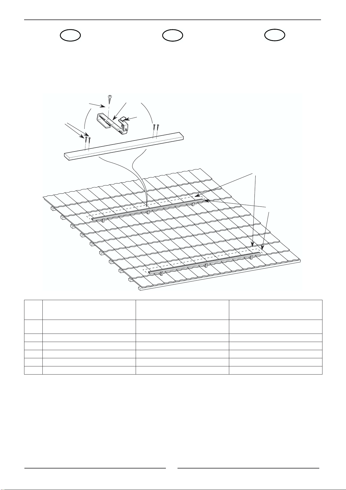
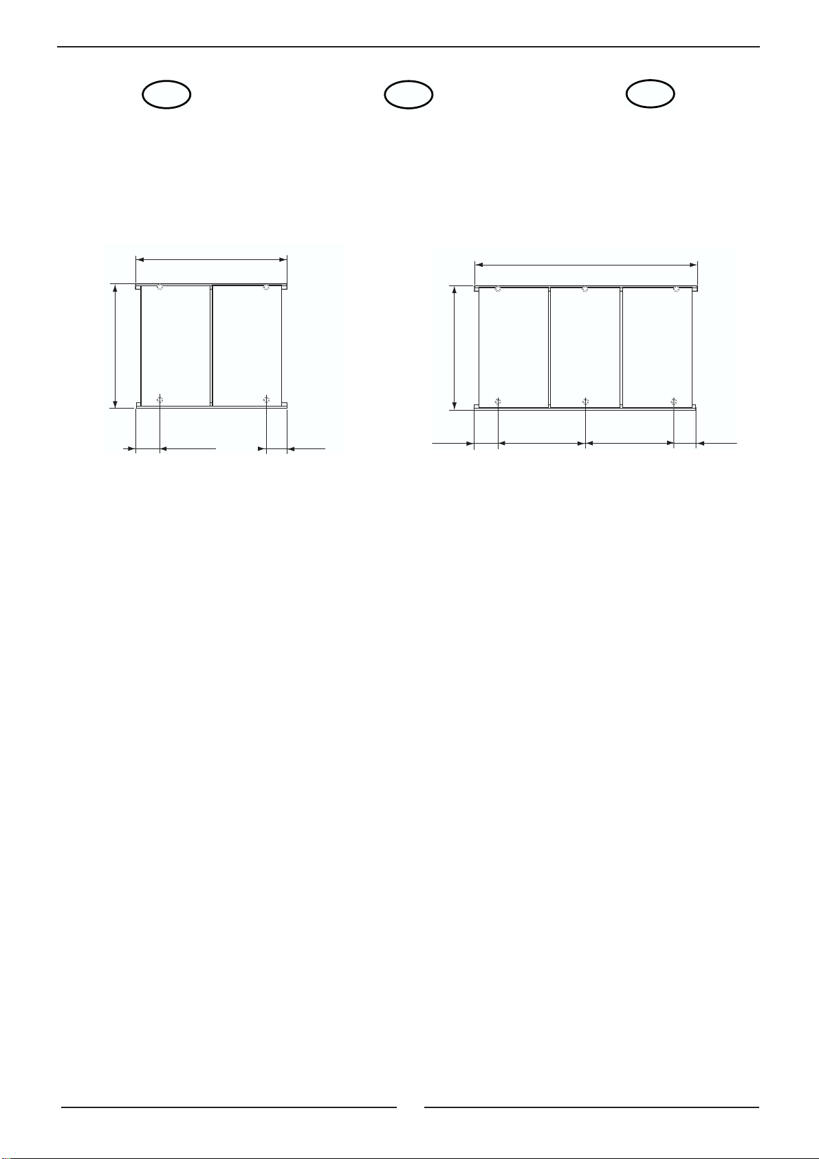
La notice de montage décrit le mon-
tage de capteurs solaires verticaux
sur des profilés de base horizon-
taux. Etant donné que les kits sont
identiques, à l'exception de la fixa-
tion des profilés de base au bâti-
ment, le montage des capteurs est
traité dans des chapitres communs.
Die Montageanleitung beschreibt
die Montage senkrecht angeordne-
ter Kollektoren auf horizontal verlau-
fenden Basis-Profilen. Da die Sets
bis auf die Befestigung der Basis-
profile am Baukörper identisch sind,
erfolgt die Kollektormontage in ge-
meinsamen Kapiteln.
The installation instructions de-
scribe the installation of vertically
mounted panels on horizontal
mounting rails. As the sets are iden-
tical except for the method of fasten-
ing the mounting rails to the
structure, installation of the panels is
described in common chapters.
FDGB

4
1.3 Instructionsrelatives
à la sécurité et sym-
boles
1.3 Sicherheitshinweise
und Symbole 1.3 Safety Instructions
and Symbols
Respecter scrupuleusement les ins-
tructions de sécurité décrites ci-
après lors de l'installation. Les sym-
boles utilisés dans ce texte sont les
suivants :
Beachten Sie bei der Montage die
Sicherheitshinweise in dieser Anlei-
tung! Nachfolgend sind die im Text
verwendeten Symbole erläutert:
Take note of the safety instructions
in this document when installing the
panels. The symbols used to identify
specific types of information are ex-
plained below.
Ce symbole indique un
danger potentiel !
Dieses Symbol weist auf
eine mögliche Gefahr
hin!
This symbol draws at-
tention to a potential haz-
ard.
Recommandation impor-
tante
Wichtige Empfehlung
Important recommenda-
tion
Information utile ou indi-
cation d'ordre général. Nützliche Information
oder allgemeiner Hin-
weis.
Useful information or
general note.
1.4 Conservation de la
notice de montage 1.4 Aufbewahrung der
Montageanleitung 1.4 Safekeeping of the
Installation Instruc-
tions
La notice de montage et d'utilisation
est à remettre à l'exploitant de l'ins-
tallation.
Ce dernier est responsable de la
conservation des instructions et as-
sure leur mise à disposition en cas
de besoin.
Die Montage- und Bedienungsanlei-
tung ist dem Anlagenbetreiber aus-
zuhändigen.
Dieser übernimmt die Aufbewah-
rung, damit die Anleitung im Be-
darfsfall zur Verfügung steht.
The Instructions for Installation and
Use must be passed to the system
operator.
The operator is then responsible for
their safekeeping so that they can
be referred to in the future if neces-
sary.
1.5 Installation 1.5 Montage 1.5 Installation
L'installation des kits de montage
sur toiture et pour toiture en terrasse
doit être réalisée par un profession-
nel qualifié. Celui-ci doit également
se conformer aux lois, aux régle-
mentations et aux normes en vi-
gueur.
Tous les travaux d'ordre électrique
doivent être réalisés par un électri-
cien spécialisé, dans le respect des
normes DTU, des directives de pré-
vention contre les accidents et des
directivesdesentreprises d'électrici-
té locales.
Die Montage der Aufdach- und
Flachdach-Montage-Sets muss von
einem entsprechend qualifizierten
Fachmann ausgeführt werden. Die-
ser ist auch verantwortlich für die
Beachtung der bestehenden Geset-
ze, Vorschriften und Normen.
Alle elektrischen Arbeiten dürfen nur
von einer Elektrofachkraft nach den
geltenden DIN-Normen, VDE-Vor-
schriften, Unfallverhütungsvor-
schriften und den Vorschriften der
örtlichen Elektrizitätsversorgungs-
unternehmen (EVU) ausgeführt
werden.
The roof-surface and flat-roof instal-
lation sets must be installed by an
appropriately qualified expert. The
installer is also responsible for com-
pliance with the applicable legisla-
tion, specifications and standards.
All electrical work must be carried
out by a qualified electrician and
must conform to the applicable
standards, specifications, safety
regulations and the requirements of
the local electricity supplier.
FDGB

5
1.6 Matériauxàposerpar
le maître d'oeuvre 1.6 Bauseitszustellende
Materialien 1.6 Equipment and Mate-
rials to be Provided
Vis de fixation pour planches de
montage / ferrures d'ancrage. Befestigungsschrauben für Monta-
gebretter / Dachanker. Fastening screws for fixing battens/
roof anchors.
Montage pour toiture en terrasse :
Si la stabilité du support n'est pas
assurée par vissage mais par lesta-
ge, les poids doivent être placés de
la manière suivante dans le cas
d'une zone soumise au vent jusqu'à
8 m de hauteur et/ou à des chutes
de neige jusqu'à 0,75 kN/m
2
:
Flachdachmontage:
Wird die Standsicherheit des Flach-
dach-Montageständers nicht durch
Verschrauben sondern durch Be-
schweren hergestellt, so müssen
die Gewichte bei einer Windlastzo-
ne bis 8 m Gebäudehöhe und einer
Schneelastzone bis 0,75 kN/m
2
wie
folgt ausgelegt werden:
Flat roof installation:
If the supporting frame is secured by
weights rather than being screwed
down, the weights must conform to
the following specifications for a
wind exposure zone covering a
building height of up to 8 m and a
snow exposure zone of up to 0.75
kN/m
2
:
Montage pour toiture en ter-
rasse jusqu'à 8 m
3 capteurs 336 kg
5 capteurs 672 kg
8 capteurs 1008 kg
Flachdach-Montage bis
8 m
3 Kollektoren 336 kg
5 Kollektoren 672 kg
8 Kollektoren 1008 kg
Flat roof installation up to 8 m.
3 panels 336 kg
5 panels 672 kg
8 panels 1008 kg
Des pierres utilisées parfois comme
bordures de pelouse peuvent servir
de poids par exemple
Als Gewichte können z. B. Rasen-
kantensteine benutzt werden. Slabs such as lawn edging stones
can be used as the weights.
1.7 Outillage nécessaire 1.7 Erforderliche Werk-
zeuge 1.7 Tools required
Les outils suivants sont nécessaires
pour le montage des kits :
- Crayon
- Mètre à ruban ou mètre pliant
- Clé à fourche 13 mm
- Clé à fourche 17/19 mm (2)
- Tournevis (plat/cruciforme)
- Clé pour vis à six pans creux de
6 mm
- Visseuse sans fil / perceuse
Folgende Werkzeuge werden für die
Montage der Sets benötigt:
- Bleistift
- Bandmaß oder Gliedermaßstab
(Zollstock)
- Gabelschlüssel 13 mm
- Gabelschlüssel 17/19 mm (2 Stck.)
- Schraubendreher (Schlitz/Kreuz-
schlitz)
- Schraubendreher für Innensechs-
kant 6 mm
- Akku-Schrauber / Bohrmaschine
The following tools are required to
install the sets:
- Pencil
- Tape measure or folding rule
- Open-ended spanner, 13 mm
- Open-ended spanner, 17/19 mm
(2 off)
- Screwdriver (flat and cross-blad-
ed)
- Allen-key driver, 6 mm
Cordless drill/power driver
FDGB

6
1.8 Normes et directives
En plus des directives cités ci-dessous, les décrets locaux doivent être pris en considération lors de l’étude, de l’ins-
tallation et de la mise en service.
- DTU 40.11 NF P32-201-1 :
Couverture en ardoises - Cahier des charges et NF P32-201-2 Partie 2 : Cahier des clauses spéciales
- DTU 40.14 NF P39-201-1 (juin 1991, mai 1993, janvier 2001) :
Couverture en bardeaux bitumés - Partie 1 : Cahier des clauses techniques et NF P39-201-2 Cahier des clauses
spéciales
- DTU 40.21 NF P31-202-1 (octobre 1997, septembre 2001) :
Couvertures en tuiles de terre cuite à emboîtement ou à glissement à relief - Partie 1 : Cahier des clauses techniques
et NF P31-202-2 Partie 2 : Cahier des clauses spéciales
- DTU 40.22 NF P31-201-1 (mai 1993, décembre 1996, janvier 1999, septembre 2001) :
Couverture en tuiles canal de terre cuite - Partie 1 : Cahier des clauses techniques et NF P31-201-2 Cahier des
clauses spéciales
- DTU 40.23 NF P31-204-1 (septembre 1996, septembre 2001) :
Couverture en tuiles plates de terre cuite - Partie 1 : Cahier des clauses techniques et NF P31-204-2 Partie 2 : Cahier des
clauses spéciales
- DTU 40.24 NF P31-207-1 (mai 1993, février 1999, juin 2001) :
Couverture en tuiles en béton à glissement et à emboîtement longitudinal - Partie 1 : Cahier des clauses techni-
ques et NF P31-207-2 (mai 1993) Partie 2 : Cahier des clauses spéciales
- DTU 40.25 (DTU P31-206) (décembre 1984, mai 1985, juin 1997, avril 2000, décembre 2000) :
Couverture en tuiles plates en béton - Cahier des clauses techniques et Cahier des clauses spéciales
- DTU 40.32 (DTU P34-201) (avril 1967) :
Couverture en plaques ondulées métalliques - Cahier des charges et Cahier des clauses spéciales
- DTU 40.35 NF P34-205-1 (mai 1997) :
Couvertureenplaquesnervuréesissues detôles d'acierrevêtues- Partie1 : Cahierdesclausestechniqueset NFP34-
205-2 Partie 2 : Cahier des clauses spéciales
- DTU 40.36 NF P34-206-1 (mai 1993) :
Couverture en plaques nervurées d'aluminium prélaqué ou non - Partie 1 : Cahier des clauses techniques et NF P34-
206-2 Partie 2 : Cahier des clauses spéciales
- DTU 43.1 NF P84-204-1 (juillet 1994, mars 2001) :
Travaux d'étanchéité des toitures-terrasses avec éléments porteurs en maçonnerie - Cahier des clauses techniques et
NF P84-204-2 Cahier des clauses spéciales
- DTU 43.2 NF P84-205-1 :
Étanchéité des toitures avec éléments porteurs en maçonnerie de pente supérieure ou égale à 5 % - Cahier des clau-
ses techniques Et NF P84-205-2 Cahier des clauses spéciales
- DTU 43.3 NF P84-206-1 (juin 1995) Mise en œuvre des toitures en tôles d’acier nervurées avec revêtement d’étan-
chéité - Cahier des clauses techniques et NF P84-206-2. Cahier des clauses spéciales. Juin 1995
- DTU 43.4 NF P84-207-1 (mai 1993, décembre 1995) : Toitures en éléments porteurs en bois et panneaux dérivés du
bois avec revêtements d'étanchéité - Partie 1 : Cahier des clauses techniques et NF P84-207-2 (mai 1993) Partie 2 :
Cahier des clauses spéciales
- DTU 59.1 NF P74-201-1 (DTU 59.1) (octobre 1994, octobre 2000) : Peinture - Travaux de peinture des bâtiments -
Partie 1 : Cahier des clauses techniques et NF P74-201-2 (octobre 1994, octobre 2000) Partie 2 : Cahier des clauses
spéciales
- DTU 65.12 NF P50-601-1 (mai 1993, octobre 1998, octobre 2000) : Travaux de bâtiment - Réalisation des installations
de capteurs solaires plans à circulation de liquide pour le chauffage et la production d'eau chaude sanitaire - Cahier
des clauses techniques et NF P50-601-2 Cahier des clauses spéciales.
F

7
1.8 Normen und Richtlinien 1.8 Standards and rules
Neben den folgenden allgemeingültigen Vorschriften,
Bestimmungen und Normen müssen u. U.noch regionale
Bestimmungen bei Planung, Errichtung und Inbetriebnahme
sowie die allgemein anerkannten Regeln der Technik
beachtet werden.
The German and French standards and directives cited
in the previous pages apply.
- VBG 4
Unfallverhütungsvorschriften Elektrische Anlagen und
Betriebsmittel
- VBG 37
Unfallverhütungsvorschrift Bauarbeiten
- VBG 74
Leitern und Tritte
- ZVDH, Regelwerk (Stand März 2003)
- LBOen
Landesbauordnungen der Bundesländer
- DIN 18299
Allgemeine Regelung für Bauarbeiten jeder Art
- DIN 18334
Zimmer- und Holzbauarbeiten
- DIN 18338
Dachdeckungs- und Dachabdichtungsarbeiten
- DIN 18339
Klempnerarbeiten
- DIN 18351
Fassadenarbeiten
- DIN 18360
Metallbauarbeiten, Schlosserarbeiten
- DIN 18451
Gerüstarbeiten
- DIN V EN 1991
Lastenannahme für Bauten
- DIN 4102
Brandverhalten von Baustoffen und Bauteilen
- DIN 4109
Schallschutz im Hochbau
- ZVH - Richtlinie 11.01
Einbindung solartechnischer Anlagen in die Haus-wär-
meversorgung
- DIN EN 12976
Thermische Solaranlagen und ihre Bauteile - Kun-
denspezifisch gefertigte Anlagen -
- DIN ENV 12977
Thermische Solaranlagen und ihre Bauteile - Vorge-
fertigte Anlagen -
- DIN VDE 0100
Elektrischen Anlagen
- DIN VDE 0185-1, DIN 57185-1
Blitzschutzanlage, Allgemeines für das Errichten
- DIN VDE 0190
Einbeziehung von Gas- und Wasserleitungen in den
Hauptpotentialausgleich
VDE 0855-1, DIN 57855-1
Errichtung und Betrieb (Erdung) von Antennenanlagen
DGB

8
2. ETENDUE DE LA
LIVRAISON 2. LIEFERUMFANG 2. PACKAGE
CONTENTS
Le kit de montage doit être manipulé
avec précaution lors du transport et
du stockage. Si l'emballage devait
toutefois être endommagé au cours
du trajet, le transporteur doit en être
avisé sans délai.
Avant le montage, il faut vérifier que
le kit du montage fourni comporte
bien tous les éléments.
Les emballages doivent être recy-
clés après l'installation conformé-
ment à la législation locale.
Das Montage-Set ist bei Transport
und Lagerung sorgsam zu behan-
deln. Sollte die Verpackung den-
noch auf dem Lieferweg beschädigt
worden sein, so ist der Schaden un-
verzüglich bei dem Transporteur an-
zuzeigen und geltend zu machen.
Vor der Montage ist der Lieferum-
fang des Montage-Sets auf Volls-
tändigkeit zu prüfen.
Das Verpackungsmaterial ist nach
der Installation umweltgerecht zu
entsorgen.
The installation set must be handled
carefully during transportation and
storage. If the packing has never-
theless been damaged during tran-
sit, the damage must be reported
immediately to and claimed against
the carrier.
Before installation, the package
contents of the installation sets
should be checked for complete-
ness.
The packing material should be
properly disposed of after installa-
tion.
Kit de montage sur toiture
Aufdach-Montage-Set
On-roof installation set
Kit de montage pour
toiture en terrasse
Flachdach-Montage-Se
t
Flat-roof installation se
t
Nombre de capteurs Anzahl Kollektoren Number of panels 2323
Profilés Basisprofile Mounting rails 2 x 1530
mm 2 x 2295
mm 2 x 1530
mm 2 x 2295
mm
Cales coulisseaux Nutsteine T-slot nuts 8 12 8 12
Vis à tête cylindrique :
M8 x 14 mm Zylinderschrauben:
M8 x 14 mm Cheese-head bolts:
M8 x 14 mm 812812
Vis à tête cylindrique :
M8 x 20 mm Zylinderschrauben:
M8 x 20 mm Cheese-head bolts:
M8 x 20 mm 2222
Rondelles :
A2 - 8,4 mm Unterlegscheiben:
A2 - 8,4 mm Washers:
A2 - 8.4 mm 10 14 10 14
Ecrous hexagonaux :
M8 Sechskantmuttern:
M8 Hexagon nuts: M8 2222
Planches de
montage :
30 x 90 x 2000 mm
(montage sur lattes)
Montagebretter:
30 x 90 x 2000 mm
(sparrenunabhängige
Montage)
Fixing battens:
30 x 90 x 2000 mm
(batten mounting) 2222
Notice de montage et
d'utilisation Montage- und Bedie-
nungsanleitung Instructions for instal-
lation and use 1111
Ferrures d'ancrage,
zone soumise à des
chutes de neige 1
(non incluses dans le
kit)
Dachanker,
Schneelastzone 1
(nicht im Set enthalten)
Roof anchors, snow-
load zone 1 (not
included with set) 46- -
Prolongateurs de fer-
rures d'ancrage Dachankererweiterun-
gen Roof anchor exten-
sions 23- -
Kits d'équerre de
montage pour toiture
en terrasse Flachdachwinkel-Sets Flat roof profile sets - - 2 3
Kits de traverse croix Sicherungskreuz-Sets Scissor stay set - - 1 1
FDGB
FDGB

9
3. VUE D'ENSEMBLE
DU MONTAGE DE
LA STRUCTURE
3. MONTAGEÜBER-
SICHT DER UNTE-
RKONSTRUKTION
3. OVERVIEW OF
INSTALLATION OF
THE SUBSTRUC-
TURE
Rep./
Pos./
Item Désignation Bezeichnung Description
03-A Ferrure d'ancrage ALU avec vis à
embase, rondelle dentée, écrou Dachanker ALU mit Formschluss-
Schraube, Fächerscheibe Mutter Aluminium roof anchor with interlock
bolt, serrated washer, nut
04 Profilé Basisprofil Mounting rail
10 Vis à embase Formschluss-Schraube Interlock bolt
16-A Vis à bois, longue Holzschraube, lang Wood screw, long
16-B Vis à bois, courte Holzschraube, kurz Wood screw, short
18 Planche de montage Montagebrett Fixing batten
FDGB
16-B
16-A
03-A
10
18
18
04
8980N211

10
4. MONTAGE SUR
TOITURE 4. AUFDACH-MON-
TAGE 4. ON-ROOF INSTAL-
LATION
4.1 Dimensions et
cotes de fixation des
ferrures d'ancrage
4.1 Abmessungen und
Befestigungsabs-
tände der Dachanker
4.1 Dimensions of and
spacings between
roof anchors
La position des capteurs solaires est
déterminée par la surface de toiture.
La largeur d'un capteur tubulaire est
de 765 mm.
La largeur nécessaire est donc éga-
le au nombre de capteurs multiplié
par 765 mm.
Il faut y ajouter l'espace nécessaire
aux conduits de raccordement su-
périeurs droit et gauche de la batte-
rie de capteurs. Il faut également
prévoir une tuile chatière pour le
passage des conduits de départ et
de retour.
Auf der vorgesehenen Dachfläche
ist die Lage der Kollektoren zu be-
stimmen.
Die Breite eines Röhrenkollektors
beträgt 765 mm.
Demnach ist die benötigte Breite
gleich der Kollektoranzahl mal
765 mm.
Zu beachten ist weiterhin, das die
Anschlussleitungen links und rechts
oben am Kollektorfeld angebracht
werden müssen. Die entsprechende
Lüfterpfanne zur Durchführung der
Vor.- bzw. Rücklauf- Anschlusslei-
tung ist zu berücksichtigen.
The position of the panels must be
measured on the intended roof sur-
face.
One tubular panel is 765 mm wide.
Accordingly, the width of roof re-
quiredisequalto the numberofpan-
els multiplied by 765 mm.
It must also be noted that the supply
pipes have to be mounted to the top
left and right of the solar-panel
space. Take note of the requirement
for a ventilation tile through which
the supply and return pipes can
pass.
FDGB
3 capteurs
avec indications des écarts des supports
3 Kollektoren
mit Angabe der Dachankerabstände
3 panels
showing roof-anchor spacings.
2 capteurs avec écarts des supports
2 Kollektoren mit Angabe der Dachankerabstände
2 panels showing roof-anchor spacings.
max.400 max.400
1530
A
8980N213
max.
400 max.
500
2295
~ 750~ 750
A
8980N214
A : 1670 (entraxe profilé / Achsabstand Basisprofil / mounting rails spacing)
1550 à 1800 (entraxe ferrure d’ancrage / Achsabstand Dachanker / roof-anchors spacing)

11
4.2 Choix des ferrures
d'ancrage 4.2 AuswahlderDachan-
ker 4.2 Selection of the roof
anchors
Deux types de ferrures d'ancrage
différents sont disponibles pour la
fixation des profilés :
Zur Befestigung der Basisprofile
stehen zwei unterschiedliche
Dachanker zur Verfügung:
There are two different types of roof
anchor for fixing the solar-panel
mounting rails:
●
Type (03A) : montage sans
chevrons
Matériau : aluminium
Code commande :
- EG 311 pour 2 capteurs tubulaires
- EG 312 pour 3 capteurs tubulaires
Pour les toits en tuiles, des planches
de montage supplémentaires sont
fixées à la charpente du toit. Les fer-
rures d'ancrage sont accrochées et
fixées à la planche de montage
(montage
sur lattes
).
●
Typ (03A): sparrenunabhängi-
ge Montage
Material: Aluminium
Bestellnummer:
- EG 311 für 2 Röhrenkollektoren
- EG 312 für 3 Röhrenkollektoren
Bei Dächern mit Pfannen-
eindeckung werden zusätzliche
Montagebretter an der Dachunter-
konstruktion befestigt. Die Dach-
anker werden in das Montagebrett
eingehängt und befestigt (spar-
ren
unabhängige
Montage).
●
Type (03A): batten-mounted
type
Material: aluminium
Order number:
- EG 311 for 2 tubular solar panels
- EG 312 for 3 tubular solar panels
On tiled roofs, additional fixing bat-
tens are added to the roof substruc-
ture. The roof anchors are hooked
over the fixing battens and fixed to
them (
batten-mounted
anchors).
●
Type (03B) : montage sur che-
vrons
Matériau : acier allié
Code commande :
- EG 313 pour 2 capteurs tubulaires
- EG 314 pour 3 capteurs tubulaires
Pour les toits en tuiles, ces ferrures
d'ancrage sont directement fixées
sur les chevrons de toit (montage
sur chevrons
).
●
Typ (03B): sparrenabhängige
Montage
Material: Edelstahl
Bestellnummer:
- EG 313 für 2 Röhrenkollektoren
- EG 314 für 3 Röhrenkollektoren
Bei Dächern mit Pfanneneindeck-
ung werden diese Dachanker
direkt auf den Dachsparren befes-
tigt (sparren
abhängige
Montage).
●
Type (03B): rafter-mounted
type
Material: stainless steel
Order number:
- EG 313 for 2 tubular solar panels
- EG 314 for 3 tubular solar panels
On tiled roofs, these roof anchors
are attached directly to the roof raft-
ers (
rafter-mounted
anchors).
FDGB
8980N162
8980N163
Typ (03B)
Typ (03A)

12
4.3 Utilisation de ferrures d'ancrage
sans
fixation sur chevrons 4.3 Verwendung von Dachankern
ohne
Sparrenbefestigung
Ne fixez jamais votre harnais de sécurité au
système de montage ! Les harnais de sécu-
rité doivent toujours être fixés à des parties
du toit pouvant supporter la charge, comme
les chevrons, par exemple. Votre harnais de sécurité
doit toujours être fixé sur les chevrons, à droite ou à
gauche au-dessus des capteurs.
Sicherheitsgurte nie am Montage-System
befestigen! Sicherheitsgurte müssen immer
an belastbaren Dachteilen, z. B. den Spar-
ren, befestigt werden. Die Sicherheitsein-
richtung sollte immer über den Kollektoren rechts oder
links an den Sparren befestigt werden.
1. Dégager la surface de montage (longueur de la
planche de montage). 1. Die Montagefläche (Länge des Montagebretts) frei-
legen.
Il suffit généralement de soulever les tuiles. Das Hochschieben der Dachsteine reicht in
der Regel aus.
2. Pour le montage des ferrures d'ancrage, visser les
planches de montage (18) sur les chevrons avec un
écart de 160 mm par rapport au lattis inférieur (32).
2. Zur Montage der Dachanker werden die
Montagebretter (18) mit 160 mm Abstand zur unter-
en Dachlatte (32) auf den Sparren geschraubt.
L'écart de 160 mm dépend des ferrures
d'ancrage et de la couverture. Il doit être
adapté si nécessaire.
Der Abstand von 160 mm ist abhängig von
Dachanker und Eindeckung und muss
gegebenenfalls angepasst werden.
L'écart des planches de montage (A) les unes par
rapport aux autres doit être compris entre 1550 à
1800 mm. (mesuré du bord supérieur au bord supé-
rieur). Si l'écart est inférieur à 1670 mm ou supé-
rieur à 1720 mm, l'usage de prolongateurs de
ferrures d'ancrage est nécessaire.
Der Abstand der Montagebretter (A) untereinander
muss 1550 bis maximal 1800 mm betragen. (Ober-
kannte - Oberkannte gemessen). Ist der Abstand
kleiner als 1670 mm oder größer als 1720 mm, so
ist der Einsatz von Dachankererweiterungen er-
forderlich.
Les planches de montage doivent être posées pa-
rallèlement et à distance régulière, et vissées aux
chevrons.
Die Montagebretter werden parallel in gleich-
mäßigem Abstand verlegt, und mit dem Dachspar-
ren verschraubt.
F
D

13
4.3 Use of roof anchors
with batten mounting
Never attach safety harnesses to the
mounting system. Safety harnesses must
always be attached to roof members capa-
ble of taking the weight, e.g. the rafters. The
safety equipment should always be attached to the raft-
ers to the left or right of and above the solar panels.
1. Expose the area for the installation (length of the fix-
ing batten).
It is usually sufficient simply to slide the roof
tiles upwards.
2. The fixing battens (18) are screwed to the rafters at
a distance of 160 mm from the roof batten (32) be-
low to install the roof anchors.
The distance of 160 mm depends on the
roof anchor and the roof covering and may
have to be modified to suit.
The fixing battens (A) must be spaced at a distance
of 1550 to 1800 mm from one another (measured
top edge to top edge). If the distance is less than
1670 mm or is greater than 1720 mm, it will be nec-
essary to use roof anchor extensions.
The fixing battens are laid parallel at a uniform dis-
tance and are screwed onto the rafter.
GB
79
62,5
¿6
145
40
99
278
8980N212
Vertikal Abstand
Horizontal fluchtend
Horizontal Abstand
Vertikal fluchtend
Espace horizontal Alignement horizontal
Espace vertical
Alignement vertical
Horizontal distance Horizontally flush
Vertical distance
Verticall
y
flush
8980N216
A160
32
18
18
A = 1550 - 1800

14
3. Accrocher la ferrure d'ancrage (03-A) dans le creux
de tuile et dans la planche de montage puis la fixer
avec une vis (16 B).
3. Den Dachanker (03-A) im Pfannental in die Mon-
tagebretter einhängen und mit Schraube (16-B) be-
festigen.
La position horizontale des ferrures d'ancra-
ge dépend des creux des tuiles. Die horizontale Position der Dachanker ist
von den Pfannentälern abhängig.
4. Monter toutes les autres ferrures d'ancrage en sui-
vant le même procédé.
Les ferrures d'ancrage doivent être montées avec
un espacement uniforme sur toute la longueur de la
planche de montage.
Espacements des ferrures d'ancrage :
voirchapitre4.1 Dimensions et cotesdefixation des
ferrures d'ancrage, page 10
4. Alle weiteren Dachanker in gleicher Weise befesti-
gen.
Die Dachanker werden auf die gesamte Länge des
Montagebrettes bezogen mit gleichmäßigem Ab-
stand montiert.
Dachankerabstände:
siehe Kapitel 4.1 Abmessungen und Befesti-
gungsabstände der Dachanker, Seite 10
Les ferrures d'ancrage doivent être parfaite-
ment alignées dans le sens horizontal et
vertical (suivre les creux de tuile).
Die Dachanker sollen horizontal und vertikal
fluchtend montiert sein (Pfannentäler der
Dachsteine beachten).
5. Fermer la couverture du toit en haut et en bas. 5. Die Dachhaut oben und unten schließen.
6. Vérifier l'écartement et, le cas échéant, monter une
section de prolongation sur la ferrure d'ancrage in-
férieure.
Pour cela :
Démonter le boulon à tête rectangulaire de la ferru-
re d'ancrage,
Visser le prolongateur de ferrure d'ancrage à
l'équerre avec des vis à tête cylindrique M8 x 20,
des rondelles et des écrous
Ensuite, monter le boulon à tête rectangulaire dans
les trous oblongs correspondants.
6. Abstandsmaß überprüfen und gegebenenfalls Ver-
längerungsprofil auf den unteren Dachanker mon-
tieren.
Hierzu :
Hammerkopfschraube vom Dachanker demontier-
en,
Dachankererweiterung mit Zylinderschrauben
M8 x 20, Unterlegscheiben und Muttern am Winkel
festschrauben
Anschließend Hammerkopfschraube in den
entsprechenden Langlöchern montieren.
F
D

15
3. Hook the roof anchor (03A) over the fixing batten in
line with a tile valley and fix in place with a screw
(16-B).
The side by side positioning of the roof an-
chors is dependent upon the tile valleys.
4. Fix all remaining roof anchors in the same manner.
The roof anchors are fitted at uniform intervals de-
termined over the full length of the fixing batten.
Roof anchor spacing:
see chapter 4.1 Dimensions of and spacings be-
tween roof anchors, page 10
The roof anchors should be aligned flush
horizontally and vertically (follow roof-tile
valleys).
5. Replace the roof tiles top and bottom.
6. Check the distance and fit an extension profile on
the lower roof anchor where necessary.
To do this:
Remove the hammerhead screw from the roof an-
chor,
Fasten the roof anchor extension to the profile with
M8 x 20 cheese-head bolts, washers and nuts
Then fit the hammerhead screw into the corre-
sponding slotted holes
GB
b
16-A 16-B
03-A
18
32
160mm
31
29
8980N215
8980N218
8980N217

16
4.4 Montage des profilés (capteurs jux-
taposés) 4.4 Montage der Basisprofile
(Kollektoren nebeneinander)
1. Monter le profilé (04) sur les ferrures
d'ancrage (03).
Pourcefaire, positionner latête de lavisà encastrer
(10)parallèlement auprofilé(04)etposer leprofilé .
Soulever les vis à encastrer de la ferrure d'ancrage
(03) et les bloquer en tournant de 90° (). Celles-ci
doivent être ajustées avant le serrage. Serrer ensui-
te légèrement les écrous des vis à encastrer. Utili-
ser les rondelles dentées pour bloquer les écrous.
1. Das Basisprofil (04) auf die Dachanker (03) mon-
tieren.
Dazu die Schraubenköpfe der Formschluss-
Schrauben (10) parallel zum Basisprofil (04) stellen
und das Basisprofil auflegen.
Die Formschluss-Schrauben im Dachanker (03)
nach oben schieben und mit 90˚-Drehung () sich-
ern. Diese müssen vor dem Festschrauben ausger-
ichtet werden. Anschließend die Muttern der
Formschluss-Schrauben leicht festziehen. Zur
Sicherung der Muttern die Fächerscheiben ver-
wenden.
2. Aligner les profilés horizontalement et verticale-
ment,desorte que lesprofilés et lestuilessoient pa-
rallèles. Les diagonales entre les profilés de base
doivent être de dimensions identiques :
D1 = D2
A l'aide des trous oblongs, fixer les profilés de base
à une distance de 1670 mm de centre à centre.
Serrer les écrous des vis à encastrer après ajuste-
ment.
3. Montage des capteurs :
voir chapitre 6. Montage du capteur solaire,
page 26
2. Basisprofile horizontal und vertikal so ausrichten,
dass Profile und Dachsteine parallel zueinander
verlaufen. Die Diagonalmaße zwischen den Basis-
Profilen müssen gleich sein:
D1 = D2
Mit Hilfe der Langlöcher das Basisprofil-Abstand-
maß auf 1670 mm Mitte-Mitte Profil fixieren.
Die Muttern der Formschluss-Schrauben nach aus-
richten festziehen.
Montage der Kollektoren:
siehe Kapitel 6. Kollektor-Montage, Seite 26.
F
D

17
4.4 FIXING THE MOUNTING RAILS
(panels side by side)
1. Fit the mounting rail (04) onto the roof anchors (03).
To do so, turn the heads of the interlock bolts (10)
parallel to the mounting rail (04) and place the
mounting rail over them.
Push the interlock bolts upwards through the roof
anchor (03) and turn through 90° () to secure.
These bolts must be aligned before they are tight-
ened. Then finger-tighten the nuts on the interlock
bolts. Remember to fit the serrated washers to the
interlock bolts.
2. Align the mounting rails horizontally and vertically
so that the rails run parallel to the roof tiles. The di-
agonals between the mounting rails must be equal,
i.e.
D1 = D2
Use the slotted holes to set the mounting rail centre-
to-centre distance to 1670 mm.
Tighten the nuts on the interlock bolts after the rails
have been aligned.
Fitting the panels:
see Kapitel 6. Kollektor-Montage, Seite 26.
GB
04
10
03
8980N219
8980N220
D1
D2
1670

18

19
5. MONTAGE POUR
TOITURE EN TER-
RASSE
5. FLACHDACH-MON-
TAGE 5. FLAT-ROOF
INSTALLATION
5.1 Dimensions et
cotes de fixation des
équerres du kit de
montage
5.1 Abmessungen und
Befestigungsabs-
tände der Flachda-
chwinkel
5.1 Dimensions of and
spacings between
flat-roof iron corners
*Unetraverse croix doitêtremontée
dans cette zone ; par conséquent, il
est impératif de respecter scrupu-
leusement la cote indiquée.
* In dieses Feld wird ein Sicherungs-
kreuz eingebaut, deshalb ist das
Maß genau einzuhalten.
* A scissor stay is fitted in this area,
the measurement must therefore be
precise.
FDGB
3 capteurs
3 Kollektoren
3 panels
2 capteurs
2 Kollektoren
2 panels
1530
=1020*
1670
~ 250~ 250
8980N221
2295
=1020*
=1020
1670
~ 75~ 75
8980N222A

20
5.2 Montagedusupportinclinablepour
installation en toiture terrasse 5.2 Flachdachständer-Montage
Pour éviter d'endommager la couverture, il
est recommandé d'utiliser un film protecteur
(tapis de protection) comme base pour le
support. Poser cette protection avant de
commencer le montage.
UmeineBeschädigung der Dachhautzuve-
rhindern, wird die Verwendung von Da-
chhautschutzfolie (Bautenschutzmatten) als
Unterlage für den Flachdachständer empfo-
hlen. Dieser Schutz ist vor Montagebeginn auszulegen.
1. Poser les profilés (04) sur la zone de montage, la
rainure large orientée vers le haut.
Espacement des profilés :
- 1670* mm perçage inférieur
1. Die Basisprofile (04) mit der breiten Nut nach oben
auf die Montagefläche legen.
Basisprofilabstand:
- 1670* mm untere Borung
2. Déplier la première équerre de montage prémontée
et poser le profilé en Llong sur les profilés de ma-
nière à ce que le profilé en Tsoit orienté vers l'inté-
rieur.
Ecartement a : voir chapitre 5.1 Dimensions et co-
tes de fixation des équerres du kit de montage,
page 19
2. Den ersten vormontierten Flachdach-Mon-
tagewinkel aufklappen und das lange L-Profil auf
die Basisprofile legen, so dass das T-Profil nach
hinten zeigt.
Abstandsmaß a: siehe Kapitel 5.1 Abmessungen
und Befestigungsabstände der Flachdachwinkel,
Seite 19
3. Fixer l'équerre de montage sur le profilé à l'aide des
vis à encastrer (10), des rondelles en éventail (25)
et des écrous (26) fournis.
3. Den Flachdach-Montagewinkel mit den beiliegend-
en Formschlussschrauben(10),
Fächerscheiben (25) und Muttern (26) am Ba-
sisprofil befestigen.
Bloquer les vis à encastrer dans le profilé en
les tournant de 90° (). Die Formschluss-Schrauben müssen durch
verdrehen um 90˚ () im Basisprofil gesi-
chert werden.
4. Positionner l'équerre de montage suivante sur les
profilés et la fixer avec les griffes de serrage. Ne pas
serrer les vis à fond, car il pourra être nécessaire
d'ajuster la position de l'équerre par la suite.
Ecartement b :
voirchapitre5.1 Dimensions et cotesdefixation des
équerres du kit de montage, page 19.
4. Den nächsten Flachdach-Montagewinkel auf die
Basisprofile legen und mit den Formschluss-
Schrauben fixieren. Die Schrauben nicht fest anzie-
hen, da ein Nachjustieren des Flachdach-Mon-
tagewinkels erforderlich werden kann.
Abstandsmaß b :
siehe Kapitel 5.1 Abmessungen und Befesti-
gungsabstände der Flachdachwinkel, Seite 19.
F
D
Table of contents
Other DeDietrich Solar Panel manuals