Siliken Photovoltaic User manual

california
california
Siliken California Corporation 1225 Exposition Way, Suite D-160 San Diego, CA92154. USA
Te .: 619-671-0246 - Fax: 619-710-4903 si iken.usa@si iken.com www.si ikenusa.com
Edition 09C Date: 05/06/2010
Photovo taic modu e
Instructions for use
SILIKEN appreciates your support for our products.
We recommend that you read this instruction manual carefully in its entirely before handling the photovoltaic module.
You will find a digital version of this catalog at www.siliken.com
We have printed this for our customers on paper that
guarantees the smallest environmental impact, and that
has obtained the following ecological certifications:
P
R
O
C
E
S
S
E
D
C
H
L
O
R
I
N
E
-
F
R
E
E
PCF
Processed Chlorine Free
Recycled
Forestry Stewardship Council
FSC
©
Renewable Power

Table of contents
Important safety instructions
Product description
Recommendations for use
Product certificates and guarantee
By pass diodes
Operating voltage
Protection fuses
Warnings and electrical hazards
Current voltage curves
Mechanical assembly instructions
Module maintenance
Module frame grounding
Declaration of CE conformity
........................................................................
.......................................................................................
..........................................................................
...............................................................
..........................................................................................
......................................................................................
.........................................................................................
..................................................................
...............................................................................
...............................................................
..................................................................................
.............................................................................
.......................................................................
3
4
6
8
10
13
14
16
20
22
33
35
41
1
2
3
4
5
6
7
8
9
10
11
12
13

Safety instructions
Instructions for using photovoltaic modules
3
This instruction manual and the product labels contain a series of important
safety messages. They should be read carefully before handling or connecting
the photovoltaic module since the module produces electricity as soon as the
cells are exposed to sunlight.
The safety warning symbol is shown before each safety message included in
this instructions manual. This symbol indicates that there is a personal safety
hazard which would affect both you and others and cause damage to the
products or other property.
This user manual must not contradict any regulation that could have changed
since the manual
s last publication date.
The last version of this manual is
available at
www.siliken.com
Warning: any fault in the module caused by failure to comply with the
warnings stipulated in this instructions manual will lead to the complete
withdrawal of the modules guarantee together with the full exoneration
of SILIKEN from any responsibility derived of any kind.
!
!
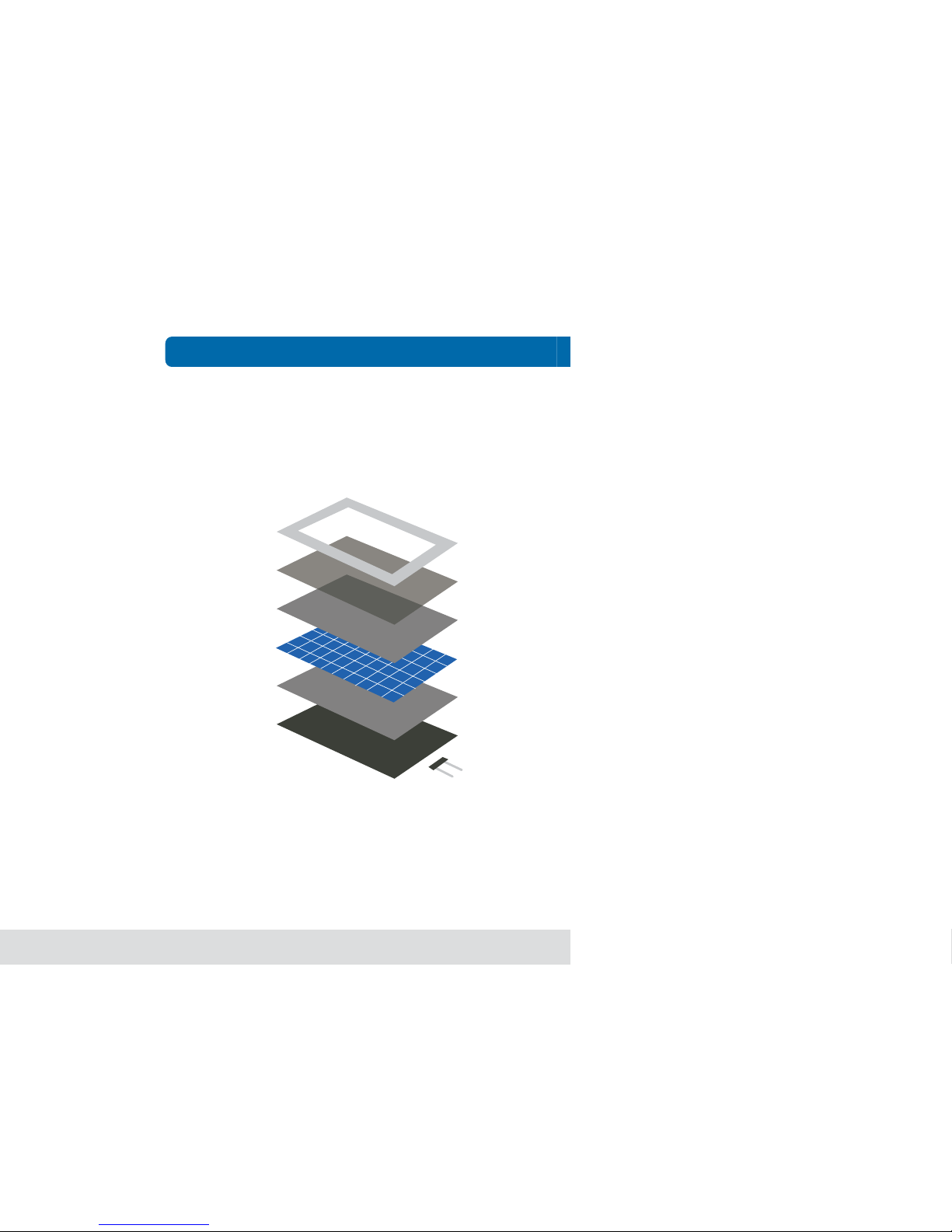
Your photovoltaic Standard module is comprised of the following elements:
1 FRAME
In anodised aluminium; providing a system for anchoring the module
to the support structure.
2 GLASS
Ultra transparent 3.2 mm thick tempered glass; providing rigidity to the
unit and protecting the active surface of the cells.
3 and 5 EVA
(Ethylene Vinyl Acetate); its function is to encapsulate the cell circuit
4 CELLS
Highly efficient crystalline silicon solar cells. These generate the electricity.
6 BACK ISOLATION SHEET
Providing electrical insulation to the rear surface of the module.
7 CONNECTION BOX.
IP65 specification. Providing a simple method of electrically connecting
the module to the rest of the installation.
Product description
4
Instructions for using photovoltaic modules
1
2
3
4
5
6
7

Your photovoltaic Glass Glass module is comprised of the following
elements:
1 FRONT GLASS
Ultra transparent 4mm thick tempered glass; providing rigidity to the unit
and protecting the active surface of the cells.
2 AND 4 EVA
(Ethylene Vinyl Acetate); its function is to encapsulate the cell circuit.
3 CELLS
Highly efficient crystalline silicon solar cells. These generate the electricity.
5 REAR GLASS
Transparent 4mm thick tempered glass.
6 CONNECTION BOX.
IP65 specification. Providing a simple method of electrically connecting
the module to the rest of the installation.
Product description
5
Instructions for using photovoltaic modules
1
2
3
4
5
6

Ensure that the module is located appropriately: it must not be placed
beneath the shade of streetlights, trees, other buildings or even shade
produced by other modules. Electricity production can be considerably
reduced by the effect of shade.
Install the PV module allowing air to circulate freely (see also section 6
of this manual). This will facilitate the natural ventilation of the module.
The module is designed to work in temperatures between 40
ºC and
+85ºC ( 40ºF and +185ºF).
In addition, both polycrystalline and
monocrystalline modules produce more energy in lower temperatures.
Therefore, proper ventilation favors higher power generation.
It is important to orient the active surface of the modules towards the
south as much as possible in the northern hemisphere, and towards the
north as much as possible in the southern hemisphere.
The metal support structure for the photovoltaic modules should be
connected to ground in the manner indicated in the Low Voltage Directive
93/68/EEC and 2006/95/EEC and National Electrical Code.
Ensure that the cables of the installation that connect modules to other
modules, as well as those that lead to the load regulator, batteries or
any other part of the installation, are not too tight since this could damage
module connections or the cables themselves. Use cable ties or cable
clamps to fix the cables to the structure.
Do not leave connectors unplugged for long periods of time; dirt may
Recommendations for use
6
Instructions for using photovoltaic modules

prevent subsequent connection. We recommend that the modules are
connected in short circuit to avoid this.
Respect the electrical polarity of the modules. You must remember that
they are direct current modules and, as such, direct current is required
for their correct operation. In addition, when connecting the different
components of an isolated installation, you must always connect the
batteries first, followed by the module, and finally the power supply.
Do not use the connection box or the connection cables to hold or
transport the module. You could damage some of its components and
affect its waterproofness as well as the electrical security.
Always handle the module with care, even if it has the aluminium frame.
Any blow on the glass or on a corner of the frame could deform it enough
to break the glass.
Do not dismantle, modify or adapt the PV module. Do not remove any
part or the identification label from a PV module installed by Siliken
Modules S.L.U. If you do so, the guarantee will be invalid. Do not apply
paint or adhesives to the back side of the PV module.
WARNING: SILIKEN shall not be held responsible or liable for any
possible decrease in the electricity production of the photovoltaic
module supplied nor shall it consider said reduction to be a
manufacturing defect if it is the result of the failure to observe the
recommendations for use described herein.
!
Recommendations for use
7
Instructions for using photovoltaic modules
Product certificates and guarantee
Siliken photovoltaic standard ang glass glass modules have been designed
and manufactured in accordance with (IEC) EN 61215 UL 1703 standards
and complies with the safety standards Qualification of photovoltaic
modules IEC61730 class A (class II). In order to comply with these
international standards, high quality and durable materials have been
used. In addition, Siliken has a series of rigorous quality controls
established for each phase of the production process along with a final
quality control of the output power for all manufactured modules. Siliken
photovoltaic glass glass modules are tested according to EN:14449.
Siliken provides a 10 year guarantee for the materials of the photovoltaic
module and against any possible defects of the photovoltaic module
due to the manufacturing process.
Product certificates and guarantee
8
Instructions for using photovoltaic modules
Periodic inspection
Qualified, IEC 61215
Safety Tested, IEC 617 0
I
I
I
I
I
I
I
I
I
I
I
I
I
I
w
w
w
.
t
u
v
.
c
o
m
I
D
:
0
0
0
0
0
2
2
3
3
5
I
I
I
I
I
I
I
I
I
I
I
I
I
I
TÜVRheinland
3NS
LISTED

Siliken also guarantees output power from the photovoltaic module of
at least 90% of the minimum output power measured under standard
conditions (STC=92.94 W/ft2 77ºF ±36ºF 1.5 Air mass / STC=1000
W/m 25ºC ±2ºC 1.5 Air mass) and specified in the Siliken products
technical documentation for 10 years.
Moreover, Siliken guarantees output power from the photovoltaic module
of at least 80% of the minimum output power measured under standard
conditions (STC=92.94 W/ft2 77ºF ±36ºF 1.5 Air mass / STC=1000
W/m 25ºC ±2ºC 1.5 Air mass) and specified in the Siliken product
technical documentation for 25 years.
Product certificates and guarantee
9
Instructions for using photovoltaic modules

By-pass diodes
10
Instructions for using photovoltaic modules
The photovoltaic module must be protected with by pass diodes. The
absence of these diodes could cause the photovoltaic module to
malfunction or even ultimately lead to its destruction as it could catch
on fire. Siliken delivers its modules with by pass diodes included inside
the connections box.
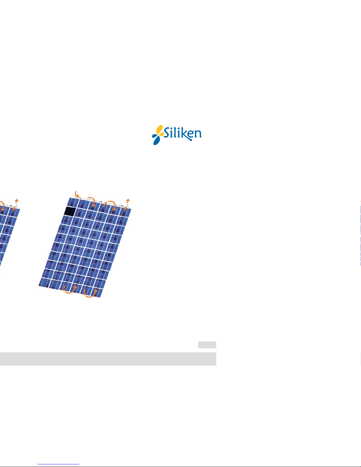
The photovoltaic cells have two operating modes: it operates as a current
generator or as a current consumer. A cell exposed to solar radiation
provides a current ranging between 6 and 8 amps with a potential
difference of around 0.6 volts. However, when a cell is partially shaded,
by the leaves of a tree for example, it starts to consume the electricity
generated by the other cells to which it is connected. At the area of the
cell that changes from a sunlit area to a shaded area, an effect known
as a "hot spot" occurs whereby, due to the circulation of current, the
overheating produced is such that it may set the materials on fire and
destroy the module. The maximum number of cells connected in series
per diode is 18 cells for SLK36P6L modules and 20 cells for SLK60P6L
and 60M6L modules.
By-pass diodes
11
Instructions for using photovoltaic modules
Normal operation Operation with the cell in the shade

WARNING: For the aforementioned reasons it is important that the
diodes are not removed from the connection box.
In the event of by pass diode failure, they must be replaced with original
by pass diode spares and by personnel authorized and trained by Siliken.
From the moment that the failure in the diodes occurs and until they are
replaced, the affected photovoltaic module(s) must remain disconnected
from the other modules on the photovoltaic array, thus guaranteeing that
the circuit remains open. In any event, the decision to change the diodes
is the responsibility of Siliken.
WARNING: Failure to use original spares or parts replaced by
personnel without the authorisation of SILIKEN etc. shall lead to
the withdrawal of the guarantee of the photovoltaic module and
SILIKEN shall automatically be exonerated from any responsibility
for damage caused to property or harm caused to people.
By-pass diodes
12
Instructions for using photovoltaic modules
!
!
Maximum system voltage
V
oc77°F
+ (( Ta - 77 ) x
no cell
x (-0.00215))
Max. no. of modules
The maximum voltage of the system is 1000 V in Europe (see module
label) and 600 V in USA (see module label). The maximum number of
modules to be connected in series (in cell temperature conditions of
77ºF / 25°C),
is defined in the electrical data tables of the modules
data
sheets.
WARNING: the value for the maximum number of modules must be
corrected based their location and in accordance with the correction
parameters provided in the formula since the voltage increases as
the temperature decreases. Calculate the value based on the lowest
temperature in the region where the modules will be installed.
Operating voltage
13
Instructions for using photovoltaic modules
!

Attention: Under normal conditions a photovoltaic module is likely
to experience conditions that produce more current and/or voltage
than reported at standard test conditions. Accordingly the values
of ISC and VOC marked on this module should be multiplied by a
factor of 1.25 when determining component voltage ratings
conductor ampacities fuse sizes and size of controls connected
to the PV output.
Attention: Refer to Section 690-8 of the National Electrical Code
for an additional multiplying factor of 125 percent (80 percent
derating) which may be applicable.
For field connections, use minimum No.
10 AWG copper wires insulated
for a minimum of 194°F / 90 ºC.
Once the modules are connected in series to obtain the correct input
voltage for each type of inverter it is essential that protection fuses are
located between the inverter and each series. These fuses will facilitate
maintenance and control tasks, but they will mainly protect the series
from each other should the polarity of one of the series of modules be
incorrectly connected.
Series fuse (overcurrent protection) rating of 15 A.
Protection fuses
14
Instructions for using photovoltaic modules
!
!

Protection fuses
15
Instructions for using photovoltaic modules
!
The design level current for these fuses must be multiplied by a factor
of 1.25 times the Isc of the photovoltaic module measured under standard
test conditions (92.94 W/ft2 and 77 ºC) / (1,000 W/m2 and 25°C). The
fuses must be suitable for direct current systems, with a breaking
capacity greater than the sum of the intensities of the series of connected
modules, using the method indicated in the National Electrical Code.
Failure to install this type of protection, in the event of an incorrect
positive and negative polarity connection, will cause the reversed series
to act as an electricity receiver causing severe damage to both the
diodes and the other electrical components of the modules.
WARNING: Failure to comply with the provisions of this section will
lead to the loss of guarantee and the exoneration of Siliken from any
type of responsibility for damage to property or injury to people.

The installation, handling and maintenance of the photovoltaic modules
must be carried out by qualified personnel duly equipped with individual
protections.
For information purposes, these protections include: safety boots with
insulation for above 1000V, gloves with 1000V insulation, as well as a
helmet and appropriate clothes.
Contact with VAC (VDC) voltage equal or higher than 30 V is potentially
dangerous. Do not use PV modules with different electrical or physical
configurations in a single PV system. Keep children away from the system
and the PV modules during installation. Do not carry out the installation
in heavy rain or wind.
For handling electrical components, always use appropriate tools covered
with insulating materials. It is recommended to avoid handling modules
in humid conditions. Before handling and installing PV modules, remove
your rings and other metal jewels.
It is important to remember that the active front panel of the module is
made of glass and can break if it receives an impact. In cases of broken
glass, the module must not be installed as it will have lost the electrical
insulation of the cells and will have a much lower performance level.
Warnings and electrical hazards
16
Instructions for using photovoltaic modules

Do not allow objects to fall on the photovoltaic module, and do not sit on,
lean on,
or walk on the photovoltaic module, on either side (glass or rear
sheet), given that it could cause the cells to break and therefore significantly
lower the power and energy performance of the modules.
Do not open the connection box of the photovoltaic module. The cover
of the connection box has a safety seal to guarantee to the customer
that it has been correctly sealed to provide IP65 level of protection. If
the cover is not correctly sealed, there is a risk of damage to the module
due to water ingress.
Do not disconnect the terminals of the modules if they are electrically
connected to other devices of the system. Before loosening connectors,
disconnect the modules from the inverter or the battery charger using
switches. Before handling any electrical parts of the PV installation,
cover the active surface of the module from sun light.
Do not use mirrors or magnifying lenses to concentrate light on the PV
modules, they were not designed for this.
When handling and installing the module, we recommend covering the
active surface of the photovoltaic module since the modules generate
electricity when they are exposed to any source of light even when they
are not connected to any other device.
Warnings and electrical hazards
17
Instructions for using photovoltaic modules

Do not remove any of the modules components or remove the technical
specifications label.
Do not place the installation near to any possible source of inflammable
gases or vapors, since the photovoltaic modules can cause sparks just
like any other electrical component.
Always ensure the installation is equipped with protection devices against
electrical hazards.
Remember that when the modules are connected in series, the voltage
present will be the sum total of the voltage from each module, and when
the modules are connected in parallel, the current present will be the
sum total of the current from each module. This means that an installation
with various modules may contain high levels of voltage and current.
When screwing the frame of the module to the structure, avoid rubbing
against the plastic insulation on the rear surface of the module (Tedlar)
with the tool or elements protruding from the structure because this
could cause the plastic to tear, causing a loss of electrical insulation.
The PV module produces power even with a broken glass or back sheet.
Do not dispose of the module in containers or dumping sites, this can
be dangerous. If the glass or the back sheet is broken, in case of
Warnings and electrical hazards
18
Instructions for using photovoltaic modules

!
electrical failure or if the service life of the module ends due to any cause
in general, please contact Siliken to appropriately eliminate and/or recycle
the product according to American/European norms.
Consult the fire security regulations, norms and prerequisites for buildings
and structures with your local authorities. Keep in mind that a roof top
construction and installation may affect the building
s fire security; erroneous
installation of PV modules can increase this risk in case of fire.
WARNING: Failure to comply with the provisions of this section
will lead to the loss of guarantee and the exoneration of Siliken
from any type of responsibility for damage to property or injury to
people.
Warning and electrical hazards
19
Instructions for using photovoltaic modules
Table of contents
Other Siliken Solar Panel manuals

Popular Solar Panel manuals by other brands

STIEBEL ELTRON
STIEBEL ELTRON SOL 25 PLUS Operating and installation instructions

Solahart
Solahart REC290TP2 installation instructions

DeDietrich
DeDietrich PRO C250V Installation

Alpha
Alpha TYB002 manual

Eterbright
Eterbright CIGS-3000A1 Series Installation and safety manual

Flexopower
Flexopower SK79 instructions


