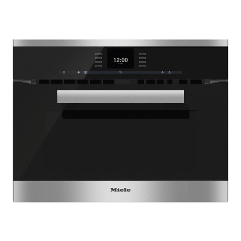
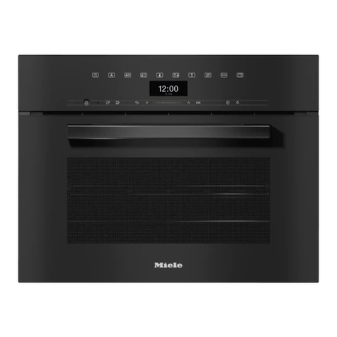
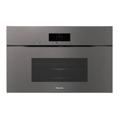
Miele H4080BM Manual

TECHNICAL INFORMATION
H4080BM Speed Oven
© 2007 Miele USA

Technical Information
H4080BM Speed Oven
H4080BM Speed Oven - Table of Contents
Safety Information ..............................................................................................7
Service Information ............................................................................................8
1.0 Construction and Design.........................................................................9
1.1 Appliance Overview................................................................................... 9
1.2 Overview of Controls ............................................................................... 10
1.3 Technical Specifications .......................................................................... 10
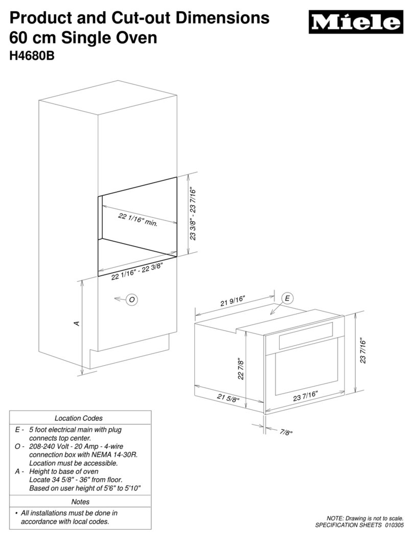
1.3.1 Appliance Dimensions ................................................................. 10
1.3.2 Electrical Specifications ............................................................... 10
1.3.3 Microwave Output Settings (Watts) ............................................. 11
1.4 Layout of Components ............................................................................ 12
2.0 Installation..............................................................................................13
2.1 General Information................................................................................. 13
2.2 Installation Procedure.............................................................................. 14
2.3 Before Using the Appliance ..................................................................... 15
3.0 Commission and Operation ..................................................................16
3.1 Functions ................................................................................................. 16
3.1.1 Solo Functions ............................................................................. 16
3.1.2 Combination Functions ................................................................ 16
3.1.3 Miscellaneous / Optional Functions ............................................. 16
3.2 General Operation ................................................................................... 17
3.2.1 Turning the Oven On ................................................................... 17
3.2.2 General Operation – Microwave Mode ........................................ 17
4.0 Description of Function.........................................................................18
4.1 Door Safety Switches .............................................................................. 18
4.2 Cooling and Vapor Ducting...................................................................... 19
4.2.1 Cooling Fan (M2/1) Specifications............................................... 19
4.2.2 Cooling Air Intake ........................................................................ 20
4.2.3 Cooling Air and Vapors Path ....................................................... 20
4.2.4 Air-Path During Microwave Operation ......................................... 20
4.2.5 Air-Path During Convection, Broiler and Combination.................20
4.2.6 Cooling Air and Vapor Exit........................................................... 20
4.2.7 Cooling Fan (Coast-Down) .......................................................... 20
4.3 Microwave Operation............................................................................... 21
4.4 Convection and Broiler Function ............................................................. 23
4.4.1 Convection Fan............................................................................ 23
4.4.2 Heater Elements .......................................................................... 24
4.4.3 Temperature Protection ............................................................... 24
4.4.4 Heater Element(s) - Switching ..................................................... 24
4.5 Navitronic Controls and Display .............................................................. 25
2

Technical Information
H4080BM Speed Oven
H4080BM Speed Oven - Table of Contents (Continued)
5.0 Service and Maintenance ......................................................................26
5.1 Appliance – Removal for Service ............................................................ 26
5.2 Top Cover - Removal .............................................................................. 27
5.3 High Voltage Capacitor – Discharging Procedure ................................... 28
5.4 Fascia Panel and Support - Removal...................................................... 29
5.5 Door Torsion Spring - Removal ............................................................... 30
5.6 Door Latch - Removal.............................................................................. 31
5.7 Door Safety Switches - Removal............................................................. 32
5.8 Door Safety Switches - Adjustment ......................................................... 33
5.9 Air Duct - Removal .................................................................................. 36
5.10 Air Vent Release Element Motor - Removal............................................ 36
5.11 Microwave Leakage Test......................................................................... 37
5.12 Magnetron – Test Procedure................................................................... 38
5.13 Magnetron - Removal .............................................................................. 39
5.14 High Voltage Capacitor (A4) - Test.......................................................... 39
5.15 High Voltage Capacitor (A4) - Removal .................................................. 40
5.16 Microwave Output Test............................................................................ 40
5.17 High Voltage Transformer - Test .............................................................41
5.18 (V1) Diode - Test ..................................................................................... 42
5.19 (V6) Protective Diode - Test .................................................................... 43
5.20 Outer and Middle Door Glass - Removal................................................. 43
5.21 Door Handle - Removal ........................................................................... 45
5.22 Door Seal - Replacement ........................................................................ 45
5.23 Door Assembly – Removal (with Hinges) ................................................45
5.24 Door Hinge - Adjustment ......................................................................... 46
5.25 Wave Distributor Motor - Removal .......................................................... 47
5.26 Oven Cavity Light – Halogen Bulb Replacement .................................... 48
5.27 Rear Inner Wall - Removal ...................................................................... 48
5.28 Convection Fan - Removal ...................................................................... 49
5.29 Convection Heater Element - Removal ................................................... 50
5.30 Broiler Heater Element - Removal........................................................... 50
6.0 Fault Diagnosis ......................................................................................51
6.1 Power Electronic – Overview / Connectors ............................................. 51
6.2 Fault Code Summary............................................................................... 53
6.3 Fault Code Diagnosis .............................................................................. 54
6.3.1 F05 – Short Circuit in Oven Cavity Temperature Sensor
PT1000 Circuit ............................................................................. 54
6.3.2 F06 – Open Circuit in Oven Cavity Temperature Sensor
PT1000 Circuit ............................................................................. 54
6.3.3 F44 – Communication Error in Program and/or Control
Electronic ..................................................................................... 54
6.3.4 F54 – Short Circuit in Temperature Probe Circuit........................ 54
6.3.5 F55 – Safety Cutoff...................................................................... 54
6.3.6 F60 – Hi-Temperature Cutoff....................................................... 54
3
Technical Information
H4080BM Speed Oven
H4080BM Speed Oven - Table of Contents (Continued)
6.4 Fault Diagnosis........................................................................................ 55
6.4.1 Wrong Language Selected .......................................................... 55
6.4.2 Time Displayed in 24-Hour / 12-Hour Format.............................. 55
6.4.3 Oven Cavity Light Goes Out ........................................................ 55
6.4.4 Preprogrammed Temperatures Changed.................................... 55
6.4.5 Display Too Bright / Dark............................................................. 55
6.4.6 Safety Mode is Activated ............................................................. 55
6.4.7 Temperature Probe Displays Incorrect Value(s).......................... 55
6.5 Programming Mode ................................................................................ 56
6.5.1 Programming Mode - Navigation ................................................. 57
6.6 Service Mode.......................................................................................... 59
6.6.1 Service Mode - Navigation........................................................... 60
6.7 Fault Analysis ......................................................................................... 61
6.7.1 No Microwave Power – Diagnosis Procedure .............................61
4

Technical Information
H4080BM Speed Oven
H4080BM Speed Oven – List of Figures
Figure 1-1: Overview of Appliance (Front View) ............................................................ 9
Figure 1-2: Overview of Controls ................................................................................. 10
Figure 1-3: Component Overview ................................................................................ 12
Figure 2-1: Handling Instructions Sheet (Shipped with Appliance) .............................. 13
Figure 2-2: Installation Retaining Screw Locations ...................................................... 14
Figure 4-1: Door Safety Switches and Monitor Switch Locations ................................ 18
Figure 4-2: Cooling and Vapor Ducting........................................................................ 19
Figure 4-3: Overview of Microwave Components ........................................................ 21
Figure 4-4: Microwave Operation................................................................................. 23
Figure 4-5: Navitronic Touch Display ........................................................................... 25
Figure 5-1: Appliance Retaining Screws ...................................................................... 26
Figure 5-2: Top Cover Removal................................................................................... 27
Figure 5-3: Discharging the High Voltage Capacitor.................................................... 28
Figure 5-4: Fascia Panel and Support Removal .......................................................... 29
Figure 5-5: Door Torsion Spring Removal ................................................................... 30
Figure 5-6: Latch Assembly (Installed)......................................................................... 31
Figure 5-7: Removing the Door Safety Rod ................................................................. 31
Figure 5-8: Door Safety Switch Removal ..................................................................... 32
Figure 5-9: Placement of Magnetic Strips .................................................................... 34
Figure 5-10: Safety Switches ......................................................................................... 35
Figure 5-11: Typical Microwave Leakage Test Being Performed ..................................37
Figure 5-12: Magnetron (Test Points) ............................................................................ 38
Figure 5-13: Removing the Magnetron .......................................................................... 39
Figure 5-14: High Voltage Transformer with Test Points Marked .................................. 41
Figure 5-15: Diode Positions.......................................................................................... 42
Figure 5-16: (V1) Diode Test Circuit .............................................................................. 42
Figure 5-17: Outer Door Glass – Removal..................................................................... 44
Figure 5-18: Middle Door Glass ..................................................................................... 44
Figure 5-19: Door Hinge Adjustment Screws................................................................. 46
Figure 5-20: Removing the Wave Distributor Motor....................................................... 47
Figure 5-21: Rear Cavity Wall Removal......................................................................... 48
Figure 5-22: Convection Fan Removal .......................................................................... 49
Figure 5-23: Broiler Heater Element Removal ............................................................... 50
Figure 6-1: Main Electronic Board (1N1) Overview...................................................... 51
5

Technical Information
H4080BM Speed Oven
H4080BM Speed Oven – List of Tables
Table 1-1: Appliance Dimensions .................................................................................. 10
Table 1-2: Electrical Specifications ................................................................................ 10
Table 1-3: Microwave Output (Watts) ............................................................................ 11
Table 4-1: Cooling Fan Specifications ........................................................................... 19
Table 4-2: High Voltage Transformer Specifications...................................................... 22
Table 4-3: Magnetron Specifications.............................................................................. 22
Table 4-4: Wave Distributor Motor Specifications .......................................................... 22
Table 4-5: Convection Fan Motor Specifications ........................................................... 23
Table 4-6: Heater Elements - Specifications.................................................................. 24
Table 4-7: Navitronic Touch Pads.................................................................................. 25
Table 5-1: Magnetron Checks........................................................................................ 38
Table 5-2: High Voltage Transformer Checks................................................................ 41
Table 5-3: Oven Cavity Light Information....................................................................... 48
Table 6-1: Power Electronic – Overview / Connectors (Continued on Table 6-2).......... 51
Table 6-2: Power Electronic – Overview / Connectors (Cont. from Table 6-1)
(Cont. on Table 6-3) ...................................................................................... 52
Table 6-3: Power Electronic – Overview / Connectors (Continued from Table 6-2) ...... 53
Table 6-4: Fault Code Summary.................................................................................... 53
Table 6-4: Programming Mode Navigation (Continued on Table 6-5) ........................... 57
Table 6-5: Programming Mode Navigation (Continued from Table 6-4) ........................ 58
Table 6-6: Service Mode Navigation .............................................................................. 60
6

Technical Information
H4080BM Speed Oven
Safety Information
Precautions to be observed before and during servicing to avoid
possible exposure to excessive microwave energy
Do not operate or allow the appliance to be operated with the door
open.
Perform the following safety checks on the microwave appliance
before activating the magnetron, or other microwave source. Perform
repairs as necessary: (1) safety operation, (2) proper door closing, (3)
seal and sealing surfaces (arcing, wear and other damage), (4)
damage to or loosening of hinges and latches, (5) evidence of
dropping or abuse.
Before turning on the microwave power for any service test or
inspection within the microwave generating components, check the
magnetron, wave guide or transmission line, and cavity for proper
alignment, integrity and connection.
Any defective or misadjusted components in the safety, monitor, door
seal and microwave generation and transmission systems must be
repaired, replaced, or adjusted by the service procedures described in
this manual before the appliance is released to the owner.
A microwave leakage check to verify compliance with Federal
Performance Standards shall be performed on every microwave
appliance before release to the owner.
7

Technical Information
H4080BM Speed Oven
Service Information
Service should only be performed by qualified personnel; in
accordance with all applicable codes and/or regulations.
Ensure the appliance is disconnected from the main power (i.e.
shutting off the appropriate circuit breaker) before performing service
procedures.
Danger – High Voltage!
Even with the appliance unplugged (i.e. circuit breaker shut off) high
voltage power remains present at the following components and poses a
risk of electrical shock:
High Voltage Transformer (T1)
High Voltage Capacitor (High Voltage Unit) (A4)
Diode (V1)
Protective Diode (V6)
Magnetron (G2)
Before performing any service procedure(s) the high voltage
capacitor must be fully discharged! Refer to the “High Voltage
Capacitor – Discharging Procedure” (5.3) for further information.
Danger!
Never attempt to measure voltage in the high voltage circuit.
Microwave Energy
Danger!
To avoid severe internal burns – never expose yourself to microwave
energy under any circumstances!
The Magnetron and/or microwave generator should only be serviced
by qualified service personnel trained on microwave service
procedures.
All intake and exhaust ports, vents, flanges, gaskets and seals are in
the appropriate condition and sealed where necessary.
Never operate the appliance without load (i.e. food or water present in
the cavity)
Never look into an open wave duct or the antenna while the appliance
is in operation.
8

Technical Information
H4080BM Speed Oven
1.0 Construction and Design
1.1 Appliance Overview
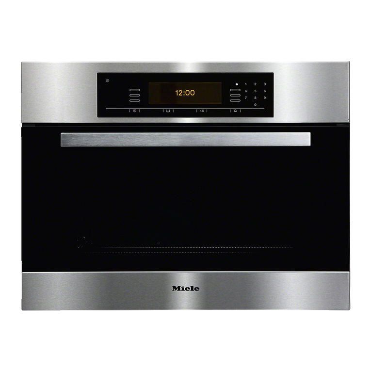
Figure 1-1: Overview of Appliance (Front View)
1 Control Panel / Display
2 Heater Element (Broiling)
3 Cavity Light
4 Temperature Probe Socket
5 Cooking Levels Supports (3)
6 Front Door Assembl
y
9

Technical Information
H4080BM Speed Oven
1.2 Overview of Controls
1 Menu Touch Pads
2 Numeric Touch Pads
3 On/Off Touch Pad
4 Display
5 Timer Touch Pad
6 Clear Touch Pad
Figure 1-2: Overview of Controls
1.3 Technical Specifications
1.3.1 Appliance Dimensions
Height 44.6cm
Width 54.7cm
Depth 54.0cm
Depth (w/ door open) 91.0cm
Table 1-1: Appliance Dimensions
1.3.2 Electrical Specifications
Voltage Requirements 120/240 VAC
Circuit Breaker
Requirements 20 amp
Electrical Connection 7.2ft cable with NEMA 14-30 Plug
Table 1-2: Electrical Specifications
10

Technical Information
H4080BM Speed Oven
1.3.3 Microwave Output Settings (Watts)
80 watts
150 watts
300 watts
450 watts
600 watts
With 208VAC supply
850 watts
80 watts
150 watts
300 watts
450 watts
600 watts
850 watts
With 240VAC supply
1000 watts
Table 1-3: Microwave Output (Watts)
11

Technical Information
H4080BM Speed Oven
1.4 Layout of Components
1 (R14) Convection Heater Element 16 (F1/2) High Temperature Cutoff
2 (M2/2) Convection Fan Motor (Magnetron) (135°C)
3 (1F1/1) High Temperature Cutoff (Broiler) 17 (G2) Magnetron
(135°C) 18 (3N1) Fuse Electronic (w/ Drop Resistor)
4 (1R30) Oven Temperature Sensor PT 1000 19 (F8) Fuse (10a)
5 (R15) Heater Broiler Element 20 (V1) Diode
6 (1F6/6) Door Safety Switches 21 (V6) Protective Diode
(2F6/6) 22 (A4) High Voltage Capacitor
(5F6/6) 23 (Y56) Release Element – Air Vent
7 (2T1) Oven Light Transformer 24 (3F6/6) Door Safety Switches
8 (1F1/2) High Temperature Cutoff (4F6/6)
(Convection) (120°C) 25 (2N1) Display Electronic (EPX)
9 (Z1) Interference Suppression Capacitor 26 (4N1) Control Electronic (EW)
10 (X3/1) Terminal Block 27 (1H3/2) Oven Light (10W Halogen)
11 (M2/1) Cooling Fan 28 (X5/8) Connector – Temperature Probe
12 (1N1) Power Electronic (EPL) 29 (3R30) Temperature Probe
13 (K1) Relay
14 (M21) Wave Distributor Motor
15 (1T1) High Voltage Transformer
Figure 1-3: Component Overview
12

Technical Information
H4080BM Speed Oven
2.0 Installation
2.1 General Information
The appliance is designed for installation into a tall cabinet in combination
with an oven, in a tall cabinet or under the countertop.
Caution!
Heating elements may be hot even though they are not glowing.
To avoid preventable damage to the appliance, follow the handling
instructions attached to the top of the appliance, as shown in Figure 2-1.
Figure 2-1: Handling Instructions Sheet (Shipped with Appliance)
13

Technical Information
H4080BM Speed Oven
2.2 Installation Procedure
1. Ensure the opening in cabinet and supports allow for proper
installation.
2. Ensure the electrical supply meets the appliance requirements (see
data tag on the appliance for details).
3. Remove all materials from the oven.
4. Place the oven near cabinet opening.
5. Ensure power supply is off.
6. Connect the oven to the electrical supply.
7. Set the oven into the cabinet niche, push it all the way in and align as
necessary.
8. Open the oven and attach the appliance to the cabinets using two
retaining screws at the sides of the frame, as shown in Figure 2-2.
9. Perform “Before Using the Appliance” procedures (Refer to Section
2.3).
Figure 2-2: Installation Retaining Screw Locations
14

Technical Information
H4080BM Speed Oven
2.3 Before Using the Appliance
Note:
The following steps must be performed after performing the Installation
Procedure (Refer to Section 2.2).
To ensure proper operation the following items should be programmed
appropriately for the customers needs:
Language
Time of Day
Time Format (12/24hr format)
Display Clock Option
1. Remove the protective film from the front of the appliance (if present).
2. Wipe the interior with a solution of warm water and liquid dishwashing
detergent.
3. Dry with a soft cloth.
4. Leave the door open until the interior is completely dry.
5. Close the oven door.
6. Wash the accessories.
Important!
New ovens may have a slight odor during the first use. To eliminate the
odor, the oven should be operated at a high temperature for 2 hours.
Before heating the oven, remove all accessories and labels from the
oven and ensure the room is well ventilated during this process.
7. Touch the "On" control.
8. Select the "Bake" function.
9. Select "Convection Bake".
10. Select "Temperature".
11. Set the temperature to 435 °F (225 °C) using the keypad.
12. Select "Duration".
13. Set the duration to two hours by entering "2", "0", "0" using the
keypad.
14. Touch the "OK" control. The oven will run for 2 hours, the remaining
time appears in the display.
15

Technical Information
H4080BM Speed Oven
3.0 Commission and Operation
A brief amount of information is provided for basic operation of the
appliance. For further details, refer to the product specific Operating
Manual (available online at Miele.com)
3.1 Functions
3.1.1 Solo Functions
Microwave: To defrost, heat and cook food in a short period of time.
Convection Bake: To bake or cook food with heated air fanned through
the interior.
Auto Roast: To roast and cook food automatically.
Broil: To broil flat cuts of food. Broiling is done with the oven door closed.
Convection Broil: To broil large cuts of meat or poultry. Broiling is done
with the oven door closed.
Defrost
3.1.2 Combination Functions
For combination of the microwave function with a traditional function
(Convection Plus, Convection Broil, Broil, Auto Roast).
3.1.3 Miscellaneous / Optional Functions
Minute Plus: To start the microwave with maximum power for 1 minute.
Master Chef Function: The Master Chef function contains an easy to
use list of preset functions of commonly cooked foods.
Favorites: Used to save frequently used programmed settings under
programmable name.
Sabbath Mode: For religious observance, the oven can be set to run for
the duration of the Sabbath.
16

Technical Information
H4080BM Speed Oven
Preselection Automatic: Feature can be used to automatically preselect
a cooking process.
Turn off Automatic: Feature can be used to turn off the cooking process.
Timer: To time any kitchen activity, etc… without cooking. Two separate
timers can be programmed.
Time of Day Display: This option displays the time of day when the
appliance is not functioning.
3.2 General Operation
3.2.1 Turning the Oven On
1. Touch the On/Off sensor to turn the oven on. The main menu
appears.
2. Select the desired menu (and then submenu – as desired) by
touching the sensor next to it.
The oven is factory set so that it starts automatically.
3.2.2 General Operation – Microwave Mode
1. Turn the oven on.
2. Select the microwave. The sub menu is shown.
3. Select the desired duration.
4. Select a microwave power setting.
5. Confirm with "OK".
6. Start the oven.
Important!
Never operate the appliance without load (i.e. food or water present in
the cooking cavity)
17

Technical Information
H4080BM Speed Oven
4.0 Description of Function
4.1 Door Safety Switches
1 1F6/6 Primary Door Safety Switch (left)
2 2F6/6 Door Safety Switch (left)
3 3F6/6 Primary Door Safety Switch (right)
4 4F6/6 Door Safety Switch (right)
5 5F6/6 Door Monitor Switch (signal to electronic)
Figure 4-1: Door Safety Switches and Monitor Switch Locations
The door safety switches are located behind the control panel near the
top left and right edges of the front door, as shown in Figure 4-1. Each
side is equipped with a primary switch (1F6/6 left and 3F6/6 right); and a
secondary switch (2F6/6 left and 4F6/6 right). Two contact pins at the
upper edge of the door activate the switches. The safety switch circuit
allows power to certain components (i.e. high voltage circuit) only if the
door is closed.
In the event a primary door safety switch fails (in the shut position) current
is directed to the electronic (3N1) and the 10amp fuse (F8) interrupts
power; preventing any further usage of the appliance.
In addition, a door monitor switch (5F6/6) is installed on the left side and
provides the electronic with the status of the position of the front door.
This switch can be checked in the service mode.
18

Technical Information
H4080BM Speed Oven
Note:
Should a safety switch require replacement, the complete assembly must
be replaced as a single component. The switches are not available as
separate components.
Important!
To ensure proper operation of the safety switches, the door must be
checked and adjusted (Refer to Section 5.9).
4.2 Cooling and Vapor Ducting
Figure 4-2: Cooling and Vapor Ducting
4.2.1 Cooling Fan (M2/1) Specifications
Voltage 120VAC, 60 Hz
RPM 2700 min
Fan (coast-down) 1200 min
Switching Temperature 149°F (65°C)
Table 4-1: Cooling Fan Specifications
19

Technical Information
H4080BM Speed Oven
4.2.2 Cooling Air Intake
Refer to Figure 4-2 – Cooling and Vapor Ducting. The cooling fan (Item 1)
draws in air through the vented openings in the appliance. The incoming
air is used to cool the appliance, the electrical components and the
surrounding cabinet on all sides.
4.2.3 Cooling Air and Vapors Path
Refer to Figure 4-2 – Cooling and Vapor Ducting. The cooling fan moves
air into the back area of the appliance (Item 2) passing over the
magnetron; and then is directed back toward the front of the appliance
and exits from the front of the appliance.
4.2.4 Air-Path During Microwave Operation
Refer to Figure 4-2 – Cooling and Vapor Ducting. The release element
(Item 4) opens, permitting a small amount of air-flow to mix with vapors in
the oven cavity. The air/vapor mix is directed through the cavity port
(Item 6) to the vent (Item 7). The air/vapor mix, again mixes with cooling
air.
Service Tip:
Should the air vent not open, air cannot exit and moisture will accumulate
in the oven cavity.
4.2.5 Air-Path During Convection, Broiler and Combination
Refer to Figure 4-2 – Cooling and Vapor Ducting. The air vent (Item 5)
remains closed. Vapors move via the cavity port (Item 6) to the vent (Item
7) and mix with cooling air.
4.2.6 Cooling Air and Vapor Exit
Cooling air and vapors are directed out of the appliance through the vent
above the air guide in the front of the appliance.
4.2.7 Cooling Fan (Coast-Down)
The cooling fan operates during the cooling phase and protects the
appliance from high temperatures and moisture. It shuts off when the
temperature in the oven cavity reaches about 158°F (70°C).
20
Other manuals for H4080BM
1
Table of contents
Other Miele Oven manuals

Miele
Miele DGC66001XL User manual

Miele
Miele DGC6700XL User manual

Miele
Miele DGC 6660 User manual

Miele
Miele H 6880 BP Instructions for use

Miele
Miele H6560BP User manual

Miele
Miele DG 6010 User manual

Miele
Miele DGC 735 Series User manual

Miele
Miele H6260BP User manual

Miele
Miele H394B Parts list manual

Miele
Miele DG 7440 User manual

Miele
Miele H 7464 BP User manual

Miele
Miele DS 30 User manual

Miele
Miele H6461B User manual

Miele
Miele H 6200 BM Instructions for use

Miele
Miele H6860BP User manual

Miele
Miele MasterChef H 4882 BP User manual

Miele
Miele H397B2 User manual

Miele
Miele H 378-1 B2 User manual

Miele
Miele H4880B Parts list manual

Miele
Miele H 4688 B User manual