Mier products DA-600 User manual

WIRELESS VEHICLE DETECTION AT ITS BEST!!!
600/605-Q12017
1) A sensor(s) detect(s) a vehicle entering
monitored area(s)
2) A control panel up to 1000 feet away receives
a signal from the sensor and triggers an alert
inside the home or business (booster antenna
increases range to 1/2-mile)
3) Add remote plug-in and/or portable chimes in
the front room, basement, upstairs, back yard,
by the pool, etc.
4) Add a timer controlled light kit to turn on
outdoor and indoor lights to warn strangers or
welcome friends
5) Activate video surveillance to record activity
and display the driveway on a monitor
6) Activate signs, gates, alarm panels or other
equipment
7) Add a repeater to send the signal another 1000’
to trigger additional alerts in out buildings, or a
booster-antenna to increase range up to 1/2-mile.
1
2 3
3
4
5
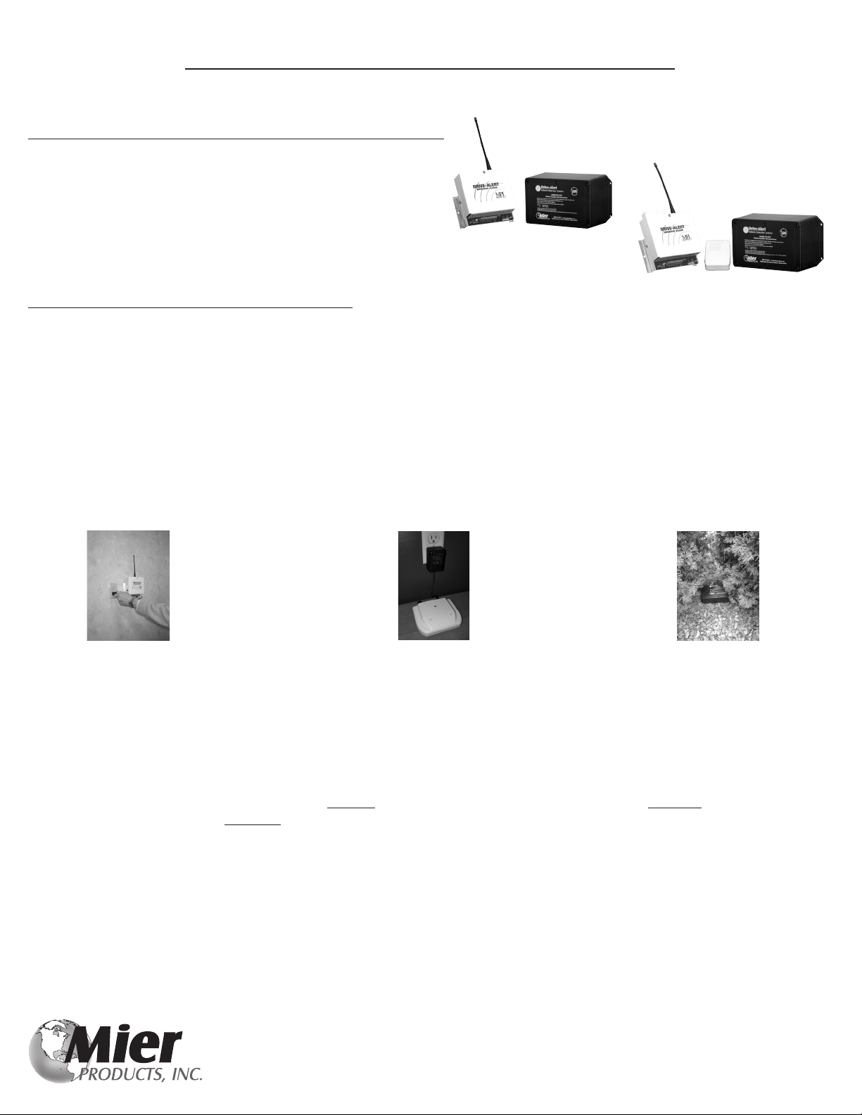
DA-600
DA-605P or DA-605B
Page(s) Content
2-4 Wireless Drive-Alert Control Panel/Receiver Installation Guide
5-7 Wireless Drive-Alert Sensor/Transmitter Installation Guide
8 Additional Installation Tips
9 Hooking Up Other Equipment to your Control Panel/Receiver
10 Options for Long Range Installations
11 Accessories: Chimes, Lights, Repeaters, Timer-Controls, Outlets, etc.
12 Supplemental Specications
13 Troubleshooting
14 Technical Support Information and Warranty
THE BASICS
MORE OPTIONS
Free Lifetime Technical Support
2
Wireless Drive-Alert Control Panel Installation Guide
The Mier Products’ Wireless Drive-Alert Detection Systems give you the benet of easy and economical wireless installation.
All Mier Wireless Vehicle Detection Systems includes 3 components:
1. Control Panel/Receiver with Additional Form C Dry Contacts
2. Sensor/Transmitter
3. Alert Sound Annunciator
* The DA-600 contains an internal piezo whistle
* The DA-605 with integrated DA-066MP wireless chime
transmitter sends a signal to DA-078 plug-in chimes
and DA-080 battery powered portable chimes
DA-600 and DA-605 Control Panel/Receivers feature:
• UL Listed 110 volt AC plug
• +24 volt DC power source for use with accessories
• Relay output available for use by accessories
• Visible POWER LED to monitor power status and LO BATT LED to monitor Transmitter batteries
• User accessible address switches to set a unique address code between the Control Panel/Receiver and the Sensor/Transmitter
• Normal reception to 1000 feet, or ½-mile if using the DA-660 Booster Antenna (see Options For Long Range Installations page)
• Use of an unlimited number of Mier Wireless Transmitters by a Control Panel/Receiver
• 100% compatibility with the Mier DA-610TO, optional DA-611TO, and optional DA-612TO Sensor/transmitters
• Compatible with Mier Accessories detailed in this manual (See Accessories Page)
EASY INSTALLATION IS OFTEN COMPLETED IN UNDER 30 MINUTES!
Plug-In the Plug-In or Place the Place the Sensor-
Control Panel Chime (DA-605 Systems) Transmitter outside
Installation Guide
FIRST, test the equipment by:
1. Plugging in the Control Panel
2. Turning the Whistle Switch ON if you have a DA-600, or plugging in DA-078 Chime if you have a DA-605P, or putting batteries
in the DA-080 if you have a DA-605B
3. Install two (2) AA batteries in the Sensor/Transmitter, observing polarity, and turn it on in the same room as the Control Panel/
Receiver. Turning on the Sensor/Transmitter will send a signal to the Control Panel/Receiver for about 15 seconds. The VALID
XMSN LED should turn on on the Control Panel/Receiver, and the audible alert should respond. If the Sensor/Transmitter is
moved after a one minute interval, the Control Panel/Receiver will be triggered again. (ex: walking while carrying the Sensor)
Once testing proves the units are communicating correctly, proceed to the following pages to learn how to:
• Properly mount the Control Panel
• Properly place the Sensor/Transmitter in the area you wish to monitor
• Properly place the chimes on a DA-605P or DA-605B system
• Test the installation
• Add accessories or long-range options
DA-600
DA-605

Free Lifetime Technical Support
3
Wireless Drive-Alert Control Panel Installation Guide
The DA-600 Drive-Alert has an internal piezo electric whistle inside the Control Panel as the audible-alert. The whistle may be
switched off if desired. The whistle and the whistle switch can be seen on the top of the DA-600 Control Panel.
DA-600 Control Panel front view top view
The DA-605 Drive-Alert’s Control Panel/Receiver board is the same as the DA-600. However, the DA-605 does not have an
internal whistle, nor a whistle switch. The advantage of the DA-605 over the DA-600 is the DA-066MP Wireless Chime Transmitter
which activates remote chimes as an alert. Any combination or quantity of DA-078 Plug-in Chimes and/or DA-080 Battery-powered
Portable Chimes may be used. Each chime is activated by a radio signal from the DA-066MP attached to the control panel. These
chimes can be used up to 100’ away from the control panel. As stated, the DA-078 plugs into any standard wall outlet. The DA-080
can be taken into the backyard, out to the pool & etc. The DA-066MP can be seen on top of the DA-605 Control Panel.
DA-605 Control Panel front view top view
The relay contacts on the terminal board are Form C dry contacts. These relay contacts may be supplied with 24 or 5 volts DC with
the addition of a jumper from the needed voltage to the C terminal. The Control Panel will operate any of Mier’s Drive-Alert
accessories listed on the “Accessories” pages of this manual. It can also be used to control other external bells, surveillance systems,
signs, gates and relays. An adjustable time control provides 2 to 12 seconds of relay closer for each vehicle detected.
CONTROL PANEL/RECEIVER INSTALLATION: (Sensor/Transmitter installation are on pages 5-7)
The Control Panel/Receiver is to be mounted indoors, 4-6 feet above ground level, where 110 volts AC power is available. To
maximize transmitter reception, the exible antenna is to be at least 12 inches from any metal pipes, power conduits, breaker boxes,
etc. Simply plug the Control Panel/Receiver into a standard wall outlet, where the signal from the Sensor/Transmitter can reach it.
For extended ½-mile range reception, or when a Control Panel must be mounted in a basement, the DA-600LR and DA-605LR
long-range systems include a special antenna “F” connector on the Control Panel/Receiver, and also inlcude a DA-660 Reception
Booster Antenna. (see the Long Range Options page)
A DA-600 Drive-Alert has a WHISTLE ON-OFF SWITCH on top of the Control Panel.
A DA-605 Drive-Alert has a remote chime with volume control. Plug in the DA-078 Remote Chime(s) or place the DA-080 Portable
Chime(s) in the area(s) of the house where an alert is desired. The DA-080 Battery Operated Portable Chime needs two (2) D batteries
which will last about 3 years. For all options and operation instructions of the chimes, see the instructions enclosed with the chimes.
The DA-078 and DA-080 chimes may be located in multiple rooms and locations, and the DA-605 can trigger an unlimited number
of chimes within 100+ feet of the DA-605 Control Panel.
Testing the communication between a DA-605 Control Panel and the Chimes is accomplished by pushing the DA-066MP Test/Call
Push-Button attached to the top of the Control Panel, and holding the button down for AT LEAST two (2) seconds, which sends a
315 MHz radio signal to trigger the two-tone (ding-dong) remote DA-078 chimes and/or DA-080 chimes. As stated, this signal will
reach at least 100 feet to the chimes. The chimes can be tested independent of the Drive-Alert Sensor/Transmitter.
The DA-066MP Chime Transmitter, and the DA-078 and DA-080 chime codes are preset. Do not change the codes.
The next page shows the electrical board and provides information and position of the Power LED,
Low Sensor Battery Warning LED, Valid Transmission LED, and Address Codes

Free Lifetime Technical Support
4
Wireless Drive-Alert Control Panel Installation Guide
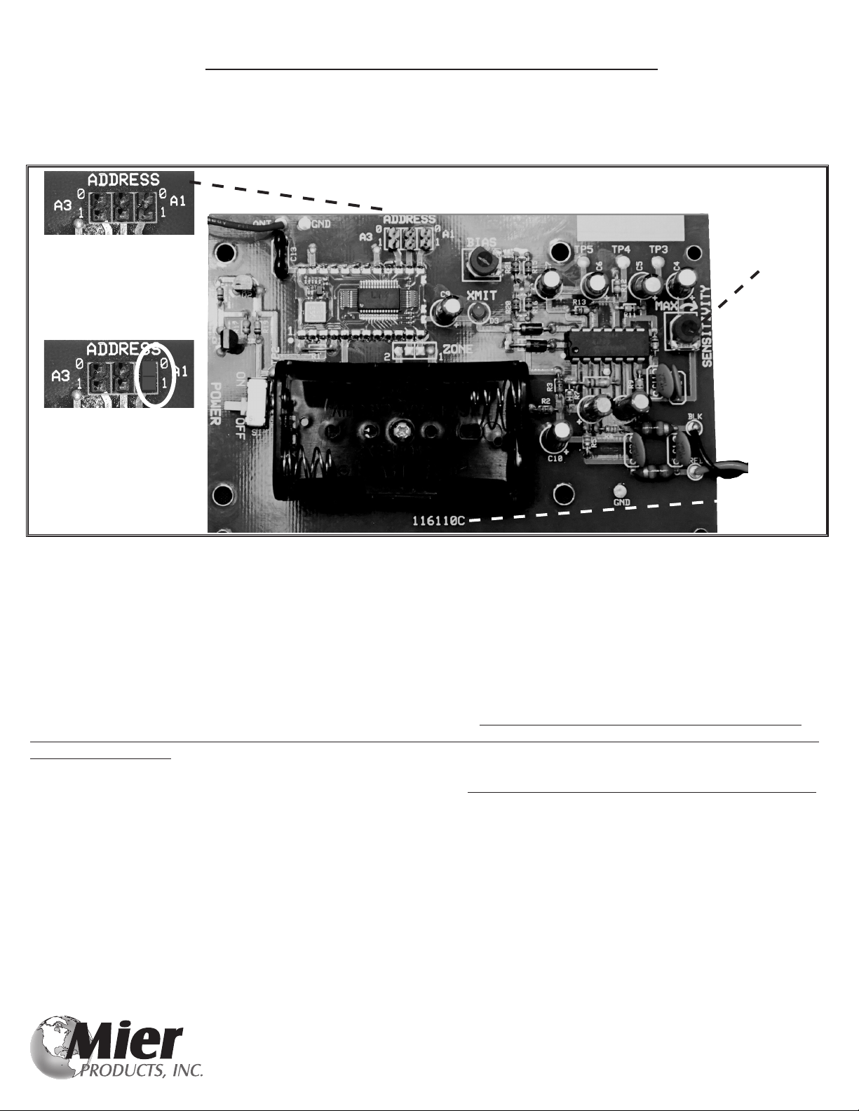
Under the Control Panel/Receiver cover you will see the electrical board (FIGURE 1).
A Power LED GREEN indicates that the power is on and that the internal 1 Amp Fuse is okay.
An Alert LED RED indicates the Sensor/Transmitter has detected a vehicle, the Sensor/Transmitter has been moved, or their is another
disturbance in the magnetic eld around the Sensor/Transmitter.
A Low Sensor Battery Warning LED YELLOW indicates when batteries are low at the Sensor/Transmitter. This LED will stay on until
the battery voltage in the Sensor/Transmitter is above 2.7 volts DC. NOTE: Before changing batteries in the Sensor/Transmitter,
unplug the Control Panel/Receiver and wait at least one minute after replacing batteries in the Sensor/Transmitter before plugging it
back in. This prevents unwanted alarms and resets the low battery detector.
The Control Panel/Receiver Address Code Switches (see SW1, SW2, SW3, SW4) must be set to match those in the Sensor/
Transmitter. These switches are preset at the factory for code 0000. They should only be changed if the Sensor/Transmitter code is
also changed. An example of when you would want to switch these codes is when two neighbors, living right next to each other,
both have Drive-Alerts: one neighbor should switch codes so both their alerts remain exclusive to their own driveways.
The Relay Time Control is preset at minimum of 2seconds of alarm time. The maximum relay closer time is 12 seconds.
The Valid Transmission LED RED is on when the Control Panel/Receiver detects a valid transmission of its address, and the Alert LED
is on when the relay is closed.
NOTE: Sensor/Alert Sensitivity Control is on the Sensor/Transmitter (see page 6), and is NOT controlled by this Control Panel.
FIGURE 1
Low Sensor/Transmitter
Battery LED
Yellow
Power LED
Green
Valid Transmission LED
Red
Alert LED
Red
Address Code Switches
Relay Timer Control
PCB version ID

Mier Products’ Wireless Drive-Alert Sensor/Transmitters detect the changes in the magnetic
eld (movement of metal) within 14’ in every direction. Therefore, they will not false-alarm from
animals, wind, rain, etc. The Transmitter electrical boards are epoxied and also encased in a
durable, weather-sealed, NEMA 4X housing for worry free weather and corrosion protection. They
are able to detect through standard building materials such as brick, stone, vinyl siding, etc. so in
many drive-up window applications they may be installed inside the wall next to the drive. They are
powered by two AA alkaline batteries, and include circuitry to transmit a low-battery condition to
Mier’s Drive-Alert Control Panel/Receivers when batteries begin to run low.
The Sensor (aka: probe or wand) portion of any of these Sensor/Transmitters should be placed
next to the drive or area to be monitored, and at least 50 feet from any road trafc to prevent false
alarms. The Sensor can be placed in any orientation, parallel or perpendicular to the drive. Any
movement of the Sensor will cause an alarm for asset protection.
Transmitting range from the Transmitter to the Control Panel/Receiver is 500 feet if placed on the
ground, up to 1000’ if mounted 2-4’ high on a metal, wood or concrete post or a convenient
building, and up to 1/2-mile if a long-range system is ordered, which includes a DA-660 reception
booster antenna. (See the Long Range Options page to learn more about the booster antenna,
adding repeaters, or adding additional DA-100 control panels)
If occasional false alarms occur, or you are not detecting some vehicles, you can try re-locating the
Sensor, or you can reduce sensor sensitivity. There is a small blue sensitivity pot on the electrical
board. Maximum sensitivity adjustment is clockwise and minimum is counter-clockwise (note
arrow direction). Reducing sensitivity would reduce detection of road trafc, but would also reduce
the detection sensitivity in the driveway. (See next page for directions)
Lightning strikes cause a large disturbance in the magnetic eld, so nearby strikes will cause an
alarm. It is also possible for electrical current variations in nearby power lines to cause an alarm.
The address codes for these Sensor/Transmitters, as well as the Control Panel/Receivers are pre-set at
the factory. However, if a unique address code is needed (e.g. interference from a neighbor’s Mier
wireless Drive-Alert) you can change the address codes making sure you do so in both the Sensor/
Transmitter AND the Control Panel/Receiver so they are different than factory spec, but still match
one another. (See next page for directions)
The Differences between Mier’s three Sensor/Transmitter Choices:
The DA-610TO Sensor/Transmitter: Both the Sensor and the Transmitter are contained in the same
NEMA 4X enclosure. (See photo at the top left) This unit is standard with complete systems.
The DA-611TO Remote-Sensor/Transmitter: The Sensor is outside the Transmitter Box, and
attached to the Transmitter by a 50’ cable (cable lengths up to 1000 feet are available). This allows
the sensor probe to be buried under or next to the driveway or area to be monitored, and the
transmitter box to be hidden up to 50’ away or placed high above ground for a better range. The
sensor should be buried 6-12 inches below ground and the cable 3-6 inches below ground. Mier
HIGHLY RECOMMENDS burying the cable in 1/2-inch PVC pipe to protect it. Try the Sensor and
Transmitter locations above ground for a week, before burying the Sensor and cable.
The DA-612TO Remote-Sensor/Transmitter: Is just like the DA-611TO, but with 2 external sensors.
DA-611TO
Detection-distance from the sensor for a standard-size modern sedan moving 5MPH
DA-610TO DA-611TO
Maximum sensitivity 14 feet 17 feet
Factory set sensitivity 13 feet 16 feet
75% sensitivity 11 feet 14 feet
50% sensitivity 9 feet 12 feet
Minimum sensitivity 7 feet 10 feet
DA-611TO installation with the Sensor
buried under the drive and the
Transmitter hidden/mounted on a
nearby tree.
DA-610TO
5
Wireless Drive-Alert Sensor Installation Guide
DA-612TO
DA-610TO installation with the Sensor/
Transmitter hidden under landscaping
next to the driveway.
Free Lifetime Technical Support
6
Wireless Drive-Alert Sensor Installation Guide
The Sensor portion of a DA-610TO, DA-611TO or DA-612TO contain the sensing and transmitting electronics and should to be
placed in the area you wish to monitor moving vehicles or assets. The detection threshold is set by a sensitivity control (See FIGURE
2: Right Hand/Middle) on the transmitter circuit board. Maximum sensitivity adjustment is Clockwise and minimum is Counter-
Clockwise. In most cases the factory sensitivity will function for the installation.
For maximum range, the Transmitter portion of the DA-610TO, DA-611TO or DA-612TO should be placed 3+ feet above ground
on a post, tree, or hung from any convenient point. The front of the Transmitter Box should also face the Control Panel/Receiver in
the home/business for best range.
The Transmitter operates on 2 - AA alkaline batteries providing 3.0 volts DC to the electronics. Please observe correct polarity
when installing. Typical battery life is 1-2 years in a residential installation. The Transmitter sends a continuous signal for about 1
minute after the power switch is turned on, and then is ready to act on Sensor inputs. When the battery voltage reaches 2.7 volts,
a low battery signal is sent to the Control Panel/Receiver in the home/business and the LO BATT LED on the Control Panel/Receiver
will be lit to indicate the batteries should be replaced soon. The receiver can be muted by turning off the whistle switch or unplug-
ging the chime to avoid annoying alarms while replacing batteries, working on or moving the Drive-Alert. After installing batteries
and conrming operation, the top cover can be put back on the enclosure with careful attention to keeping the gasket in place
and not over-tightening the screws on the cover which would cause the case to crack. Failing to do either will result in moisture
entering the enclosure. The Sensor/Transmitter can now be placed in position.
The Sensor/Transmitter Address Code Switches (see Figure 3, ADDRESS) must be set to match those in the Control Panel/Receiver.
These switches are preset at the factory for code 0000. They should only be changed if the Control Panel/Reciever code is also
changed. An example of when you would want to switch these codes is when two neighbors, living right next to each other, both
have Drive-Alerts: one neighbor should switch codes so both their Drive-Alerts remain exclusive to their own driveways.
*NOTE: The optional DA-611TO or DA-612TO are used in cases where it is impossible to securely place the Transmitter Box near
the driveway or area that needs monitoring, or when extra transmission distance is needed.
FIGURE 2
Sensitivity
Adjustment
Standard Address Pre-
set code is (000) with
no jumper
Example of changing
the address code by
placing a jumper over
a set of pins (100)
PCB Version
ID
Please contact our Tech Support Team and we will be happy to “Google™earth” your installation site, and provide you with
information on the products needed, and locations for each piece to meet your installation/application goals.
Don’t forget to check out our website for cut-sheets, installation manuals, installation examples, and information on more products!

Free LifetimeTechnical Support
7
Wireless Drive-Alert Sensor Installation Guide
1) Place the Control Panel/Receiver inside the home or ofce at least 5 feet above ground level, and plug the power cord into
an AC receptacle. The power light in the lower right hand corner of the Control Panel/Receiver will now be ON.
2) Make certain the alert annunciators are ON:
• On DA-600 models containing a piezo whistle, slide Whistle Switch on the Control Panel to the ON position
• On DA-605 models using wireless chimes, plug-in or install batteries in the wireless chimes
3) Place Sensor within 3 feet of the edge of the driveway, or the equipment/area to be monitored. The closer the better!
4) The Transmitter Box should be at least a few inches off of the ground to prevent heavy rains from ooding the unit. For
optimal detection and transmission range, mount the transmitter three (3) feet off of the ground.
5) Make sure the Sensor and Transmitter Box are at least 50 feet from streets or roads, and 40 feet from power lines.
6) Test the system using a vehicle to pass by the Sensor @ 5MPH or by swinging a steel object along the long side of the Sensor
setting off the audible alert.
Once testing is successful, choose the nal mounting locations and perform Step 6 repetitively for consistent detection and nalize
installation.
At the base of a 3-foot high for Under landscape Under a DA-ROCK1 DA-611TO
pole greater range next to the drive fake rock next to the transmitter box
drive in a tree for
greater range
Sensor/Transmitter Installation Examples
Underground OR Overhead Power or Telephone Lines
40 ft (min)
Driveway
Garage
3 ft (max)
50 ft (min)
House
1000 ft (max)
Road
Control Panel mounted indoors and at least 5 feet off the ground
Sensor
FIGURE 3

Free Lifetime Technical Support
8
Wireless Drive-Alert Installation Guide
Additional Tips for Reliable Installation:
• DO NOT mount the Control Panel/Receiver within 10 feet of a wireless modem, cell phone, or cordless phone
• DO NOT put the Control Panel/Receiver in a basement unless it is a Long-Range Control/Panel Receiver with a DA-660 Long-
Range Antenna
• DO NOT mount the Control Panel/Receiver outdoors
• DO NOT mount the Control Panel/Receiver within 12 inches of Aluminum or Steel electrical enclosures, which would cause
interference
• If you must mount the Control Panel/Receiver inside a Stucco wall, or aluminum sided wall, use a Long Range system which
includes a DA-660 Long Range Antenna which can be mounted outside the wall.
• For long-range applications, consider a Long-Range Drive-Alert System which includes a DA-660 Reception Booster Antenna
which can be mounted in an attic for additional range. Note: metal roofs will interfere with the signal, but wood/shingle is ne.
• Aluminum or Steel obstructions in the direct path of the line-of-sight from the Transmitter to the Control Panel/Receiver will
cause interference. In these cases, consider using a Long-Range Drive-Alert System and running the Reception Booster Antenna
to an area where it receives a direct signal from the Transmitter
• If there are hills in the terrain between the Transmitter Box and Control Panel/Receiver, you may need to use a DA-611TO or DA-
612TO Sensor/Transmitter and/or a Long Range Drive-Alert System
• E-Glass windows in the path of the line-of-sight between the Transmitter and Control Panel/Receiver will cause interference. In
these installations, move the Control Panel/Receiver away from the window, or consider a Long Range Drive-Alert System.
• Mount the Sensor parallel to the driveway whenever possible
• DO NOT mount the Sensor more than 3 feet from the edge of the driveway, or equipment/area to be monitored
• DO NOT mount the Sensor more than 4 feet above ground which is above the non-ferrous belt-line and might result in missed
detection
• Mount the Sensor securely: IT MUST BE STABLE AND MOTIONLESS! Any movement of the sensor will cause an alarm. Don’t
mount the Sensor on a tree, post or gate that might move in the wind.
• DO NOT mount the Sensor where it might be near underground or above ground power lines. Power surges in the sensor area
will cause false alarms.
• DO NOT bury the Transmitter Box in the ground.
• DO NOT install the Transmitter Box in an Aluminum, Copper or Steel enclosure which will result in shielding the signal
Please contact our Tech Support Team and we will be happy to “Google™earth” your installation site, and provide you with
information on the products needed, and locations for each piece to meet your installation/application goals.
Don’t forget to check out our website for cut-sheets, installation manuals, installation examples, and information on more products!
9
Wireless Drive-Alert Control Panel Terminals and Hooking Up Other Equipment
CONTROL PANEL TERMINALS:
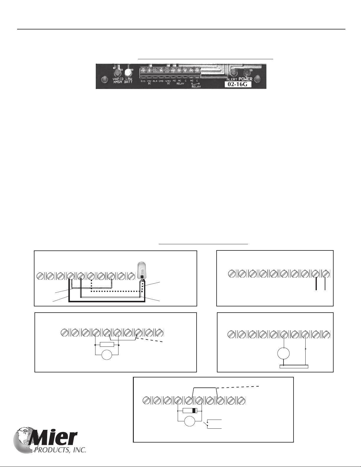
Figure 4 shows a detailed description of the contacts available. The terminal block, TB1, provides a convenient wire connection
point for external device control and test points. NOTE: All external devices must be rated at 24 VDC
FIGURE 4 shows the DA-600 and DA-605 terminals on the bottom of the Control Panel/Receiver green PCB
• Valid XMSN- Valid Transmission LED (far left) is RED and indicates if a valid signal is received from the Sensor/Transmitter
• LOW BATT - Low Battery LED is YELLOW and indicates if the batteries in the Sensor/Transmitter are running low
• SIG - Received Signal Strength (e.g. 1-1.5VDC = No Signal; 1.6-2.5VDC = Signal
• +5VDC - 5 Volt DC Logic Power @ 25mA (max)
• ALA - Alarm Signal (0-1vdc = No Alarm; 4-5 VDC = Alarm)
• GND - Unit Ground
• +24VDC - Power Supply for 24VDC @ 100 mA (.1 amp) maximum accessories
• NO - Normally Open Relay Contact
• NC - Normally Closed Relay Contact
• C - Common Relay Contact
• NO - Normally Open Relay Contact
• C - Common Relay Contact
• ALERT - Alert LED is RED and lights when the Sensor/Transmitter has detected an intrusion and is sending a signal
• POWER - Power LED is GREEN and remains on when the Control Panel/Receiver is plugged in and receiving power
NOTE: The Control Panel/Receiver will operate on 12 VDC. An auto battery with the positive (+) connected to the +24 VDC
terminal and negative (-) connected to the GND terminal will operate the Drive-Alert. Therefore, the Control Panel/Receiver can
become portable (the sensor is always portable) so the unit can be used in a vehicle or at a remote site.
***** NOTE: DO NOT PLUG THE UNIT INTO 110 VAC IF ALSO OPERATED ON BATTERY AS IT CAUSES FAILURE *****
SIG ALA +5VDC GND +24DC NO NC C NO C
Connecting Line of Sight Wireless Transmitter
such as Mier’s DA-606LK Light Kit
The Black and Red Wires attach to the last two
terminals (NO and C isolated contacts)
SIG ALA +5VDC GND +24DC NO NC C NO C
Maximum Current
Limited to 1 Ampere
Connection using dry contacts and external power
* Maximum Voltage is 24V
DO NOT apply 120VAC
BELL
External Power
SIG ALA +5VDC GND +24DC NO NC C NO C
Connecting a DA-066MP Wireless Chime Transmitter to a
DA-600 Control Panel
DA-066MP Push-Button
Wireless Chime Transmitter
Jumper
Black
White
Red
SIG ALA +5VDC GND +24DC NO NC C NO C
External 24VDC Bell with
Whistle Switch ON or OFF Capacitor
0.1 Microfarads 100 Volt (min)
Adding a capacitor extends the life
of the relay.
NOTE:
Limit of two external bells
BELL
Connection using relay contacts switching internal power
Jumper
SIG ALA +5VDC GND +24DC NO NC C NO C
NOTE: If using a DA-500 hard-wired system, and the internal piezo whistle is not wanted, move the
Whistle Switch to the OFF position and connect the jumper between +24 and the C Terminal
1N4004 DIODE
Adding the diode extends the life of the relay.
RELAY
External Relay
Hookup
24VDC
To AC operated CHIMES/ALARMS
Connection using relay contacts switching internal power
Jumper
Black Red

Free Lifetime Technical Support
10
Four Options for Long Range Drive-Alert Installations
The DA-660 Reception Booster Antenna is perfect when monitoring remote buildings or equipment:
This antenna is used to increase the standard reception distance of 1000-feet, to up to 1/2-mile from the Sensor/Transmitter to the
Control Panel/Receiver. Please keep in mind this is a FACTORY INSTALLED option, and must be ordered at the time the Drive-Alert
Control Panel/Receiver is ordered by adding an “LR” for long-range at the end of the part number. For example, a long range version
of a standard DA-605P, which would include this antenna, is a DA-605PLR.
Retro-tting an existing Drive-Alert can be done, but the system must be sent into the factory as additions need to be made to the
Control Panel/Receiver electrical board.
* 34” Long, 13” Wide, 1” High and weighs approximately 1 pound
* Frequency = 434 mHz
* Impedance = 75 Ohms
* Gain = 10.6 dB
* Type = 7 Element Yagi
The DA-REPEATER is perfect for providing additional alerts in remote buildings
This Drive-Alert Signal Repeater can an be attached to any DA-600, DA-605 or DA-500 Drive-Alert Control Panel/Receiver. It will
repeat the alert signal to other wireless Control Panel/Receivers (DA-100CP, DA-600CP, DA-605CP) up to an additonal 1000 feet
away. If a site has multiple buildings and/or locations where an alert is desired, add a DA-REPEATER to a DA-600 or DA-605 Control
Panel/Receiver, and then add DA-100CP Chimes with Volume Control (shown below) in those other buildings.
The DA-100CP Long Distance Remote Chime for adding chimes to remote buildings:
The DA-100CP is actually a self-contained Control Panel/Receiver on its own, and receives a signal from up to 1000-feet
of any of Mier’s wireless Sensor/Transmitters, OR a DA-REPEATER (shown above), and provides a pleasant tone as an
alert. It also includes volume control.
The DA-611TO and DA-612TO Sensor/Transmitters increase transmission distance:
The Sensor(s) is/are outside the Transmitter Box, and attached to the Transmitter by a 50-foot cable (cable lengths up to 1000 feet are
available). This allows the sensor probe to be buried under or next to the driveway or area to be monitored, and the transmitter box to
be hidden up to 50’ away or placed high above ground for an increased transmitting range. The sensor should be buried 6-12 inches
below ground and the cable 3-6 inches below ground. Mier HIGHLY RECOMMENDS burying the cable in 1/2-inch PVC pipe to
protect it. Try the Sensor and Transmitter locations above ground for a week, before burying the Sensor and cable.
Note: installation instructions come with these Sensor/Transmitters when ordered, or are available for download on our website.
DA-611TO DA-612TO
Please contact our Tech Support Team and we will be happy to “Google™earth” your installation site, and provide you with
information on the products needed, and locations for each piece to meet your installation/application goals.
Don’t forget to check out our website for cut-sheets, installation manuals, installation examples, and information on more products!

Free Lifetime Technical Support
11
Accessories
DA-066MP DA-078 DA-080 DA-100CP DA-REPEATER DA-606 DA-071 DA-072 DA-073 DA-ROCK1
WIRELESS DRIVE-ALERT ACCESSORIES:
• The DA-066MP Remote Chime Transmitter is used in combination with the wireless DA-078 Remote Plug-in Chime(s) and/or
the DA-080 Battery-operated Portable Chime(s) in applications where a more pleasant chime and alerts in more rooms/areas
of a home are desired. This is standard on the DA-605P. Any number and combination of plug-in chimes and portable chimes
may be used.
• The DA-100CP Long Distance Remote Chime is actually a self-contained Control Panel/Receiver that receives a signal from up
to 1000 feet of any of Mier’s wireless Sensor/Transmitters, or a DA-REPEATER, and provides a pleasant tone as an alert. It also
includes volume control.
• The DA-REPEATER can be attached to a DA-600, DA-605 or DA-500 Control Panel/Receiver and repeats the signal to other
wireless Control Panel/Receivers (DA-100CP, DA-600, DA-605) up to 1000 feet away.
• The DA-606LK Wireless Light Kit comes with a DA-606 Timer Control, one DA-071 Light-Switch, and one DA-072 Lamp
Module. Any number and combination of light-switches and lamp modules may be used. For heavy-duty applications the
DA-073 Heavy-Duty Outlet includes a top receptacle that handles up to a maximum of 1800 watts or maximum of 15 amps.
• The DA-ROCK1 is a popular accessory with all of our wireless systems, and is used to hide the DA-610 Sensor
DA-655 DA-500LKA DA-052V DA-505 DA-505W DA-050
HARD-WIRED DRIVE-ALERT ACCESSORIES:
• The Hard-Wired DA-655 Chime with Volume Control is our most popular accessory for the model DA-600 Drive-Alert in Drive-
up Window or business applications!
• The DA-500LKA is a set of Form C Dry Contacts that can be attached to the DA-600, DA-605 or DA-500 Control Panels.
• The DA-052V Whistle with Volume Control – is used with the DA-600 when a second whistle is desired (hard-wired installation)
• The Hard-Wired DA-505 Timer Control will turn on 10 amps of lights, sirens or bells from 1-45 minutes. The DA-505 unit sim-
ply plugs into a 120 VAC outlet and contains its own receptacle to provide power to lights or alarms.
• The Hard-Wired DA-505 Timer Control will turn on lights, sirens or bells from 1-45 minutes. The DA-505W is a “stand alone”
unit that gets its power from the Drive-Alert, and provides a N.O., timed, dry contact to switch a load (lights, contactors, bells,
etc) rated at 10 amps, 120 volts AC. The DA-505W is a terric intermediate interface with a “healthy” large relay within, that
may be used to control other functions such as triggering a large commercial lighting contactor, billboards, holiday lights, etc.
• The DA-050 Power Pack is a replacement power-pack/transformer for the Drive-Alerts.
If your Drive-Alert accessories do not look like these, you may have older models. Please call Mier’s free tech support line at 800-473-0213

Free Lifetime Technical Support
12
Supplemental Specications
DA-600 and DA-605 CONTROL PANEL/RECEIVER:
1. INPUT POWER: 120 VOLTS AC 50-60 HZ, 3 WATTS
2. OUTPUT POWER: 24 VOLTS DC AT 100 MILLIAMPERES (.1 AMP)
3. FREQUENCY: 433.92 MHZ FIXED SUPERHETRODYNE
4. ANTENNA: ¼ WAVE MONOPOLE FIXED BOLTED IN STEEL CASE 0 DBI GAIN
5. RECEIVER: LINX TECHNOLOGIES MODEL KH3
6. ADDRESS CODES: FOUR POSITION DIP SWITCH
7. LAMPS/LEDS: POWER, LOW BATTERY, VALID XMSN, ALARM
8. OUTPUT: PIEZO WHISTLE AND 24 VOLT RELAY
9. ALARM TIME: ADJUSTABLE 2 TO 12 SECONDS FOR EACH ALARM.
10. OPERATING TEMP: 0 DEGREE F. TO +105 DEGREE F.
11. WEIGHT: 2.5 POUNDS.
DA-066MP WIRELESS CHIME TRANSMITTER:
The DA-066MP Remote Chime Transmitter is attached to a DA-605 Control Panel and is an option on the DA-600 or DA-500. It is a 315 Mhz transmitter with ASK/
OOK encoded signal. It is activated by a relay closure on a Drive-Alert, or by pushing the button on the case. It requires 15-30 volts DC on the RED and BLACK
wires. The WHITE wire when pulled to ground will activate the transmitter.
Frequency: 315 Mhz Crystal Controlled
Power: .002 WATTS
Power Input: 15-30 Volts DC at .025 AMPS
Weight: 9 Ounces
Antenna: 1/8 Wave Quasi-Loop, -2 DBI Gain
Duty Cycle: 50% Encoder Duty Cycle at 1 Mhz
On Time: Normally 1 Second of Transmit Time
FCC ID: SGXMPIDA066
This device complies with Part 15 of the FCC Rules and Industry Canada license-exempt RSS standard(s). Operation is subject to the following two conditions:
(1) This device may not cause harmful interference
(2) This device must accept any interference received, including interference that may cause undesired operation.
Any changes not expressly authorized by Mier Products, Inc. may void the user’s authority to operate this equipment.
IC ID: 5583ADA-066MP
Cet appareil est conforme a des reglements d’industrie Canada exempts de license standard RSS (s). Son fonctionnement est soumis aux deux conditions:
(1) Ce dispositif ne doit pas causer d’interferences nuisibles
(2) Cel appareil doit accepter toute interference recue, y compris les interferences
pouvant entrainer un functionnement indesirable.
DA-610TO SENSOR/TRANSMITTER:
1. POWER REQUIREMENTS: TWO (2) SIZE AA (LR-6) BATTERIES 3.0 VOLTS DC
2. OPERATING FREQUENCY: 433.92 MHZ FIXED
3. ANTENNA: 1/4 WAVE MONOPOLE BOLTED INTO THE STEEL CASE. 0 DBI GAIN
4. TRANSMITTER OUTPUT: 2 MILLIWATTS
5. TRANSMITTER: LINX TECHNOLOGIES MODEL KH ENCODER/TRANSMITTER
6. ENCODER MODULATION: AMPLITUDE ON-OFF KEYING (OOK) AT 1200 BPS.
7. ADDRESS CODES: JUMPER PLUGS ELECTED FOR THE ENCODER
8. DATA: ONE DATA BIT ENCODED WHEN BATTERY IS LOW.
9. TRANSMITTER ON TIME: LESS THAN 5 SECONDS FOR ANY SINGLE ALARM
10. ENCLOSURE: NON-METALLIC, WEATHER SEALED ENCLOSURE HOUSES THE TRANSMITTER
11. QUIESCENT CURRENT : 60 MICROAMP
12. ACTIVE CURRENT: 3 MILLIAMP
13. BATTERY LIFE: ABOUT ONE YEAR IN RESIDENTIAL USE.
14. OPERATING TEMP: -40 DEGREES F TO + 125 DEGREES F
15. WEIGHT: THREE POUNDS
16. DETECTION OF VEHICLES: DISTANCE FROM SENSOR/TRANSMITTER UNIT FOR STANDARD SEDAN MOVING
AT 5 MPH+ IS 14 FEET (MAX), 9 FEET (MID), 7 FEET (MIN)
DA-611TO SENSOR/TRANSMITTER:
ALL SPECIFICATIONS ARE THE SAME AS THOSE LISTED FOR THE DA-610TO ABOVE, EXCEPT THE FOLLOWING:
A. THE SENSOR IS NOT INSIDE THE ENCLOSURE WITH THE TRANSMITTER. IT IS AN EXTERNAL SENSOR
ATTACHED TO THE TRANSMITTER ENCLOSURE WITH 50’ OF CABLE (SEE OPTIONS PAGE)
B. DETECTION OF VEHICLES: DISTANCE FROM SENSOR/ FOR STANDARD SEDAN MOVING AT 5 MPH+ IS 17 FEET (MAX), 12 FEET (MID), 10 FEET (MIN)
13
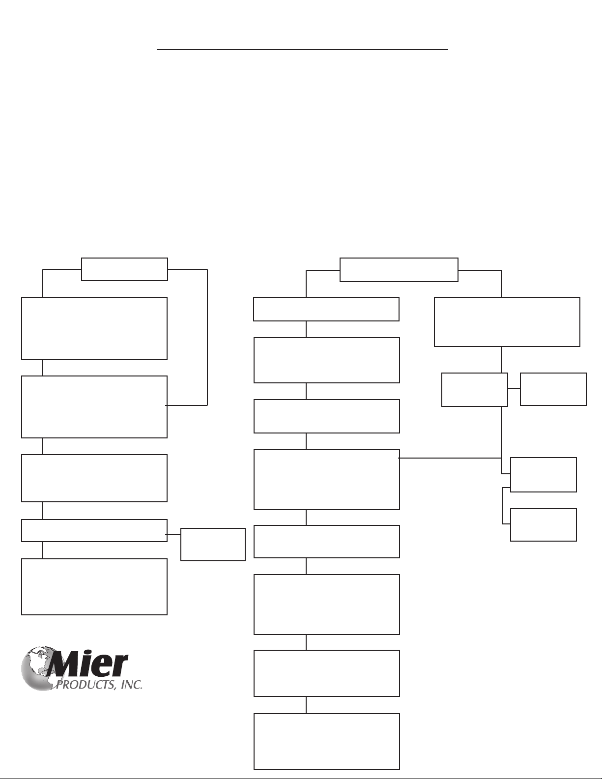
Wireless Drive-Alert Troubleshooting Trees
Step 1 - Check to make sure the Power Light is on. If not, replace the internal 1A fuse, or send to Mier Products for repair.
Step 2 - Make sure the Control Panel is mounted in an above ground area where its antenna can receive a good signal from
the Sensor/Transmitter, and make sure the Sensor/Transmitter is in a position free where it can send a signal freely.
Make sure there are no large metal objects, mirrors, aluminum siding, etc. between the Control Panel and the Sensor/
Transmitter. There is a “continuous on” or “test” switch inside the transmitter to help you test signal strength.
Step 3 - Check to make sure all address codes inside the Control Panel match the address codes in the Sensor/Transmitter
Enclosure.
Step 4 - If installing a DA-605P, make sure the address codes in the small DA-066 mounted on the side of the Control Panel
match the address codes in the Chimes.
Step 5 - If installing a DA-605P, make sure there are no large metal objects, mirrors, appliances, etc. between the Control Panel
and the Chimes
False Alarms No Detection or
Intermittent Detection
Check the sensor/transmitter
placement to make sure it is
mounted securely, and not in a
tree if a DA-610TO (this is ok if
using a DA-611TO).
Check the sensor/transmitter to
make sure it is not on the same
address code as a system at a
neighbor’s home.
Remove all accessory wires from
the terminal block.
Call Mier Products’ Free Tech
Support. They will work with you
and might recommend returning
the system to Mier Products for
diagnosis and repair.
Panel is quiet:
replace the
accessory
Check the sensor/transmitter
placement - 50’ (min) away from
the street, power/phone lines.
Move sensor or reduce
sensitivity.
ExistingNew
Accessory
Defective
OK
OK
OK
Still Not Fixed
ExistingNew
OK
Check the batteries, Power is
ON, TX_TEST is OFF/SW10
Check sensor/transmitter
sensitivity at or near MAX on
the Sensitivity Adjustment in the
lower right corner
OK
Check sensor/transmitter
and Control Panel address
codes to make sure they match
OK
Check for metal obstructions,
sensor/xmitter 5’ MAX from 10’
drive edge, vehicle does not
pass between transmitter &
receiver
OK
If using more than one sensor/
transmitter, make sure they are
more than 20’ apart
OK
Check that VALID XMSN and
ALERT LEDs come on in the
Control Panel when a detection
and transmission was to occur.
Note: listen for a Relay “click.”
OK
If using a long-range reception
antenna, check connections and
orientation (vertical and short
end pointing toward transmitter).
Call Mier Products’ Free Tech
Support. They will work with you
and might recommend returning
the system to Mier Products for
diagnosis and repair.
Still Not Fixed
Check POWER and LO BATT
LEDs on the control panel. If no
POWER LED replace the fuse.
If LO BATT replace the batteries.
No Alert or
Relay Click
Trigger sensor
by passing a
steel tool by it
Return to Mier
Products for
Repair
Flip Whistle
Switch a few
times and retry
No Alert but
Relay Clicks
Alert Sounds or
Relay Clicks
Still no Alert
Return to Mier
Products for
Repair
Free
Lifetime Technical Support
800-473-0213
www.mierproducts.com

Mier Products’ Drive-Alert Warranty
Limited Warranty for Drive-Alert Models and Accessories Manufactured by Mier Products, Inc.
Mier Products, Inc.’s Limited Warranty Program for Drive-Alert Series of Vehicle Detection Systems and Drive-Alert Accessories protects
the original owner for one year from the date of purchase against defects in original parts or workmanship. Mier Products, Inc. agrees
to repair or replace parts (Mier’s option) that are deemed defective by our Quality Control Team, without charge for parts or labor, if the
defective unit is returned prepaid to Mier Products, Inc., Kokomo, IN, within the one-year period.
Close inspection and testing, at the time of receipt by the customer, will quickly determine product quality. Thus, Mier Products, Inc.
recommends inspection of, and testing, the Drive-Alert models, direct burial cable, and accessories immediately upon receipt, before
installation or driving to an installation site, and contacting Mier Products, Inc. if quality issues arise.
NOTE: Sensors and cables that have been buried are not covered. Wireless sensors that have been sitting in ooded areas or stand-
ing water are not covered.
Mier Products, Inc. does not assume responsibility for claims or damages caused by improper installation or use of these products,
accessories, and/or products connected to or stored within them. Mier Products, Inc. does not assume responsibility for damages to
these products or their accessories due to shipping damage or damage occurring while in a customer’s warehouse and/or posses-
sion. Mier Products, Inc. does not assume responsibility for damage due to accident, faulty wiring, overload of Drive-Alert System or
Drive-Alert accessory output, or components attached to the Drive-Alert parts. Drive-Alert models and accessories must be shipped,
handled, stored, and installed with strict adherence to OEM installation instructions.
Drive-Alert accessories and parts built by other OEMs (including but not limited to chimes, lamp modules, light switches, bells, splice
kits) are covered under their respective OEM warranties.
This warranty constitutes the entire warranty with respect to Mier’s Drive-Alert Models and Accessories and IS IN LIEU OF ALL
OTHERS, EXPRESSED OR IMPLIED, INCLUDING ANY WARRANTY OR MERCHANTABILITY AND WARRANTY OF FITNESS FOR
A PARTICULAR PURPOSE AND IN NO EVENT IS MIER PRODUCTS, INC., OR IT’S DISTRIBUTOR, DEALER, OR OEM PARTNERS,
RESPONSIBLE FOR ANY CONSEQUENTIAL DAMAGES OF ANY NATURE WHATSOEVER.
Any warranty OR sales questions should be directed to Mier Products at 800-473-0213, or via e-mail to [email protected]
Any repair work not covered by this Warranty is available for a nominal charge.
Products which customers wish to return for reasons other than Warranty must rst call Mier Products, Inc. to receive a Return Material
Authorization Number (RMA#). Returns are subject to a 15% re-stocking fee as well as return shipping. NOTE: Special Order
products, such as Mier’s Temperature Controlled Enclosure line, are non-cancellable and non-returnable.
14
Mier Products’ Drive-Alert Technical Support
Mier Products, Inc. provides free telephone and email lifetime technical support for all of our Drive-Alert vehicle
detection systems. Call us between the hours of 8:00 am and 5:00 pm EST, send an email, or download our Cut-Sheets, Instruction
Manuals, or FAQs from our website.
800-473-0213 ~ info@mierproducts.com ~ www.mierproducts.com
Wireless Vehicle Detection | Buried Sensor Systems | Driveway Alarms | Drive-Up Window Detection | Instrument Boxes | DVR & CPU Lockboxes | Flush-Mount
Cabinets | NEMA Outdoor Enclosures | NEMA Temperature Controlled Enclosures | NEMA Rack Enclosures | Rack Shelves and Drawers | NEMA/UL Non-
Metallic Enclosures | Power Supply Boxes | Siren/Speaker Cabinets | Bell Boxes | Battery Cabinets | Transformer Enclosures | Custom Enclosures and
Fabrication | Custom Graphic Screening and Colors

This manual suits for next models
6
Other Mier products Security Sensor manuals


