Mier products DA-611TO User manual
DA-100 Drive-Alert
now with new Zone Control and Alert Tone Selection features
THE BASICS
A sensor detects any vehicles entering a monitored area
A control panel receives a signal from the sensor and triggers an
internal chime with volume control
The DA-100 allows you to monitor up to three separate areas with
one receiver! You may monitor multiple areas, lanes, driveways by
adding additional DA-610TO or DA-611TO sensor/transmitters.
You may also add alert chimes to multiple buildings by installing
DA-100CP control panels in those areas.
Use these systems in conjunction with Mier’s other wireless Drive-
Alert systems such as DA-600s or DA-605s.
MORE OPTIONS
PN: MP0105326
DA-100
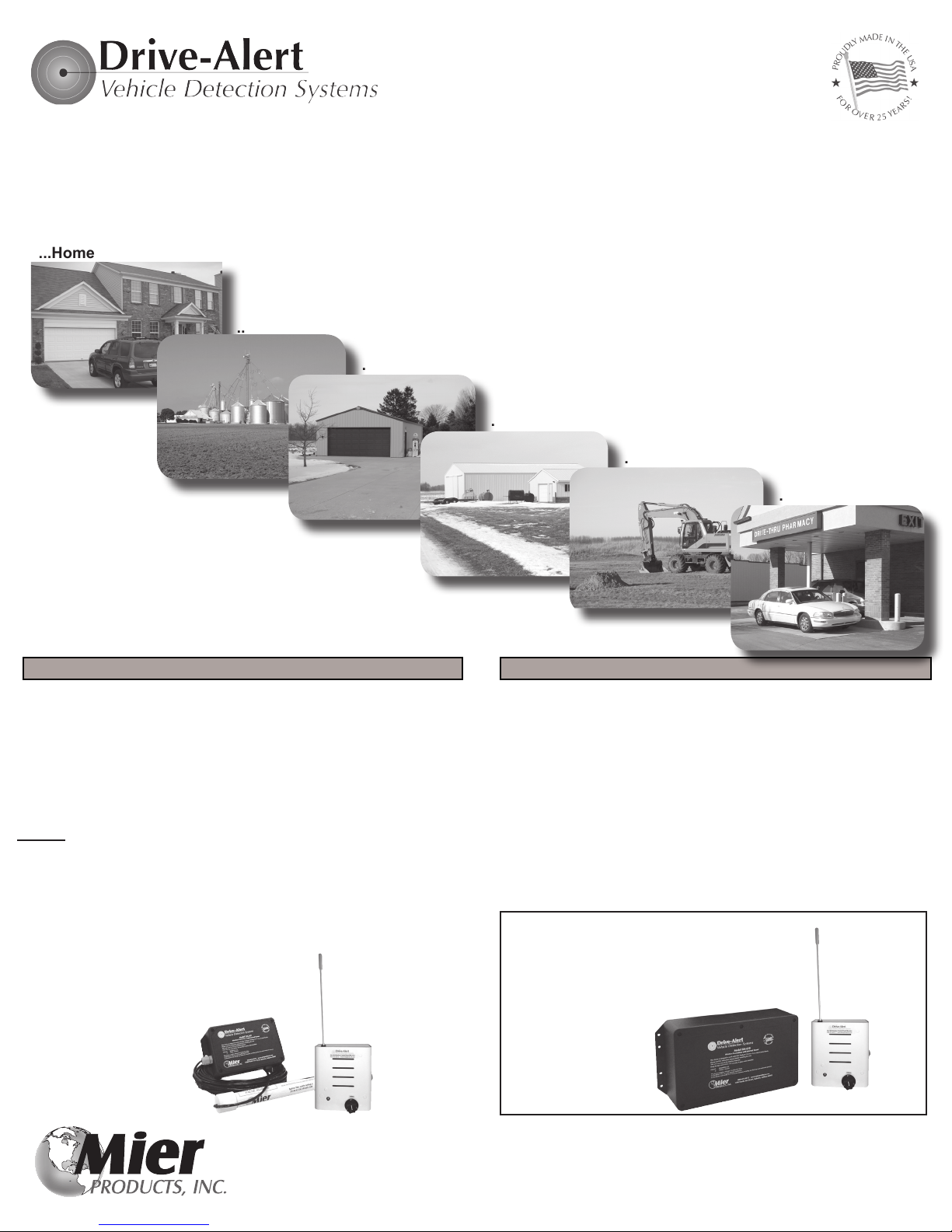
The DA-100 is a COMPLETE KIT which includes:
• One DA-100CP Control Panel receiver with built-in chime, volume
control, and three choices of chimes
• One DA-611TO Sensor/Transmitter with 50 feet of cable
• Zoning Control to monitor up to three dierent areas and provides a
dierent tone for each. (NOTE: additional Sensor/Transmitters are
needed for each additional area to monitor)
Optional set-up shown here includes:
• One DA-100CP Control Panel receiver
• One DA-610TO Sensor/Transmitter with the
sensor inside the transmitter box
Detect vehicles and monitor areas and assets at your...
...Home
...Farm
...Workshop
...Remote Buildings
...Equipment
...Drive-Up Window
DA-611TO
Sensor/Transmitter
It also detects assets moving such as trailers, RVs, tractors, boats, or
anything a sensor is attached to.
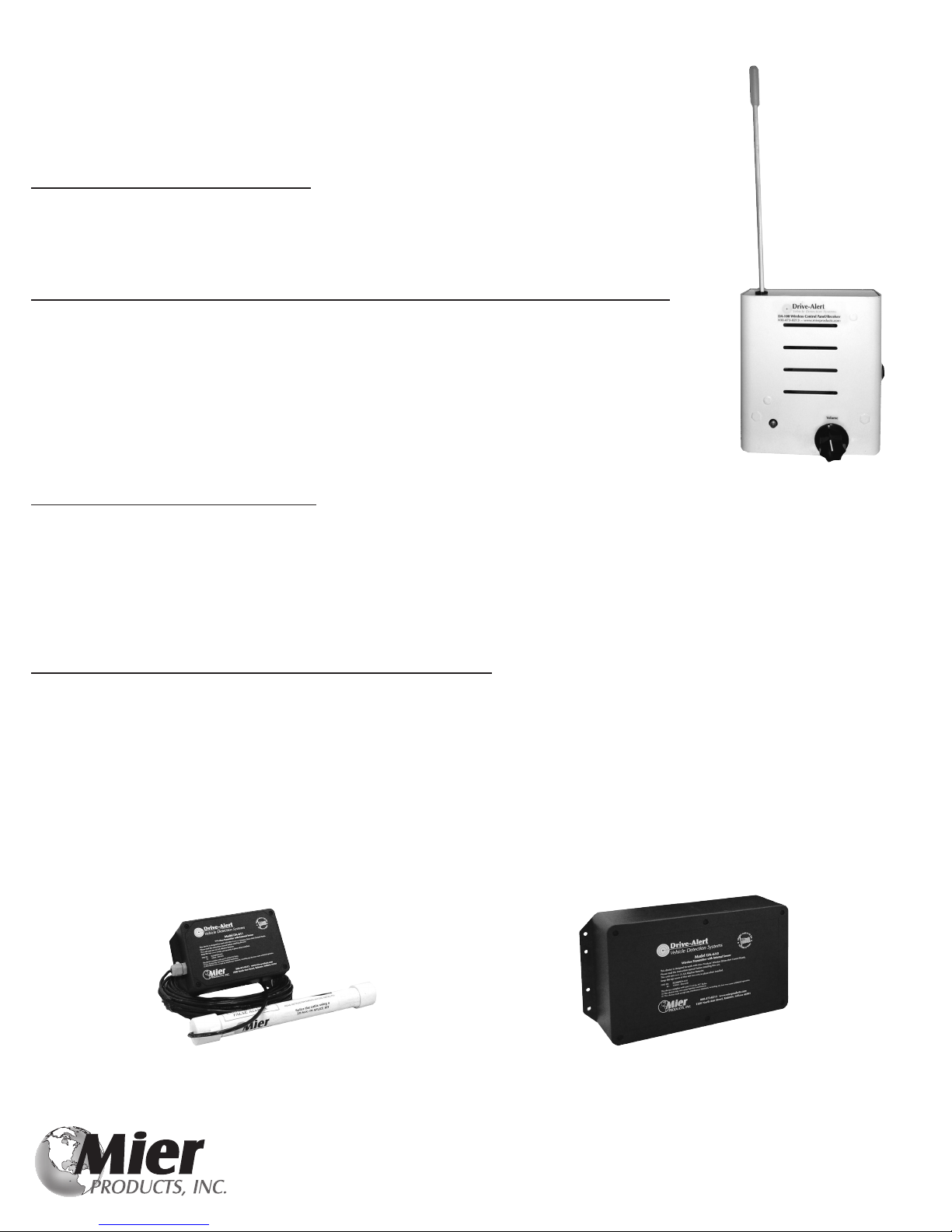
DA-100CP
Control Panel
DA-610TO
Sensor/Transmitter
DA-100CP
Control Panel
DA-100 Installation Manual page 2
Mier Products’ DA-100 Drive-Alert gives you easy and economical wireless installation.
The DA-100CP Control Panel Includes:
• Wireless receiver board inside a durable metal enclosure
• Beginning mid-2018, an Alert Chime Select Switch allows users to choose from three (3) dierent chime alerts
• Internal chimes with on/o switch and full-range volume control knob
The DA-611TO Sensor/Transmitter and optional DA-610TO Sensor/Transmitter features:
• The DA-611TO comes with the sensor outside of the transmitter enclosure attached with 50’ of cable.
Longer lengths of cable are available. Burying the cable and sensor within a PVC pipe is recommended to protect and
prolong cable and sensor life.
• The optional DA-610TO includes the sensor inside a larger transmitter enclosure (no cable).
• Mier’s sensors detect any disturbance in the magnetic eld (moving vehicles) and not people or animals.
The sensors are even able to detect through walls made of standard building materials.
• A wireless transmitter board is within the NEMA 4X outdoor enclosure, and is powered with two (2) 1.5 volt AA (LR6)
Alkaline batteries. When the sensor is tripped, it sends a signal to the control panel.
NOTE: Typical battery life at a residential installation is over 3 years, and over 1 year at a drive-up window application.
All Mier Wireless Vehicle Detection Systems feature:
• UL Listed 24 volt DC wall transformer (115VAC)
• Normal reception over 1000 feet line-of-sight
• Use of an unlimited number of Mier’s Wireless Sensor/Transmitters or Mier Control Panel/Receivers
• 100% compatibility with any of Mier’s Wireless Sensor/Transmitters and Wireless Control Panels
• By selecting the ZONING FEATURE (see page 3, the three separate tones will alert for three (3) dierent driveways or areas
Before Installation, perform the following BENCH_TEST steps:
1. Apply power to the DA-100PLUS Control Panel/Receiver. Turn the volume switch up at least halfway, and check that the GREEN Power LED is on.
2. Remove the cover from the DA-611TO or DA-610TO. DO NOT wipe o the silicone grease which adds an additional layer of environmental protection.
3. Install two (2) 1.5 volt AA (LR6) Alkaline batteries, observing proper polarity.
4. Turn on the DA-611TO or DA-610TO power switch. The RED Transmit LED should come on and the DA-100CP should chime.
NOTE: Some early models of the DA-611TO may not have a power switch or red LED. These units become active as soon as the batteries are installed.
5. Reinstall the cover being careful not to over tighten the screws which could crack the cover.
6. Turn o the DA-100 Control Panel after conrming that it chimed in Step 4.
See next page for EASY Installation Instructions...
DA-100CP
Control Panel/
Receiver with
Alert Chimes
DA-610TO
Sensor/Transmitter with internal sensor
DA-611TO
Sensor/Transmitter with external sensor

DA-100 Installation Manual page 3
EASY Installation is often completed in under 30 minutes!
1. AFTER BENCH TESTS FROM PAGE 2 ARE COMPLETED: install the DA-611TO Sensor/Transmitter, or the entire DA-610TO, within 3 feet of the drive
or area you wish to monitor, parallel to the trac for best performance. (See Figure 1 and Examples below)
2. The sensor should be at least 30 feet from power lines and 40-50 feet away from street trac if possible. Call our free Tech Support if it is a drive-up
window or short drive installation. (See Figure 1 below)
3. The sensors detect up to 14’ in every direction if sensitivity is set at maximum.
4. The DA-611TO sensor and cable may be buried 2-12 inches underground (AFTER On-Site testing above ground for a few days). Excess cable may be
coiled and/or buried. The Transmitter box should be mounted at least 5 feet above ground.
5. If using a DA-610TO, and it is mounted on the ground, expect a 500 foot transmission range. If a DA-610 is mounted 3-5 feet high, then you may expect
transmission range of over 1000 feet. A DA-610TO MUST be mounted securely, as it will signal an alarm whenever it is moved. For example, mounted on a
tree that sways in the wind will cause false alarms.
6. Set up the DA-100CP Control Panel receiver 5+ feet above ground inside the home/building, turn on the volume at least halfway, and make certain the
green LED power light is on. (See Figure 1 below)
7. Test the installation using a vehicle traveling at least 5 MPH. Once satisfactory performance is achieved, then permanently mount all equipment.
Easy Installation continued on page 4...
Free Lifetime Technical Support
At the base of a pole 3-5foot high for greater Under landscape next to Under a DA-ROCK1 fake DA-611TO transmitter
range the drive rock next to the drive box in a sturdy tree for
greater range
Sensor/Transmitter Installation Examples
Underground OR Overhead Power or Telephone Lines
40 ft (min)
Driveway
Garage
3 ft (max)
50 ft (min)
House
1000 ft (max) Road
DA-100CP Control Panel mounted indoors and at least 5 feet o the ground
Sensor
FIGURE 1 - SINGLE ZONE, BASIC SET-UP EXAMPLE

DA-100 Installation Manual page 4
EASY Installation continued...
8. Changing Chime Selection: To select an alert chime sound in the Control Panel manual mode, move the tone-select switch to one of the three available
tones. No. 1 position is a “ding-dong”, No. 2 position is a “ding-ding-ding” and the No. 3 position is a “dong-ding-dong” alert. (See Figure 2)
9. Zoning Set-Up: To utilize the Zone features, remove the two (2) screws from the chassis, pull o the cover, and locate the JP3 Jumper-Header on the
Zoning Pin, and pull the Jumper-Header o (see #9 on Figure 3 below). Then replace the cover on the enclosure. In the Zone Mode the receiver will
provide a dierent tone for up to (3) dierent transmitters monitoring (3) dierent driveways. Additional DA-611TO or DA-610TO Sensor/Transmitters will be
needed for each additional zone to be monitored (see Figure 4).NOTE: The tone-select switch is disabled in the zone mode: the tone select is automatic.
10. Equipment Addressing: The Control Panel AND the Sensor/Transmitter are already set for the default address mode from the factory, with NO Jumper-
Headers on the address pins. IN THE RARE CASE of a neighbor’s system interfering with your system, use the Jumper-Headers to select dierent
address pins for your system. Make certain they are the same in BOTH your Control Panel AND Sensor/Transmitter. You can place a Jumper-Header on
one set of pins, or the other, or on both sets of pins depending on how many other system addresses are nearby. (see #10 on Figure 3 below)
Free Lifetime Technical Support
FIGURE 3
Electrical Board inside the DA-100CP
10.) Photo of Default addressing above
shows NO Jumper-Header on the Address
pins. Change address by adding a Jumper-
Header on either set of address pins.
9.) Photo of Default Single Zone shows a
Jumper-Header on the Zoning pin. Activate
Zoning Mode by removing this Jumper-
Header from the Zoning pin.
FIGURE 2
Alert Chime Tone Selection Switch
AA
A
B
B
B
B
FIGURE 4
Example of a farm with Zoning activated
A) Three (3) zones monitored with sensor/transmitters. These can be either DA-611TOs or DA-610TOs.
B) Four DA-100CP Control Panel/Receivers with alerts placed in the home, in the work shed, and in two barns.
In this installation, the owners are alerted to vehicles
approaching in any of the three driveways by the sensors placed
in areas marked “A”, with dierent alert chime tones for each so
the owners know exactly which drive the vehicle is in, and those
alerts are communicated in four dierent buildings where control
panels are mounted marked “B”.
Mier Products oers the FREE service of using satellite imaging
like the photo shown, and talking with the installer to determine
which equipment needs to be installed in each location to satisfy
the customer’s need. Just give us a call!
Jumper-Header shown here:
This manual suits for next models
3
Table of contents
Other Mier products Security System manuals

Popular Security System manuals by other brands


Directed Electronics
Directed Electronics 29402 user manual

Audiovox
Audiovox Prestige MA200C Installation guide and owner's manual

Pima
Pima HUNTER-PRO 896 user guide

GRASS VALLEY
GRASS VALLEY KALEIDO-MX quick start guide

APEC CCTV
APEC CCTV ADR-5008 user manual

Videofied
Videofied XL 3.1 Hand Programming Manual


