Mikasa MVC-40H User manual

FOR MORE INFORMATION
CONTACT US ON 1300 353 986 OR VISIT flextool.com.au EXCLUSIVE TO
Version 1.0 (May 2022)
SERVICE MANUAL
MIKASA FORWARD PLATE COMPACTOR
MVC-40H, MVC-F60H, MVC-F80H,
MVC-T90H, MVC-T100D

PLATECOMPACTOR
MVC
SERVICE MANUAL

Table of contents
1
1
1
2
2
2
2
2
3
3
5
7
8
9
9
9
11
11
Work Site
Clothes And Protective
Cautions During Refuelinglothes And Protective
Prevention Of Burn And The Accident Of Getting Caught
Tools And Equipment
Use Of Genuine Parts And Appropriate Oil And V-belt
Tightening Torque Of Bolts And Nuts
Disposal Of Waste Material
Inspection And Maintenance Schedule Table
Opening Engine Oil
1.
3.
5.
6.
7.
8.
9.
8.1
8.2
9
10
Changing Air Cleaner
Checking/Changing V-belt and Clutch
8.3
8.4
10
10
Inspection and Change of Vibrator Oil
Inspection and Change of Engine Bolt
8.5
8.6
12
Engine
Main Body
9.1
9.2
8
8
Disassemble
Assemble
7.1
7.2
3.1
3.2
3.3
3.4
3.5
3.6
3.7
3.8
INTRODUCTION ......................................................................................
CAUTIONS FOR MAINTENANCE TO SECURE SAFETY .......................
1
2. WARNING SIGNS ....................................................................................
INSPECTION BEFORE OPERATION ......................................................
4
4. TOOL ........................................................................................................
CAUTIONS BEFORE MAINTENANCE WORK ........................................
DISASSEMBLY AND ASSEMBLY OF VIBRATOR ..................................
REGULAR CHECK AND ADJUSTMENT .................................................
TROUBLESHOOTING .............................................................................

1
1.INTRODUCTION
For correct operation, maintenance and service of Plate Compactor, please read the separate operation manual before
your work for your safe work.
For the handling of engine, please read the separate engine operation manual and maintenance/service manual.
This service manual explains the maintenance standard and how to disassemble and assemble for Plate Compactor.
Please read this service manual for a better understanding of the maintenance standard, the structure and function of
each part.
To improve the performance and quality of this machine, the change might be made in this machine without notice. If
you have any questions, please contact with our distributor. For parts list, Mikasa WEB parts list is available at our
homepage (http://www.mikasas.com/).
●
●
●
●
2.WARNING SIGNS
The triangle shaped marks used in this manual and on the decals stuck on the main body
indicate common hazards. Be sure to read and observe the cautions described.
Warning labels indicating hazards to humans and to equipment.
DANGER
!
WARNING
!
CAUTION
!
CAUTION
!
Denotes an extreme hazard. It calls attention to a procedure, practice,
condition or the like, which, if not correctly performed or adhered to, is
likely to result in serious injury or death.
Denotes a hazard. It calls attention to a procedure, practice, condition
or the like, which, if not correctly performed or adhered to, could
result in serious injury or death.
Denotes a hazard. It calls attention to a procedure, practice, condition
or the like, which, if not correctly performed or adhered to, could
result in injury to people and may damage or destroy the product.
Failure to follow the instructions may result in damage to property.
!
(without at )
3.CAUTIONS FOR MAINTENANCE TO SECURE SAFETY
Do not work indoor or inside a tunnel where ventilation is poor. The emission from the
engine contains toxic gas such as carbon monoxide, and it is very dangerous if this
toxic gas and dust are inhaled. Also, to improve ventilation, please keep a proper
distance between this machine and a building when operating the machine.
Maintenance should be done in a place with a flat and hard surface to keep the
machine stable. Also, do maintenance at sufficient work space.
Before maintenance work, clean the floor. Oil on the floor, in particular, becomes the
cause of falling accident.
For maintenance work, have sufficient lighting in the work site. A portable lamp used to
illuminate the work area has to be protected by wire. In case if the lamp is broken, fuel
and oil might ignite.
To prepare for an accident, please have emergency medical supplies and fire
extinguisher ready at an easily accessible area.
3.1 Work Site
●
●
●
●
●
CAUTION
!
DANGER
!

2
To work safely, wear work clothes of appropriate size, and use suitable protective gear
such as helmet and safety shoes. The work clothes that do not fit the body size might
result in unpredicted injury because the clothes easily get caught by rotating part of the
machine.
When adding fuel
If fuel is filled to the top, it might overflow, and is dangerous.
After refueling, securely tighten the tank cap.
Start your work after the machine temperature drops. Especially, the muffler gets very
hot, and it will pose a danger of burn accident. Also, engine and engine oil as well as
vibrator become hot. Be careful not to get a burn.
If maintenance work is started with the engine running, injury might occur because you
might get caught by the rotating part such as pulley and V-belt. Always stop the engine
before maintenance.
When lifting the machine body and the engine, always use a crane. When lifting the
machine and the engine, follow the cautions listed below. If the machine or the engine
is dropped, a serious accident might occur.
To operate a crane, a crane handling qualification is required. Have someone qualified
to handle and operate a crane do this work.
Before lifting, check the parts (especially, hook and anti-vibration rubber) of this
machine for damage and loosening/lack of bolts to secure safety.
Before lifting, stop the engine and shut the fuel cock.
Use sufficiently strong wire rope.
For lifting, use only the lifting hook. Do not use other part for lifting.
Never allow anyone or any animal come under the lifted machine.
For safety, do not lift to the height more than necessary.
Use an appropriate tool. If the tool that is not suitable for the part is used, not only the
damage on the part, but also unpredicted accident might occur.
Always use genuine parts.
If inappropriate parts are used, not only it will shorten the machine life, but it might lead
to unpredicted accident.
Always refuel in the well ventilated area.
Always refuel after the engine stopped and cooled sufficiently.
Select a flat surface location away from flammable material and Do not overfill
the tank. If spilled fuel, wipe it off well.
Never put fire near the refueling area. (Never refuel while smoking.)
3.2 Clothes And Protective
3.3 Cautions During Refuelinglothes And Protective
3.4 Prevention Of Burn And The Accident Of Getting Caught
●
●
●
●
●
●
●
●
●
●
●
●
●
●
●
●
WARNING
!
3.5 Tools And Equipment
WARNING
!
CAUTION
!
CAUTION
!
○
○
○
○
3.6 Use Of Genuine Parts And Appropriate Oil And V-belt
CAUTION
!

3
Tighten bolts and nuts with the tightening torque specified in this maintenance manual.
Over tightening torque and lack of tightening torque not only affect the machine life, but
also might occur unexpected accident.
Unnecessary engine oil and fuel should be kept in a container. Never dump it on the
ground or pour into the sewage system such as side ditch.
For disposal of unnecessary engine oil and fuel, follow the law and other regulations.
●
●
●
WARNING
!
3.8 Disposal Of Waste Material
CAUTION
!
3.7 Tightening Torque Of Bolts And Nuts

4.TOOLS
1. Wrench
Offset wrench/Socket wrench/Adjustable wrench
2. Hexagonal wrench 3. Plier
4. External snap ring plier/Internal snap ring plier(bent type can be also used)
6. Metal and plastic hammers 7. Pulley puller
8. Screw lock agent
(Locktite 243, 272)
9. Liquid gasket
+ー
5. Screwdriver, flat and cross
10. Hour/Tacho Meter
(PULSE ENGINE TACHOMETER PET-2000DX)
Parts No. 9800-10130
11. Torch burner
4

Temperature
Morethan25℃
10〜25℃
10〜0℃
Lessthan0℃
Useoil
SAE#30
SAE#30,#20
SAE#20
SAE#10
5.INSPECTION BEFORE OPERATION
Set the machine on a level surface, then
remove the oil gauge of the vibrator. Check
the oil gauge to see if the oil is at the speci-
fied level. Use engine oil SAE10W-30 as
lubrication oil.
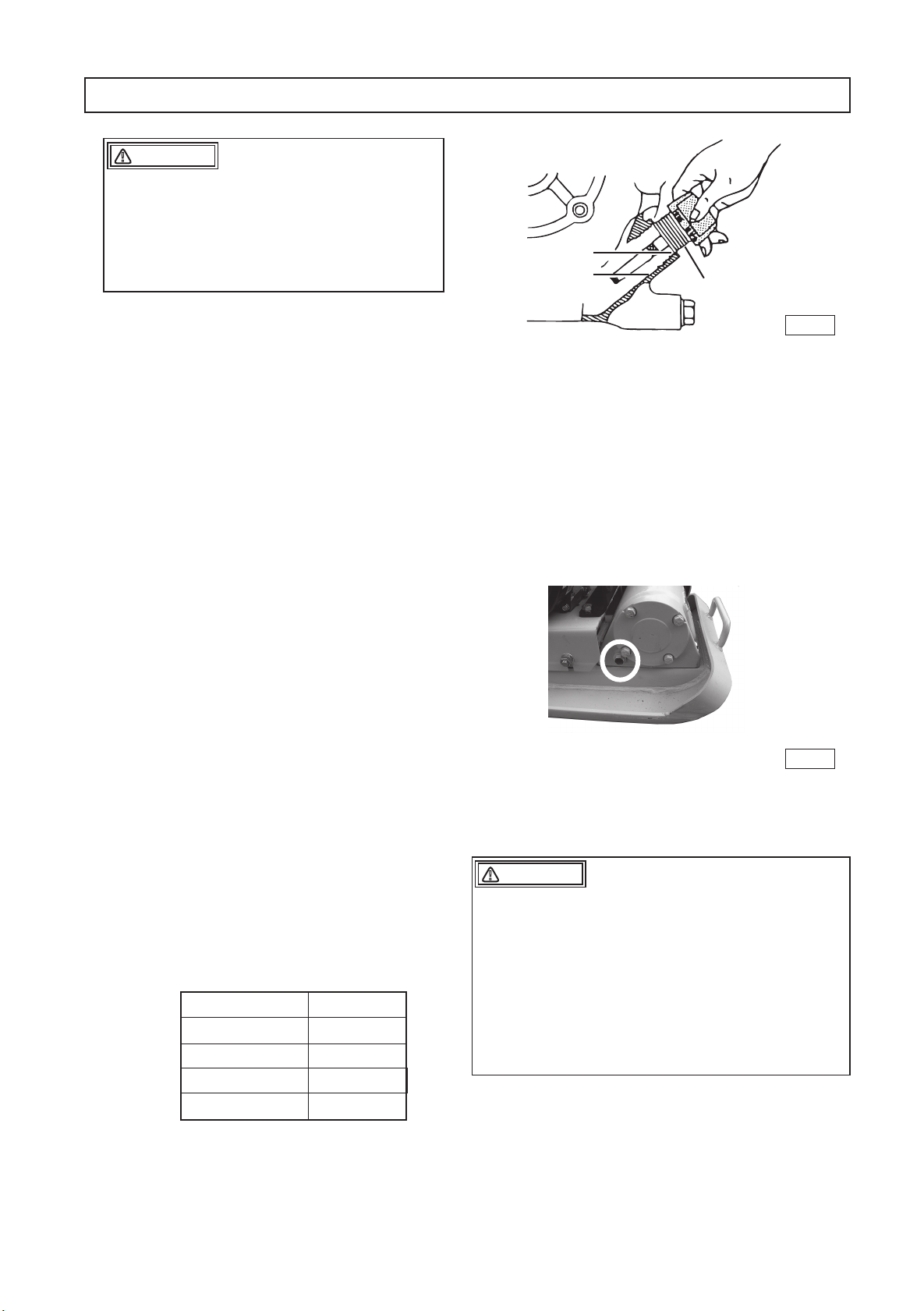
Remove the drain plug in Vibrator Assembly
and check the oil level. Make sure the oil
quantity is set at level of plug hole for check-
ing. Every month or every 200 hours of op-
eration, replace the oil.
A regular grade gasoline should be used in
the engine. When filling the fuel tank, make
sure the fuel filter is used.
Never refuel this machine while leaving the
engine running. There is danger of fire.
Never smoke, or put other flames close to
this machine while refueling. Serious haz-
ards such as burns and fire may result.
Choose a place free from flammable sub-
stances for refueling. Be careful not to spill
fuel. In case fuel should be spilled, wipe off
the spilled fuel completely.
Clean each part of the machine well to main-
tain dirt and dust-free condition. Pay special
attention to the soil adhered to the bottom of
the vibrating plate, engine cooling air inlet,
and the carburetor and air cleaner area to
keep those parts clean.
Check each part for any looseness of bolts.
Vibration causes bolts & nuts to loosen,
which might result in unexpected accident or
malfunction.
Inspect the guard hook, belt cover and an-
ti-vibration rubber, as well as to check the
function of speed adjustment wire and
speed adjusting lever.
Check V-belt tension. The belt should have
about 10 – 15mm of flexibility when pushed
strongly with a finger at the mid-point be-
tween the axes. If V-belt is loosened, power
is not transmitted well, which reduces com-
pacting force and shortens the life of V-belt.
In addition, the generated compaction force
will lead to irregular vibrations when the
engine revolutions are increased, and may
result in a machine failure.
Set the engine on a level surface to check
the oil level. If the oil level is low, add oil.
Use the following engine oil.
1.
2.
3.
4.
5.
6.
7.
●
●
●
Conduct inspection while the engine is
stopped.If you get caught in the rotating
parts, you may suffer serious damage.
Conduct inspection after making this ma-
chine level and checking that the body
does not move.
DANGER
!
Quality
:
Gasoline engine oil, Grade SE or above
Viscosity: SAE No. 30 at 20°C and above (summer)
SAE10W-30
Fig. 1
Upper level
Lower level
(refil needed) Oil gauge
DANGER
!
5
Fig. 2
※ The illustration is shown for model, "MVC-F60"

6
Pour water into the water tank for sprinkling
work.
Note:
Pour water only. If you should put liquids
other than water, the resin, tank cap seal,
etc. may deteriorate or swell, leading to
leakage or damage.
The water tank can be removed by pulling it
upward. When mounting the water tank
again, insert the hook into the groove of the
water tank securely. The amount of sprin-
kling water can be adjusted by the cock.
8.

7
Disassembly and assembly of this machine, with inspection and change of vibrator oil included,
should be done on a horizontal surface area. Before disassembly and assembly, understand well
the normal assembly condition so that you will not make assembly error.
If oil seal, gasket, packing, O-ring or lock washer is disassembled, replace it with a new one each
time.
The contact surface between vibrating case and vibrator cover should be sealed with Packing or
O-ring. (Clean the contact surface and be careful about O-ring position when assembling.)
Apply Liquid Gasket (Three bond 1215 or equivalent) on the each side of packing of Case Cover.
When tightening bolts and nuts, tighten them according to the specified standard torque and
applying the screw lock agent (Loctite, etc.). For bolts and nuts with no specification, refer to the
“Tightening torque list”. (When applying screw lock agent, degrease and clean the screw part with
the brake cleaner, etc.)
Note) The bolts used on this machine are all of the right hand thread.
When disassembling and assembling, work in the maintenance shop without dirt and dust.
When the bolts applied the screw lock agent (Loctite, etc.) are difficult to loosen, they loosen
easily by heating them with a torch burner. Then, replace the heated bolt with a new one. It
should be a specified high tension bolt (genuine parts).
Use correct tools correctly.
1.
2.
3.
4.
5
.
6.
7.
6.CAUTIONS BEFORE MAINTENANCE WORK
Tightening torque list
To change the unit to kgf
・
cm, convert with 1 N
・
m = 10.197 kgf
・
cm.
(unit: kgf-cm, 1kgf-cm=9.80665N-cm)
6mm 8mm 10mm 12mm 14mm 16mm 18mm 20mm
4T(SS41) 70 150 300 500 750 1,100 1,400 2,000
6-8T(S45C) 100 250 500 800 1,300 2,000 2,700 3,800
11T(SCM3) 150 400 800 1,200 2,000 2,900 4,200 5,600
When the mating material is aluminum. 100 300~350 650~700
Thread diameter
Material
(Bolts used on the machine are all right-hand thread.)
400
750
400
400
Specific points Item
Tightening torque
Drain bolt for Vibrator Plug
Outside of Shock Absorber
Inside of Shock Absorber
M10 Bolts
M10 Nuts (F60H/F70H/F80H)
M10 Nuts
Tightening torque at specific points (kg-cm)
Application point Type of Screw lock agent
To assemble vibrator on vibrating plate Locktite272
To assemble case cover
Locktite243
To assemble pulley to vibrator
To assemble Clutch AY to Engine
To assemble shock absorber between
engine base and vibrating plate
Screw lock agent application point

8
1.
2.
3.
4.
5.
6.
7.
1.
2.
3.
4.
5.
6.
7.
8.
Take off belt cover and V-belt.
Take off Vibrator AY from Vibrating plate.
If the bolts is difficult to loosen, heat the
bolts with Torch burner.
Put off Drain Plug and drain the oil from
vibrator.
Put off the bolt, pulley and key from Potor
shaft.
Put off the bolt and case cover of Recoil
starter side. And take off oil seal from case
cover.
Take off the Rotor shaft from vibrating
case. And remove bearing from Rotor
shaft.
Put off the bolts and Case cover of pulley
side from vibrating case.
Assemble in reverse order of disassembly.
Replace Oil seal, Packing and O-ring to
the new one.
Each parts especially thread parts should
be clean up.
After cleaning the bearing, maintain the
bearing. In case, replace the bearing,
please use C3 or C4 type.
Please take care the oil seal orientation,
damage and deformation.
Apply grease on Oil seal lip and Bearing
insertion part.
Apply Liquid Gasket (Three bond 1215 or
equivalent) on the each side of packing of
Case Cover.
Use Screw Lock Agent for the following
point.
a.
b.
c.
Bolts to fix Vibrator AY on Vibrating
plate Locktite272.
Bolts to fix Vibrator case cover Lock-
tite243.
Bolt to fix the pulley of vibrator side
Locktite243.
7.DISASSEMBLY AND ASSEMBLY OF VIBRATOR
7.1 Disassemble
7.2 Assemble
After fixing the case cover of recoil starter
side, apply glue on the inside of Cover
Seal. And fix it on the case cover.
After assembly pour Engine oil
SAE10W-30 to Vibrator.
9.
10.
DRAIN
PLUG
VIBRATING CASE
BEARING
KEY
ECCENTRIC
ROTOR SHAFT
BEARING
PACKING
(or O-ring)
CASE COVER(A)
OIL SEAL
PULLEY
BOLT
CASE COVER(B)
PACKING (or O-ring)
COVER SEAL
※ The illustration is shown for model, "MVC-F60"
Fig. 3
Model
MVC-40H/50H
MVC-F60H/F70H/F80H
MVC-T90H
Vibratoroilquantity
300cc
140cc
200cc

9
8.REGULAR CHECK AND ADJUSTMENT
8.1 Inspection And Maintenance Schedule Table
For details about the check and maintenance of the engine, please refer to the attached engine operation manual.
Caution: The above table shows the check frequency for standard condition.
The check frequency may vary depending on the condition in which the machine is used.
For check of bolt and nut looseness and tightening, please see the following tightening torque list.
Tightening torque list (unit: kgf-cm, 1kgf-cm=9.80665N-cm)
6mm 8mm 10mm 12mm 14mm 16mm 18mm 20mm
4T(SS41) 70 150 300 500 750 1,100 1,400 2,000
6-8T(S45C) 100 250 500 800 1,300 2,000 2,700 3,800
11T(SCM3) 150 400 800 1,200 2,000 2,900 4,200 5,600
When the mating material is aluminum. 100 300~350 650~700
Thread diameter
Material
(Bolts used on the machine are all right-hand thread.)
Check parts
Appearance
Fuel tank
Fuel system
Engine oil
Shock absorber
Vibrator oil
Air cleaner element
Guard frame
Bolts and nuts
Engine oil
Engine oil
Engine oil filter
Vibrator oil
V-belt for vibrator
Clutch
Engine bolt
Vibrator oil
Fuel filter
Fuel pipes
Air cleaner element
Check frequency
Daily
(before starting)
Every 20 hours
Every 100 hours
Every 200 hours
Every 300 hours
Every 2 years
As necessary in time
Check items
Flaw, deformation
Leakage
Leakage
Leakage, oil level, dirt
Crack, damage, wear
Leakage
Dust, deformation
Breakage, flaw, loosened
or missing bolts and nuts
Looseness, missing
Replace only after]
the first 20 hours
Change
Washing
Leakage, oil level, dirt
Flaw, deformation
Dirt, flaw, wear
Wear, deformation,
degradation
Change
Change
Change
Change
Oils
Engine oil
Engine oil
Engine oil
Engine oil
Engine oil
Engine oil
Perform the first engine oil change after 20
hours of operation, then change at every
100 hours.
When the air cleaner element becomes
dirty, the engine does not start smoothly,
and sufficient output cannot be obtained.
Machine operation will be affected and the
engine life will be shortened greatly. Do not
forget to clean the element. (For details,
please see the separate engine operation
manual.) If the element cannot be cleaned,
replace it with a new one.
8.2 Opening Engine Oil 8.3 Changing Air Cleaner

Checking V-belt
Remove the belt cover and check that
V-belt is properly stretched every 200 hours.
Press on the portion midway between the
two shafts with your fingers strongly. The
belt is properly stretched if that portion bows
by about 10-15 mm.
Checking the clutch
Inspect Clutch concurrently with the inspec-
tion of V-belt. Check visually for burning of
each clutch-shoe. Check for wear the lining
shoe or the like, in the operation check. If
the shoe wears, power transmission is not
performed properly and Clutch slips. Check
wear or any damage to V-groove also. If
V-groove is stained, clean it thoroughly.
Checking Bolt, Engine
The part of Bolt, Engine is made of rubber
material, of which the inferiority like fatigue
or worn leads V-belt tension low. Whenever
checking V-belt, inspect this part for the
reason as well as Shock Absorbing Rubber.
(Fig.4)
1.
2.
3.
8.4 Checking/Changing V-belt and Clutch
Make this machine level, and remove the oil
level plug off the vibrator. Check that vibra-
tor oil is provided up to the mouth level. The
oil level plug is on the right side of the vibra-
tor case (opposite to the belt side). (Refer to
Fig.1 on page 5.)
Use the engine oil #10W-30 for vibrator oil.
Refer to page 8 for the amount. Drain the
vibrator oil completely by removing the plug
and tilting the body once a month or every
200 hours’ operation. Replace with new oil.
Replace immediately when it was found the
wear, deformation or degradation of elastic
rubber material, which may cause V-belt
come off or the engine to vibration damage
directly and excessively. ( Fig.4 )
8.6 Inspection and Change of Engine Bolt
8.5 Inspection and Change of Vibrator Oil
When the vibration weakens during op-
eration, or this machine does not
vibrate at all though the engine rotates
normally, conduct the inspection or
change of the V-belt and clutch without
regard to the regular inspection of
every 200 hours.
Always stop the engine before inspec-
tion and adjustment. If you are caught
in a rotating part, serious injury might
occur.
●
●
CAUTION
!
Engine bolt
Indication of replacement:
Replace Engine bolt immediately when the
thickness is less than 10 mm combined with
metal plate and rubber
< Cross section of Engine bolt >
10mm or less
10
※ The illustration is shown for model, "MVC-F60"
Fig. 4

Fuel is supplied, but
Spark Plug does
not ignite
Electricity reaches
to High Voltage Cable
Electricity does not
reach to High Voltage
Cable
Bridging Spark Plug
Carbon accumulated on Spark Plug
Short circuit due to insulation problems of
Spark Plug
Inappropriate gap of Spark Plug
Short circuit of Stop Switch
Ignition coil problems
Oil Sensor problem
Th
e wrong fuel is used
Mixing of water or dust contamination
Air Cleaner not working
Intake/Exhaust Valve is stuck or pushed up
Piston Ring, Cylinder wear enough
Cylinder head, Spark Plug tightening problem
Head gasket or Spark Plug Gasket breaks
D
irt of Air Cleaner
Carbon accumulated in Cylinder.
Fuel Level in Carburetor inproper
Compression is
good
Compression is
not good
No fuel in tank
Fuel Cock does not open properly
Clogging of Fuel Filter
Clogging of Tank Cap Air Hole
Air trapped in fuel pipe
Fuel supplied, and
Spark Plug
ignites
Fuel does not reach
to Carburetor
Compression is
good and no firing
problem
Insufficient compression (see the item “compression is not good.” )
Compression is
good, but no firing
Water mixed in fuel
Dirt of Spark Plug
Ignition Coil problem
Lowered power
Engine overheating
Carbon accumulated inside combustion chamber and exhaust hole.
Thermal value of Spark Plug is poor
Dirt and breakage of Cooling Fin
Revolution fluctuation
Governor adjustment inappropriate
Governor Spring problem
Fuel flows in proper
Air taken from Intake Pipe line
Clogging of Pilot Jet ( Idle speed fluctuates improper)
Clogging of dust from rotating part
Weakening of Spiral Spring
9.TROUBLESHOOTING
(1) Starting problems
(2) Operation problems
(3) Recoil starter problems
11
Recoil starter operation not good
9.1 Engine

12
9.2 Main Body
Insufficient engine output and inappropriate high speed set revolution
Slipping of clutch
Slipping of V-belt
Too much vibrator oil
Failure inside vibrator
Low travel speed and
vibration weak

PRINTEDINJAPAN
MIKASASANGYOCO.,LTD.
1-4-3,Kanda-Sarugakucho,Chiyoda-ku,Tokyo,101-0064,Japan

Parchem Construction Supplies Pty Ltd
1956 Dandenong Road, Clayton VIC 3168, Australia
Phone: 1300 353 986
flextool.com.au
ABN 80 069 961 968
This manual summarises our best knowledge of the product based on the information available at the time of publication. You should read this manual carefully and
consider the information in the context of how the product will be used. Our responsibility for products sold is subject to our standard terms and conditions of sale.
DISCLAIMER:
Any advice, recommendation, information, assistance or service provided by us in this manual is given in good faith and is believed by us to be appropriate and reliable.
However, any advice, recommendation, information, assistance or service provided by us is provided without liability or responsibility PROVIDED THAT the foregoing shall
not exclude, limit, restrict or modify the right entitlements and remedies conferred upon any person or the liabilities imposed upon us by any condition or warranty implied
by Commonwealth, State or Territory Act or ordinance void or prohibiting such exclusion limitation or modification. The product can be expected to perform as indicated
in this manual so long as operation and operational procedures of the individual products are followed as recommended in this manual.
Design and technical specifications may be subject to changes.
© This publication is copyright. All rights are reserved. Flextool is a registered trade mark of Parchem Construction Supplies Pty Ltd. Mikasa is a registered trade mark
of Mikasa Sangyo Co. Ltd, used under licence.
FOR MORE INFORMATION
CONTACT US ON 1300 353 986 OR VISIT flextool.com.au EXCLUSIVE TO
This manual suits for next models
4
Table of contents
Other Mikasa Construction Equipment manuals
Popular Construction Equipment manuals by other brands

Manitowoc
Manitowoc 2000 Operator's manual

SNOWSOUND
SNOWSOUND MINIMAL 526-A/L0 manual

STEINEL PROFESSIONAL
STEINEL PROFESSIONAL HG 2120 E Translation of the original operating instructions

Manitowoc
Manitowoc Grove GMK 5250L operating instructions

Strend Pro
Strend Pro TCT0504C instruction manual

Komatsu
Komatsu D85EX-18 Operation & maintenance manual