Mikasa MVH-508 Series User manual

FOR MORE INFORMATION
CONTACT US ON 1300 353 986 OR VISIT flextool.com.au EXCLUSIVE TO
SERVICE MANUAL
Version 2.0 (August 2022)
MIKASA REVERSIBLE PLATE COMPACTOR
MVH-308GH, MVH-308DSY, MVH-508DSZ

SERIES
MVH-308
MVH-408
MVH-508
SERVICE MANUAL
REVERSIBLECOMPACTOR

TABLE OF CONTENTS
3.1
3.2
3.3
3.4
3.5
3.6
3.7
3.8
3.9
5.1
5.2
8.1
8.2
8.3
8.4
8.5
9.1
9.2
9.3
9.4
9.5
9.6
9.7
9.8
9.9
10.1
10.2
10.3
1
2
2
2
2
2
3
3
3
5
5
9
9
10
11
18
21
21
22
22
23
23
24
24
25
28
29
30
...............................................................................................
............................................................................
........................................
...........................
..............................................................................
.................................................................................
...............................
........................................................
.....................................................................
.................................................................................
.....................................................................................
...................................................................
............................................................................................
..............
.................................................................................
...............................................................
.........................................................
..............................................................................
.......................................................................
.......................................................................
.......................................................................
..............................................
.......................................................
.....................................................
..................................................................................................
....................................................................................
........................................................................................
.............................................................................................
Work Site
Clothes And Protective
Cautions During Refuelinglothes And Protective
Prevention Of Burn And The Accident Of Getting Caught
Tools And Equipment
Handling Of Battery
Use Of Genuine Parts And Appropriate Oil And V-belt
Tightening Torque Of Bolts And Nuts
Disposal Of Waste Material
Appearance Check
Operation Check
How To Remove The Battery
Control Part
Main Body Part (Separation Of Engine Base And Vibrating Plate Assembly)
Vibrator Partontrol
Hand pump & Accumulator CP
Inspection and Maintenance Chart
Oil Application Table
Opening The Front Cover
Changing The Engine Oil
Cleaning The Air Cleaner
Checking/Changing The V-belt And Clutch
Checking/Changing The Vibrator Oil
Checking/Changing The Hydraulic Oil
Battery
Gasoline Engine
Diesel Engine
Main Body
1. INTRODUCTION 1
2. WARNING SIGNS 1
3. CAUTIONS FOR MAINTENANCE TO SECURE SAFETY 1
4. TOOLS 4
5. INSPECTION PROCEDURE 5
6. SPECIFICATION 6
7. CAUTIONS BEFORE MAINTENANCE WORK 8
8. DISASSEMBLY AND ASSEMBLY 9
9. REGULAR CHECK AND ADJUSTMENT 21
10. TROUBLESHOOTING 28
11. WIRING DIAGRAM 31

ࠉࠉ
1
1䠊INTRODUCTION
For correct operation, maintenance and service of Reversible Compactor, please read the separate operation manual
before your work for your safe work.
For the handling of engine, please read the separate engine operation manual and maintenance/service manual.
ThisservicemanualexplainsthemaintenancestandardandhowtodisassembleandassembleforReversibleCompac-
tor. Please read this service manual for a better understanding of the maintenance standard, the structure and function
of each part.
To improve the performance and quality of this machine, the change might be made in this machine without notice. If
you have any questions, please contact with our distributor. For parts list, Mikasa WEB parts list is available at our
homepage (http://www.mikasas.com/).
䖃
䖃
䖃
䖃
2䠊WARNING SIGNS
The triangle shaped marks used in this manual and on the decals stuck on the main body
indicate common hazards. Be sure to read and observe the cautions described.
Warning labels indicating hazards to humans and to equipment.
DANGER
䟿
WARNING
䟿
CAUTION
䟿
CAUTION
䟿
Denotes an extreme hazard. It calls attention to a procedure, practice,
condition or the like, which, if not correctly performed or adhered to, is
likely to result in serious injury or death.
Denotes a hazard. It calls attention to a procedure, practice, condition
or the like, which, if not correctly performed or adhered to, could
result in serious injury or death.
Denotes a hazard. It calls attention to a procedure, practice, condition
or the like, which, if not correctly performed or adhered to, could
result in injury to people and may damage or destroy the product.
Failure to follow the instructions may result in damage to property.
䟿
(without at )
3䠊CAUTIONS FOR MAINTENANCE TO SECURE SAFETY
Do not work indoor or inside a tunnel where ventilation is poor. The emission from the
engine contains toxic gas such as carbon monoxide, and it is very dangerous if this
toxic gas and dust are inhaled. Also, to improve ventilation, please keep a proper
distance between this machine and a building when operating the machine.
Maintenance should be done in a place with a flat and hard surface to keep the
machine stable. Also, do maintenance at sufficient work space.
Before maintenance work, clean the floor. Oil on the floor, in particular, becomes the
cause of falling accident.
For maintenance work, have sufficient lighting in the work site. A portable lamp used to
illuminate the work area has to be protected by wire. In case if the lamp is broken, fuel
and oil might ignite.
To prepare for an accident, please have emergency medical supplies and fire
extinguisher ready at an easily accessible area.
3.1 Work Site
䖃
䖃
䖃
䖃
䖃
CAUTION
䟿
DANGER
䟿

2
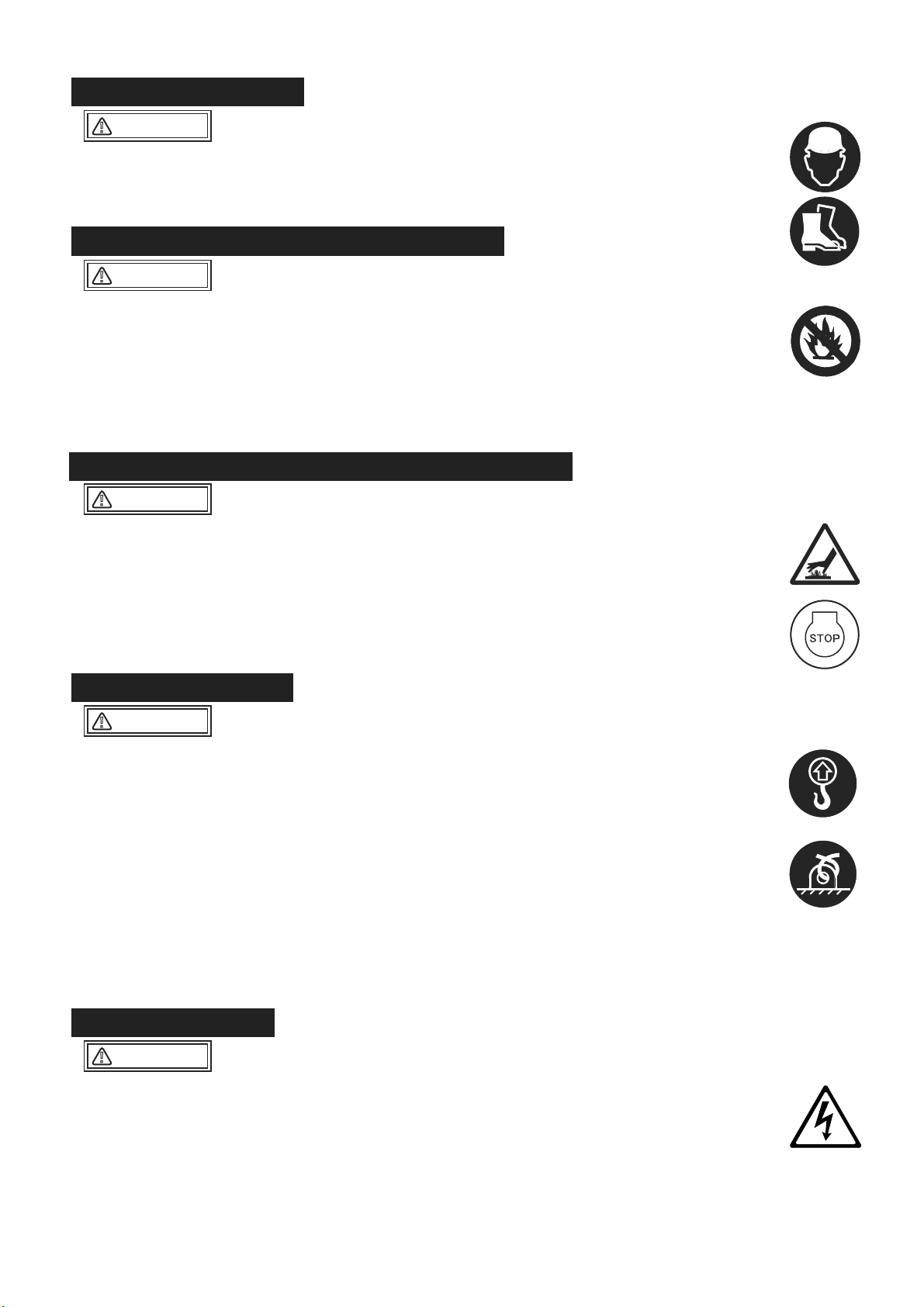
To work safely, wear work clothes of appropriate size, and use suitable protective gear
such as helmet and safety shoes. The work clothes that do not fit the body size might
result in unpredicted injury because the clothes easily get caught by rotating part of the
machine.
When adding fuel
If fuel is filled to the top, it might overflow, and is dangerous.
After refueling, securely tighten the tank cap.
Start your work after the machine temperature drops. Especially, the muffler gets very
hot, and it will pose a danger of burn accident. Also, engine and engine oil as well as
vibrator become hot. Be careful not to get a burn.
If maintenance work is started with the engine running, injury might occur because you
might get caught by the rotating part such as pulley and V-belt. Always stop the engine
before maintenance.
Before maintenance work, remove the starter key of the engine.
Before starting maintenance, always remove the minus (-) terminal of the battery.
When lifting the machine body and the engine, always use a crane. When lifting the
machine and the engine, follow the cautions listed below. If the machine or the engine
is dropped, a serious accident might occur.
To operate a crane, a crane handling qualification is required. Have someone qualified
to handle and operate a crane do this work.
Before lifting, check the parts (especially, hook and anti-vibration rubber) of this
machine for damage and loosening/lack of bolts to secure safety.
Before lifting, stop the engine and shut the fuel cock.
Use sufficiently strong wire rope.
For lifting, use only the lifting hook. Do not use other part for lifting.
Never allow anyone or any animal come under the lifted machine.
For safety, do not lift to the height more than necessary.
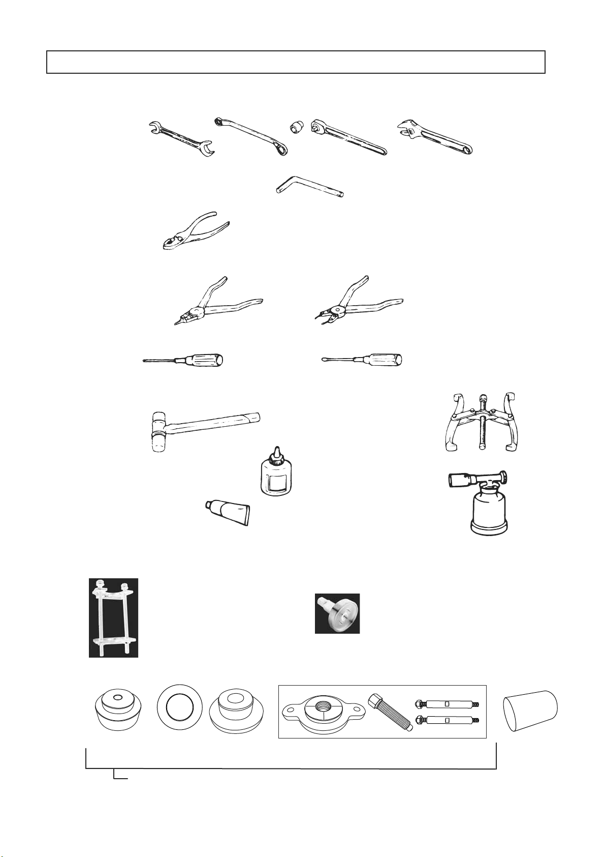
Use an appropriate tool. If the tool that is not suitable for the part is used, not only the
damage on the part, but also unpredicted accident might occur.
Before starting maintenance, always remove the minus terminal of the battery. If short
circuit occurs, ignition might occur.
The battery gas might become a cause of explosion. Do not put fire nearby.
Especially, during charging, flammable gas is released. Do not put fire nearby.
The battery fluid is very toxic. Be careful when handling. If the battery fluid gets on your
skin, eye or on your clothes, wash it off with plenty of water, then see a doctor.
Always refuel in the well ventilated area.
Always refuel after the engine stopped and cooled sufficiently.
Select a flat surface location away from flammable material and Do not overfill
the tank. If spilled fuel, wipe it off well.
Never put fire near the refueling area. (Never refuel while smoking.)
3.2 Clothes And Protective
3.3 Cautions During Refuelinglothes And Protective
3.4 Prevention Of Burn And The Accident Of Getting Caught
䖃
䖃
䖃
䖃
䖃
䖃
䖃
䖃
䖃
䖃
䖃
䖃
䖃
䖃
䖃
䖃
䖃
䖃
䖃
䖃
䖃
WARNING
䟿
3.5 Tools And Equipment
WARNING
䟿
3.6 Handling Of Battery
WARNING
䟿
CAUTION
䟿
CAUTION
䟿
䕿
䕿
䕿
䕿

3
Always use genuine parts.
If inappropriate parts are used, not only it will shorten the machine life, but it might lead
to unpredicted accident.
Tighten bolts and nuts with the tightening torque specified in this maintenance manual.
Over tightening torque and lack of tightening torque not only affect the machine life, but
also might occur unexpected accident.
Unnecessary engine oil, hydraulic oil and fuel should be kept in a container. Never
dump it on the ground or pour into the sewage system such as side ditch.
For disposal of unnecessary engine oil, hydraulic oil and fuel, follow the law and other
regulations.
3.7 Use Of Genuine Parts And Appropriate Oil And V-belt
䖃
䖃
䖃
䖃
WARNING
䟿
CAUTION
䟿
3.9 Disposal Of Waste Material
CAUTION
䟿
3.8 Tightening Torque Of Bolts And Nuts

䠇䞊
4
1. Wrench 10mm 12mm 13mm 14mm 17mm 19mm 22mm 24mm 27mm
Offset wrench/Socket wrench/Adjustable wrench
2. Hexagonal wrench 3/16inch
5mm 8mm 10mm 14mm
3. Plier
4. External snap ring plier/Internal snap ring plier(bent type can be also used)
6. Metal and plastic hammers 7. Pulley puller
9. Torch burner
8. Screw lock agent
(Locktite 242, 271 and 638)
10. Liquid gasket
11. Pressing machine
12. Special jig for hand pump disassembly and assembly
13. Special jig for vibrator disassembly and assembly
4䠊TOOLS
5. Screwdriver, flat and cross
9840-10060
Spring compression tool
9840-10040
Disassembling tool
9840-10070
9849-10011
Bearing insertion jig (driven shaft and drive one) set
Bearing
nsertion
cup
Bearing
insertion
ring
Bearing
insertion
holder
Bearing insertion puller Bearing
remover

㻌
5
5.INSPECTION PROCEDURE
Assembly condition of each component (bolt loosening, defective parts, etc.)
Damage on machine body
Oil check (oil level, dirtiness)
V-belt check (tension, scratch, crack, deterioration, etc.)
Anti-vibration rubber check (scratch, crack, setting, deterioration, etc.)
Engine
Engine speed check (Operating speed, idling speed)
Travel
Check for abnormal noise during operation
Engine oil (when shipped, SAE10W30) (For oil level, please see the table below.)
Vibrator oil
Hydraulic oil (forward/backward travel)
Forward/backward travel switch check
Forward/backward travel speed check
5.1 Appearance Check
5.2 Operation Check
㻔㻝㻕
㻔㻞㻕
㻔㻟㻕
㻔㻠㻕
㻔㻡㻕
㻔㻝㻕
㻔㻞㻕
㻔㻟㻕
㼍㻚
㼎㻚
㼏㻚
㼍㻚
㼎㻚
Screw diameter
M6
M8
M10
M12
M14
The collar screws materials
SS,FCD
Aluminum
Aluminum type+Helisert
N.m
Kgf.cm
ft.lbf
N.m
Kgf.cm
ft.lbf
N.m
Kgf.cm
ft.lbf
N.m
Kgf.cm
ft.lbf
N.m
Kgf.cm
ft.lbf
11.8 - 14.7
120 - 150
8.7 - 10.8
24.5 - 29.4
250 - 300
18.1 - 21.7
58.8 - 68.6
600 - 700
43.4 - 50.6
98.1 - 107.9
1000 - 1100
72.3 - 79.6
117.7 - 127.5
1200 - 1300
86.8 - 94.4
14.7 - 17.7
150 - 180
10.8 - 13.0
32.4 - 35.3
330 - 360
23.9 - 26.0
73.5 - 78.5
750 - 800
54.2 - 57.9
112.8 - 122.6
1150 - 1250
83.2 - 90.4
166.7 - 176.5
1700 - 1800
123.0 - 130.2
Table 1
Standard torque table
MVH-308DSC
MVH-308DSC-PAS
MVH-308DSZ
MVH-308DSZ-PAS
MVH-308GE MVH-308GH MVH-408GH
MVH-408DSC
MVH-408DSC-PAS
MVH-408DSZ
MVH-408DSZ-PAS
MVH-508DSC
MVH-508DSC-PAS
L70V
L70N
YANMAR YANMAR L100V
L100N HATZ 1B30
HATZ 1D81 ROBIN EX27 HONDA GX270 HONDA GX390
HATZ 1B50
1,050cc
1,050cc 1,050cc
1,600cc 1,100cc
1,100cc
1,500cc
2,000cc
Capacity of Lubricant
for Engine
Model
Engine type
Capacity of Lubricant
for Engine
Model
Engine type
Engine oil level table Table 2

6
6䠊SPECIFICATION
Main Dimensions
Compacting Board
Weight
Engine
Parformance
1540
1030
445(595,745)
445(595,745)
860
345(360,375)
HATZ,1B30
Air-cooled 4-cycle
diesel engine
4.9/3300
6.7/3300
3350
○
73/4400
45/4600
0䡚27
6.1
1540
1030
445(595,745)
445(595,745)
860
341(356,371)
YANMAR,L70N6
Air-cooled 4-cycle
diesel engine
4.9/3600
6.7/3600
3600
○
73/4400
45/4600
0䡚27
Overall Length
Overall Height (Handle)
Overall Width
Width
Length
Operating Weight
Manufacturer/Type
Type Of Engine
Maximum Power
Set Engine Revolution
Electric Start
Vibrating Frequency
Centrifugal Force
Max. Traveling Speed
Hand Arm Vibration
(Ahv)
mm
mm
mm
mm
mm
kg
kw/min-1
PS/min-1
r.p.m
Hz/VPM
kN/kgf
m/min
m/sec2
mm
mm
mm
mm
mm
kg
kw/min-1
PS/min-1
r.p.m
Hz/VPM
kN/kgf
m/min
m/sec2
㻹㻻㻰㻱㻸
㻹㼂㻴㻙㻟㻜㻤㻰㻿㼅
㻹㼂㻴㻙㻟㻜㻤㻰㻿㼅㻙㻼㻭㻿
㻹㼂㻴㻙㻟㻜㻤㻰㻿㼆
㻹㼂㻴㻙㻟㻜㻤㻰㻿㼆㻙㻼㻭㻿
㻹㼂㻴㻙㻠㻜㻤㻰㻿㼅
㻹㼂㻴㻙㻠㻜㻤㻰㻿㼅㻙㻼㻭㻿
㻹㼂㻴㻙㻠㻜㻤㻰㻿㼆
㻹㼂㻴㻙㻠㻜㻤㻰㻿㼆㻙㻼㻭㻿
㻹㼂㻴㻙㻡㻜㻤㻰㻿㼆
㻹㼂㻴㻙㻡㻜㻤㻰㻿㼆㻙㻼㻭㻿
1570
1030
500(650,800)
500(650,800)
900
408(423,438)
HATZ,1B50
Air-cooled 4-cycle
diesel engine
6.7/2500
9.1/2500
2350
○
73/4400
55/5600
0䡚28
4.7
1570
1030
500(650,800)
500(650,800)
900
407(422,437)
YANMAR,L100N2
Air-cooled 4-cycle
diesel engine
7.0/3200
9.5/3200
3200
○
73/4400
50/5100
0䡚27
1600
1070
650(800)
650(800)
900
525(540)
HATZ,1D81
Air-cooled 4-cycle
diesel engine
8.9/2500
12.1/2500
2350
○
69/4150
65/6600
0㹼29
5.5
※The number in parentheses is the dimension of the „extension plate(option)‰ with.
„( )‰ : MVH-308,408: (standard type, wide type)
MVH-508: (wide type)
Main Dimensions
Compacting Board
Weight
Engine
Parformance
Overall Length
Overall Height (Handle)
Overall Width
Width
Length
Operating Weight
Manufacturer/Type
Type Of Engine
Maximum Power
Set Engine Revolution
Electric Start
Vibrating Frequency
Centrifugal Force
Max. Traveling Speed
Hand Arm Vibration
(Ahv)
㻹㻻㻰㻱㻸

7
※The number in parentheses is the dimension of the „extension plate(option)‰ with.
„( )‰ : MVH-308,408: (standard type, wide type)
MVH-508: (wide type)
Main Dimensions
Compacting Board
Weight
Engine
Parformance
Overall Length
Overall Height (Handle)
Overall Width
Width
Length
Operating Weight
Manufacturer/Type
Type Of Engine
Maximum Power
Set Engine Revolution
Electric Start
Vibrating Frequency
Centrifugal Force
Max. Traveling Speed
Hand Arm Vibration
(Ahv)
mm
mm
mm
mm
mm
kg
kw/min-1
PS/min-1
r.p.m
Hz/VPM
kN/kgf
m/min
m/sec2
㻹㻻㻰㻱㻸 㻹㼂㻴㻙㻟㻜㻤㻳㻱
1540
1030
445(595,745)
445(595,745)
860
310(325,340)
HONDA,GX270
Air-cooled 4-cycle
petrol engine
6.3/3600
8.6/3600
3600
×
73/4400
45/4600
0㹼27
2.8
1570
1030
500(650,800)
500(650,800)
900
364(379,394)
HONDA,GX390
Air-cooled 4-cycle
petrol engine
8.7/3600
11.9/3600
3200
×
73/4400
55/5600
0㹼28
3.7
1540
1030
445(595,745)
445(595,745)
860
307(322,337)
ROBIN,EX27
Air-cooled 4-cycle
petrol engine
6.6/4000
9.0/4000
3600
×
73/4400
45/4600
0㹼27
3.8
㻹㼂㻴㻙㻟㻜㻤㻳㻴 㻹㼂㻴㻙㻠㻜㻤㻳㻴
Remarks:
Vibration Level is in comply with EU Directive 2002/44/EC and the
value is shown as 3 axix min vibration level.
Test course (Crushed gravel) is in comply with EN500-4.
The above values are sublect to change in case that the machine
is modified or/and the required regulations change.

8
Disassembly and assembly of this machine, with inspection and change of vibrator oil
included, should be done on a horizontal surface area. Before disassembly and
assembly, understand well the normal assembly condition so that you will not make
assembly error.
If oil seal, gasket, packing, O-ring or lock washer is disassembled, replace it with a new
one each time.
The contact surface between vibrator case and vibrator top cover should be sealed with
O-ring. (Clean the contact surface and be careful about O-ring position when
assembling.)
When tightening bolts and nuts, tighten them according to the specified standard torque
and applying the screw lock agent (Loctite, etc.). For bolts and nuts with no
specification, refer to the “Tightening torque list”. (When applying screw lock agent,
degrease and clean the screw part with the brake cleaner, etc.)
Note) The bolts used on this machine are all of the right hand thread.
When disassembling and assembling, work in the maintenance shop without dirt and
dust.
When the bolts applied the screw lock agent (Loctite, etc.) are difficult to loosen, they
loosen easily by heating them with a torch burner. Then, replace the heated bolt with a
new one. It should be a specified high tension bolt (genuine parts).
Use correct tools correctly.
First of all, the machine with battery remove the minus terminal before starting
disassembly. After assembly is done completely, install the minus terminal.
1.
2.
3.
4.
5.
6.
7.
8.
7䠊CAUTIONS BEFORE MAINTENANCE WORK
Tightening torque list
To change the unit to kgf
・
cm, convert with 1 N
・
m = 10.197 kgf
・
cm.
㻔㼡㼚㼕㼠㻦㻌㼗㼓㼒㻙㼏㼙㻘㻌㻝㼗㼓㼒㻙㼏㼙㻩㻥㻚㻤㻜㻢㻢㻡㻺㻙㼏㼙㻕
㻢㼙㼙 㻤㼙㼙 㻝㻜㼙㼙 㻝㻞㼙㼙 㻝㻠㼙㼙 㻝㻢㼙㼙 㻝㻤㼙㼙 㻞㻜㼙㼙
㻠㼀㻔㻿㻿㻠㻝㻕 㻣㻜 㻝㻡㻜 㻟㻜㻜 㻡㻜㻜 㻣㻡㻜 㻝㻘㻝㻜㻜 㻝㻘㻠㻜㻜 㻞㻘㻜㻜㻜
㻢㻙㻤㼀㻔㻿㻠㻡㻯㻕 㻝㻜㻜 㻞㻡㻜 㻡㻜㻜 㻤㻜㻜 㻝㻘㻟㻜㻜 㻞㻘㻜㻜㻜 㻞㻘㻣㻜㻜 㻟㻘㻤㻜㻜
㻝㻝㼀㻔㻿㻯㻹㻟㻕 㻝㻡㻜 㻠㻜㻜 㻤㻜㻜 㻝㻘㻞㻜㻜 㻞㻘㻜㻜㻜 㻞㻘㻥㻜㻜 㻠㻘㻞㻜㻜 㻡㻘㻢㻜㻜
When the mating material is aluminum. 㻝㻜㻜 㻟㻜㻜䡚㻟㻡㻜 㻢㻡㻜䡚㻣㻜㻜
㼀㼔㼞㼑㼍㼐㻌㼐㼕㼍㼙㼑㼠㼑㼞
Material
(Bolts used on the machine are all right-hand thread.)

9
1
3
4
5
7
12
8
910
11
13
2
3
4
5
7
8
11 1415
10
9
29
27
34
35
25
26
28
16
36
38
39
37
40
59
44
46
47
48
45
43
61 6062
18
21
20
19
77
78
63
64
68
75-1
75-2
75-2
67
69
71
51
85
53
80
84
81
76
70
82
83
49
55
56
50
57
58
52
57 58
22
23
MVH-308
CONTROL
13
72
74-1
73-1
74-2
73-2
YANMAR:
L70V / L70N
9392
Fig.4
Fig.3
Nut
Battery holder
Battery
Handle
Fig.1
Rear cover
Stopper
Fig.2
M8 bolts (2 bolts)
㻯㼁㼀
Cyclone cleaner
1.
2.
3.
4.
Remove the stopper at the two locations
on the top portion of the rear cover to
open the rear cover.(Fig.1)
Loosen, but not remove, the M8 bolts (2
bolts) used for cyclone cleaner attach-
ment. Take out the cyclone cleaner down-
ward.(Fig.2)
Take off the nuts and remove the battery
holder. After tilting the battery backward,
disconnect the battery terminal. When
doing so, always disconnect the black ter-
minal on the minus side first.
By holding the top surface handle, pull
upward to remove the battery from the
machine.(Fig.3)
Pay sufficient attention so that the battery ter-
minal will not touch the frame.
CAUTION
䟿
Start your work after the temperature of hy-
draulic oil gets sufficiently lowered.
CAUTION
䟿
After the hydraulic hose is removed, tighten
the caps on both ends to prevent entry of
dust.
CAUTION
䟿
8䠊DISASSEMBLY AND ASSEMBLY
8.1 How To Remove The Battery
8.2 Control Part
(1)
a.
b.
c.
d.
Disassembly
Remove 6 bolts (46), then remove the
handle cover (43).
Remove a bolt (57), then remove the
travel lever (55).
Remove 2 bolts (63) and 2 nuts (62), then
remove the handle grip (59).
Remove the hydraulic hose (51) from
hand pump (50), then remove the hand
pump (50) from the handle (16). (Fig. 4)

10
(2)
䖃
䖃
䖃
(1)
a.
b.
Assembly
Assemble with the reversed procedure
of disassembly, but be careful about
the following points.
Fix the wire (coupler) inside rear cover
(18) with cable tie certainly. (Fig. 6)
When installing the handle assembly to
the engine base, tighten 4 bolts (3) for the
handle brackets of right(1) and left(2) tem-
porarily. Then after adjusting the handle
operation with double nuts (14, 15),
tighten 4 bolts (3) completely. (Fig. 4)
Apply the grease to the shaft and washer.
Disassembly
Remove 4 bolts (35), then remove the belt
cover OUT (33). (Fig. 9)
Remove the V-belt (22).
e.
f.
g.
h.
i.
j.
Remove the wire terminal on engine side.
Remove the hose clamp (33), then
remove the hydraulic hose (51) from the
cylinder on vibrator side. (Fig. 5)
Remove the throttle wire on the engine.
Remove the hour and tachometer (96) on
the rear cover. (Fig. 6)
Remove 6 bolts (21), then remove the rear
cover (18). (Fig. 6)
Remove 4 bolts (3), then remove the
handle (16). (Fig. 4)
Before removing the hydraulic hose, clean
up dirt and soil on its connection part.
CAUTION
䟿
Be very careful not to have your finger get
caught by the hinge part.
CAUTION
䟿
When removing V-belt, after hanging the
waste cloth on the V-belt, then remove the
V-belt by rotating while pulling the waste cloth.
Be very careful not to have your finger get
caught.
In case of the V-belt have damage, it might be
broken by the pulling force. Your body might
damage due to this broken, so be very careful
about level of pulling force.
WARNING
䟿
䖃
䖃
Be very careful not to have your fingers
get caught by the hand pump spring.
Be very careful not to damage the wiring,
when pulling out the hand pump.
CAUTION
䟿
51 53
52
B
C
MVH-308
28
29
30
31
32
19
33
A
18
21
23
24
25
20
54
55
56
23
21
26 25
23
21
25
26
35 36
A
40 43
42
41 39
90
37
E
97
96
91
94
92
93
75
WHITE
ST
(BLACK)
B
(WHITE)
IG
(RED)
BLACK
D
RED
B
60
63
62
65
E
D
WHITE
GREEN
RED BLACK
100
100
76 78
67
77
F
81
82
50
83 84
C
72
80
F
6698
70
99
50
68
68-1
50
71
Fig.6
Fig.5
Hydraulic hose (51)
Cylinder
Hose clamp (33)
For Inspection and Charge of the hydrau-
lic oil, See the “9-8. Inspection & Change
of Hydraulic Oil”.
8.3 Main Body Part
(Separation Of Engine Base And
Vibrating Plate Assembly)
Fig.7
Waste cloth V-belt(22)

11
(2)
a.
b.
c.
d.
䖃
䖃
(1)
a.
b.
c.
Assembly
Assemble with the reversed procedure
of disassembly, but be careful about
the following points.
Apply Loctite #243 to bolts and nuts for
assembling anti-vibration rubber.
Apply Loctite #243 to the all bolts for as-
sembling the BASE AND ENGINE.
When installing the clutch, put the shoe
side of it to engine side.
Use HDPF type V-belt for Mikasa genuine
parts.
During disassembly and assembly, be
careful not to damage each part.
Replace O-ring, oil seal, and packing with
new one.
Disassembly (Fig.10)
Remove 5 bolts (52), then remove the belt
cover, lower (51).
Remove a bolt (43), then remove the
vibrator pulley (40).
Remove 18 bolts that are fixing vibrator
top cover, then remove the vibrator top
cover from vibrating plate.
c. Remove 4 bolts of anti-vibration rubber
that are fixing the engine base(1). then
engine base and vibrating plate AY are
separated by lifting the lifting hook on
main body. (Fig. 9)
During disassembly and assembly of vibrator,
be very careful not to have your fingers get
caught by gear, eccentric rotator, and vibrator
case.
CAUTION
䟿
To secure safety, check the no crack and no
breakage on the guard hook, and check to
tighten the bolts completely, before lifting the
engine base.
Also, use the lifting wire which have sufficient
strong. And use the lifting machine which
have sufficient lifting capability.
WARNING
䟿
35
56
For the machine with COMPAS II, acceleration
sensor and clip (38) have to be removed.
Acceleration sensor Clip (38)
Fig.8
1
1
17 51
52
46
48
49
47
27
30
28
29
31 32
30
33
39
35
57
36
34 35 36
42
44 43
40
B
11
15
13
14
1
12
20
21
22
23
20
24
6
612
16
16
C
D
D
CA
1
2
3
6
6
7
4
8
41
5
5
7
A
B
MVH-308
35
56
38
VIBRATOR (With compaction sensor)
Fig.10
MVH-308
BASE AND ENGINE
(YANMAR: L70N, L70V)
3
4
5
16
2
108
111
7
8
33
34
35
E
D
41
41
42
42
43
43
40
51
52
53
54
55
56
B
45
59
47
57
48
49
58
60
66 65
67
D
64
68
70
71
69
Throttle cable parts
for the engine side
14 15
17
22
18
19
24
26
26
29
30
31
27
25
25
28
61
62
C
A
105
104
106
107
103
100
101
102
102
108
E
110
B
111
12
46
38
39
37
C
72
75
73
74
A
95
116
Fig.9
8.4 Vibrator Partontrol

12
d.
e.
ձ
ղ
ճ
մ
յ
f.
ձ
ղ
ճ
մ
յ
ն
շ
Remove each 2 bolts (7 & 12), then
remove 4 eccentric rotator (6). (Fig.11)
Disassembly of piston(Fig.12)
Remove 4 bolts (34), then remove the cyl-
inder (28).
When removing the cylinder, use the
screw hole for cylinder removal.
By rotating the driven gear (15), the piston
(22) AY come out of the vibrator case.
Remove the stop ring for internal, R-26
(24), from the inside of piston. (Use inter-
nal snap ring plier with bent nose.)
Pull out the piston.
Remove the stop ring for external, S-10
(21), then remove 2 bearings (20) and the
stop ring for internal (24) that was already
removed.
Disassembly of driven shaft (11) AY
Remove the seal cap (17).
The seal cap can remove easily by hitting its
bottom side.
By Inserting the bearing remover (9844-
67730) from seal cap side, the driven shaft
(11) AY come out to piston side, then
remove the bearing outer for piston side.
(Fig.13)
Remove the bearing outer for seal cap
side with the bearing remover, then
remove the driven shaft (11) AY from the
inside of vibrator case. (Fig.14)
Remove the bearing inner from driven
shaft (11) AY with pulley puller. (Fig. 15)
By pushing out the driven gear to opposite
side of piston, Remove the bearing (16) of
opposite side of piston.
In case of it is difficult to push out driven gear,
push out it with pressing machine do not hit it
with a hammer. (Fig. 15)
Remove the knock pin (14), then remove
the piston rod (13). (Fig. 16)
Remove the bearing (16) on piston side.
(Fig. 16)
16×40(P1.5) (7)
16×30(P1.5) (12)
Bolt for drive shaft side Eccentric rotator(6)
Eccentric rotator(6) Bolt for driven shaft side
Fig.11
Piston(22)
Stop ring for external S-14
(21)
Bearing(20)
Stop ring for internal R-26(24) Fig.12
㻥㻤㻠㻠㻙㻢㻣㻣㻟㻜
SEAL CAP SIDE
Bearing remover Fig.13
㻥㻤㻠㻠㻙㻢㻣㻣㻟㻜
Bearing remover
Driven shaft (11)
Bearing outer
S
E
A
L
C
A
P
S
I
D
E
P
I
S
T
O
N
S
I
D
E
Fig.14
Bearing (16)
Piston rod(13)
Knock pin (14)
Driven shaft (11)
Fig.16
PISTON SIDE
OPPOSITE SIDE OF PISTON
Fig.15
Driven gear
Bearing inner
Bearing inner
Bearing (16)

13
g.
ձ
ղ
ճ
մ
յ
ն
շ
(2)
a.
ձ
Disassembly of drive shaft (2) AY
Remove 4 bolts (34), then remove bearing
cover (27).
When removing the bearing cover, use
screw hole for bearing cover removal.
By hitting the end of pulley side on the
drive shaft (2) with plastic hammer, the
drive shaft AY come out to bearing cover
side, then remove the bearing outer for
bearing cover side. (Fig.17)
Remove the oil seal (8), then remove the
bearing outer of pulley side by inserting
the bearing remover (9844-67730) from
pulley side.
Remove the drive shaft (2) AY from the
inside of vibrator case.
Remove the bearing inner from drive shaft
(2) AY with pulley puller.
Remove the stop ring (5) for external, then
remove the drive gear. (Fig. 18)
In case of it is difficult to push out the drive
gear, push out it with pressing machine do not
hit it with a hammer.
Remove the key (3).
Assembly
Degrease and clean the contact surface
between the vibrator case and vibrator
top cover, and other parts.
Assembly of drive shaft
Assemble the key to drive shaft (2), then
press fit drive gear (4). Fix both sides with
stop ring (5) for external.(Fig.18)
Press fit the bearing inner to drive shaft (2).
After Assembling the bearing insert ring to
the bearing inner on the pulley side of
drive shaft (2), assemble the bearing outer
there. Then insert this drive shaft into the
vibrator case. (Fig.20)
Assemble the bearing insertion puller to
threaded hole of bearing cover, then as-
semble the bearing insertion cup between
the center bolt and the bearing housing.
(Fig. 21)
Apply the grease to the drive gear (4)
before press fitting.
The punch mark of drive gear (4)
should put the pulley side. (Fig.19)
Be careful about the direction of the
stop ring. (The edge side should put
outside.)
The flange of bearing inner should put
to the eccentric rotator side.
(Fig.19)
BEARING COVER SIDE
PULLEY SIDE
Fig.17
Fig.18
Stop ring (5)
Drive gear
Drive shaft (2)
Key (3)
ղ
ճ
մ
䖃
䖃
䖃
䖃
PULLEY SIDE
Fig.19
Drive gear (4)
Drive shaft
Flange
Flange
Bearing inner
PUNCH MARK
PULLEY SIDE
Bearing inner
Bearing outer
Bearing
insertion ring
Bearing insertion ring Fig.20
Center bolt
BEARING COVER SIDE
bearing
insertion cup
bearing
insertion puller
bearing insertion cup
Fig.21

14
յ
ն
շ
Press fit the bearing outer of pulley side by
tightening the center bolt of bearing inser-
tion puller. (Fig. 22)
Remove the bearing insertion ring of ճ
from the drive shaft (2).
Press fit the bearing outer of bearing cover
side with the bearing insertion puller and
bearing insertion cup. At this time, press fit
the bearing outer 2 to 3 mm deep from the
mounting surface for bearing cover.
(Fig. 23, 24)
Assemble the O-ring (30) to the bearing
cover (27), then assemble it to the vibrator
case for the bearing cover side. After as-
sembled the bearing cover, check the
thrust gap of drive shaft. (Standard value:
0.5mm to 1.0mm).
Insert oil seal (8) into vibrator case of
pulley side of drive shaft. (Fig.25)
Assembly of driven shaft
Assemble an eccentric rotator (6) to the
pulley side (inside: straight) on the driven
shaft (11) by tightening a bolt (12). Then,
press fit bearing (16) to driven shaft.
(Fig.26, 27)
ո
չ
b.
ձ
Fig.22
Bearing inner
Bearing inner
PULLER SIDE
OPPOSITE SIDE
OF PULLER
Bearing outer
Bearing outer
BEARING COVER SIDE
bearing insertion puller
bearing insertion cup
Bearing outer
Fig.23
Fig.24
Press fit 2 to 3 mm deep from the mounting surface
for bearing cover.
Fig.25
Oil seal (8)
O-ring (30)
Bearing cover (27)
Fig.26
Piston rod (13)
Knock pin (14)
Driven shaft (11)
Bearing (16)
Driven gear
PISTON SIDE (INSIDE:TAPERED)
PULLEY SIDE (INSIDE:STRAIGHT)
䖃
䖃
䖃
䖃
Assemble the bearing after applying
grease.
Assemble the O-ring after applying
grease.
When inserting oil seal, make sure that
there is no bend on oil seal and no
damage on the lip.
Apply Loctite #243 to the bolts for assem-
bling the bearing cover.
Tightening torque 35 N㺃m
CAUTION
䟿

15
ղ
ճ
մ
յ
Insert the piston rod (13) from the piston
side (inside: tapered) of driven shaft, then
insert knock pin (14) into the hole of piston
rod through the groove of driven shaft.
(Fig. 28)
Put the eccentric rotator of driven shaft to
the upper side, then push the piston rod
into the driven shaft.
Put the punch mark of driven gear to the
pulley side, then insert it to the driven
shaft. At this time, set the driven gear by
turning its punch mark to the right side
when seeing from the pulley side. (Fig. 29)
By seeing from the pulley side, while rotat-
ing driven gear to the right, insert the
knock pin into the spiral groove of driven
gear.
In case of the driven gear is assembled
correctly, when pulling out the piston
rod, the punch mark of driven gear and
the threaded holes for eccentric rotator
of driven shaft should be set in the
same straight line. (Fig. 30)
Press fit the bearing (16), then fix the drive
gear (15). (Fig. 31)
Press fit the bearing inner to the driven
shaft (11).
The flange of bearing inner should put
to the eccentric rotator side.
Press fit the bearing outer of pulley side
from the inside of vibrator case with the
bearing insertion puller and bearing inser-
tion holder. (Fig. 32)
ն
շ
ո
Fig.28
Driven shaft (11)
Knock pin (14)
Push the piston rod
PULLEY SIDE Knock pin (14)
PUNCH MARK
Fig.29
Pull the piston rod
The punch mark and threaded holes for
eccentric rotator are set in
the same straight line.
PUNCH MARK
Hole for
eccentric rotator
Hole for
eccentric rotator
Fig.30
Bolt 16㽢30(P1.5)(12)
Bearing (16)
PISTON SIDE (INSIDE:TAPERED)
PULLEY SIDE (INSIDE:STRAIGHT)
Driven shaft (11)
Eccentric rotator (6)
Fig.27
PRESS
Fig.31
Press fit the bearing (16)
Bearing
insertion puller
Bearing
insertion holder
OUTSIDE OF CASE
࣋ࣜࣥࢢ࢘ࢱ࣮
INSIDE OF CASE
Tighten the center bolt Fig.32

16
չ
պ
c.
Insert from the piston side of driven shaft
(11) AY into the vibrator case, then align
the punch mark between the drive gear
and driven gear. (Fig. 33)
Press fit the bearing outer of piston side
with the bearing insertion puller and bear-
ing insertion cup. At this time, press fit the
bearing outer 2 to 3 mm deep from the
mounting surface for cylinder cover.
See the “a. Assembly of drive shaft շ”
on P14 .
Assemble the eccentric rotators to the
drive shaft and driven shaft. (Fig.34)
Assembly of piston
First, insert the stop ring for internal (24)
to piston rod. (Fig. 35)
Insert 2 bearings (20) to piston rod, then
fix them with stop ring for external (21).
(Fig. 35)
Assemble the UHS packing (23) to piston
(22).
(After applying hydraulic oil to UHS pack-
ing, assemble it with your finger.) (Fig. 36)
d.
ձ
ղ
ճ
Driven side Drive side
Punch mark
(Driven side)
Punch mark
(Drive side)
Fig.33
Stop ring for
internal
Stop ring for
external
Bearing 6000ZZSG
Fig.35
䖃
䖃
䖃
Check the bolts size.
Apply Loctite #263 to the each bolts (7 &
12).
Do not turn the drive shaft and driven
shaft, when tightening the bolts for eccen-
tric rotator with torque wrench.
Tightening torque 275 N㺃m
CAUTION
䟿
䖃
䖃
Apply the grease to the bearing insertion
part of piston rod.
Use the genuine parts for bearing (20).
CAUTION
䟿
䖃
䖃
䖃
Make sure that there is no scratch and no
damage on the piston.
Make sure that there is no damage on the
UHS packing.
Be careful about the direction of the UHS
packing.
CAUTION
䟿
When press fitting the bearing outer of piston
side, push the piston rod until the end of
groove of driven shaft.
CAUTION
䟿
Be very careful not to have your fingers get
caught by gear, eccentric rotator, and vibrator
case.
WARNING
䟿
Bolt 16×40 (P1.5)(7)
(Drive side) Bolt 16×30 (P1.5)(12)
(Driven side)
Eccentric
rotator
Eccentric
rotator
Eccentric
rotator
Eccentric
rotator
Fig.34

17
④
e.
f.
g.
Assemble the piston (22) to bearings (20),
then fix it by assembling the stop ring for
internal (24) that was already inserted.
Assemble the O-ring (30) to the cylinder
(28), then assemble it to the vibrating for
the piston side. After assembled the
cylinder, check the thrust gap of driven
shaft.
(Standard value: 0.5〜1.0mm)
Assemble the connector (29), air release
bolt (31), and packing (32) to the cylinder.
Assemble the seal cap (17) to the vibrator
case at the opposite side of the cylinder.
By the above steps, the assembly of the
vibrator is completed. As a final step, turn
the drive shaft with your hand to make
sure that it rotates smoothly.
If it does not rotate smoothly, adjust it by
hitting the side of gear with a plastic
hammer lightly.
Add the new vibrator oil (10W-30 of SAE
grade or higher) to vibrator case as speci-
fied level.
Degrease the contact surface between the
vibrator case and vibrator top cover, then
after assembling O-ring to the vibrator
case, assemble them by tightening bolts.
(Fig. 37)
Use the engine oil (SAE10W-30) as
vibrator oil.
The oil quantity is 600cc (0.6L) / Oil
level height is 9mm.
Measure the vibrator oil quantity correctly.
(If it is more than the specified value, it
might cause over-load. If it is less than the
specified value, noise and shortening of
bearing life might occur.)
h.
●
●
●
●
●
●
When assembling the piston, push it with
your hand or hit it with a plastic hammer
lightly.
When assembling the stop ring for inter-
nal, use internal snap ring plier with bent
nose. Make sure that it assembles into the
groove certainly.
After assembled the piston, make sure
that it rotates smoothly.
The edge side of the stop ring should put
outside.
CAUTION
!
●
●
●
Apply Loctite #243 to the bolts (34) for as-
sembling cylinder.
Tightening torque 73.6N
・
m
When inserting the piston to the cylinder,
be careful not to damage USH packing.
Assemble the O-ring after applying
grease.
CAUTION
!
Apply the seal tape around the connector
(29).
CAUTION
!
Never hit the gear teeth.
CAUTION
!
Be very careful not to have your fingers get
caught between gear and eccentric rotator.
WARNING
!
UHS packing
Piston
Fig.36
○
○
Apply Loctite #243 to the bolts.
Tightening torque (35 N
・
m)
Tighten the bolts in a crisscross pattern.
①
⑤
⑦
⑧
②
③
④⑥
⑨
⑩
⑱⑰
⑯
⑮
⑭
⑬
⑫
⑪
Fig.37
This manual suits for next models
5
Table of contents
Other Mikasa Construction Equipment manuals