4
4.5 Precaution to truck with road board about unloading
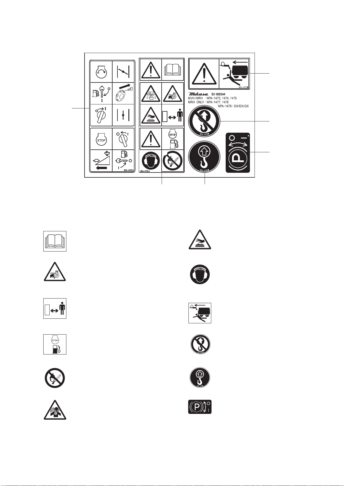
4.6 Precaution in lifting
Lifting license is required for up loading and lowering with crane. Be sure to work with a licensing holder in crane..
●
●
●
●
●
●
●
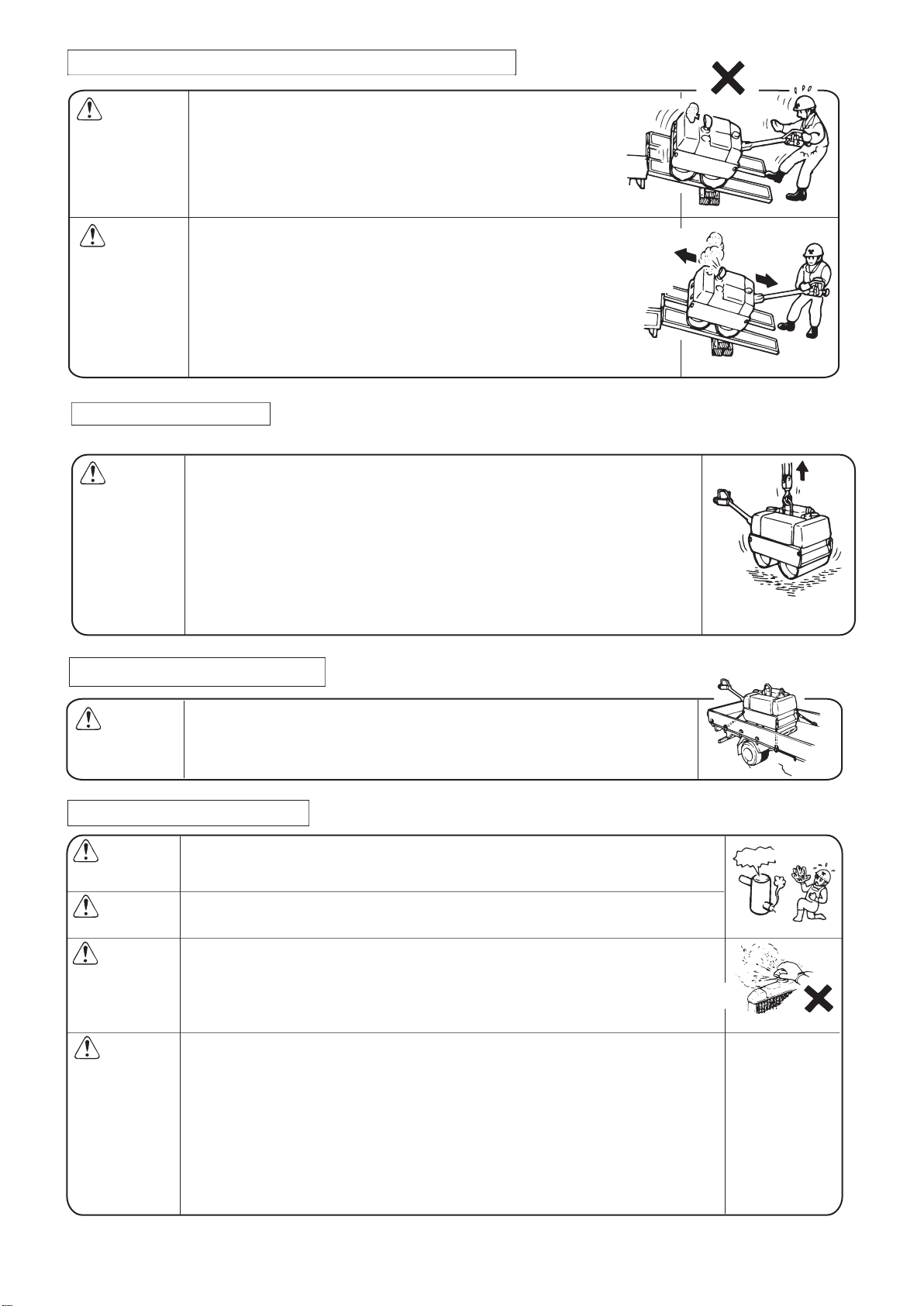
CAUTION: Before lifting work, be sure to confirm security. Check any breakage of body
parts(Lifting hook, Shock absorbing rubber, Safety guard, etc) or
looseness/falling off of screws.
When lifting, stop the engine first.
Use wire rope good enough with strength.
Manage to use one-point lifting hook, to be straight and avoid shock.
Avoid any sudden lifting up and down work, especially done by crane device
with hydraulic excavator.
Keep any person or animal away from under the lifted machine.
For security, do not lift the machine up more than it required.
4.7 Precaution in transportation
●
●
●
WARNING: When transporting, stop the engine for security.
Drain fuel completely before transporting the machine.
Engage Parking Brake, and put ring stopper in front & rear of drums to roll on,
then use wire rope with tow catches for security.
4.8 Precaution in maintenance
●
●
●
●
●
●
●
●
●
CAUTION:
WARNING:
CAUTION:
WARNING:
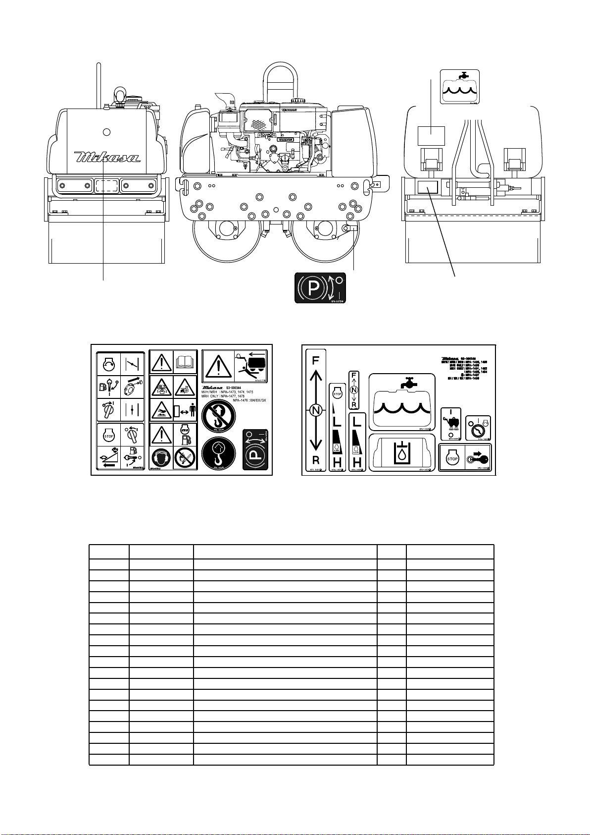
Muffler
Burn warning
Appropriate maintenance is always required for safety operation. Improper mainte-
nance on traveling device may lead serious accident especially. Pay full attention to
maintain the machine in good condition.
Be sure to stop engine always before checking the machine.
Do not tough with muffler when it is hot.
Be sure not to remove radiator cap while engine still warms. Remove Cap after
engine is cooled down enough.
Battery liquid is dangerous drug, and pay special attention to handle. When added
battery liquid to skin, eye, clothes, wash it completely with much quantity of water,
and medical check by medical specialist is recommended.
In case of hydraulic distribution pipes removed, release hydraulic pressure in piping
by all means. High pressure in hydraulic circuit may give a worker danger.
Lubrication oil and engine oil may be very hot, and bring burn injury, and do not start
maintenance while oil remains hot.
After performing any maintenance, check the conditions of salfety components and
general safety of the machine. In particular, check bolts and nuts thoroughly.
Electromagnetic clutch system consists of soft materials a lot.
Slapping, dropping, added force may cause bruise and transformation, and in the
event, it leads malfunction and a lack of torque.
●
●
●
●
●
●
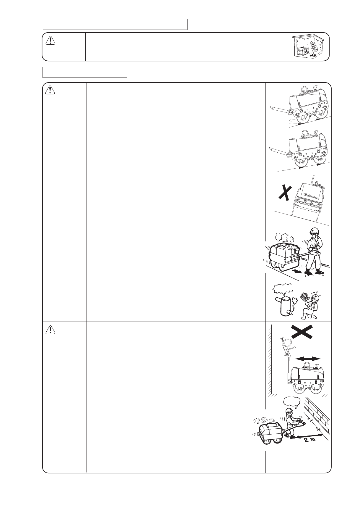
WARNING:
CAUTION:
Keep engine speed as specified during the work and traveling.
Especially in inclined area, keep the specified speed. Otherwise,
engine may stop and the roller goes down by its weight.
If it happened, move Travel Lever to “Stop” position(Neutral
position) promptly, which lets the drum not to roll automatically.
Operator should stand at right side or left side of Handle Bar, and
be sure not to go straight back of Handle Bar.
Do unloading work under instructions of the designated leader.
Truck, road board and rolling drum must keep away from any mud,
oil, snow, ice and etc. Then start unloading work after cleaning them fully.
Engage parking brake with Transporter, and set ring stopper at drum rolls
Match the span of road board according to a roller width, and keep
the incline angle max at 15 degree.
Fix a course precisely before running onto a road board.
Generally, do loading in forward motion, and do unloading in
reverse motion.