TABLE OF CONTENTS
1. Preface
2. Applications, Warnings, Power Transmission of Machine
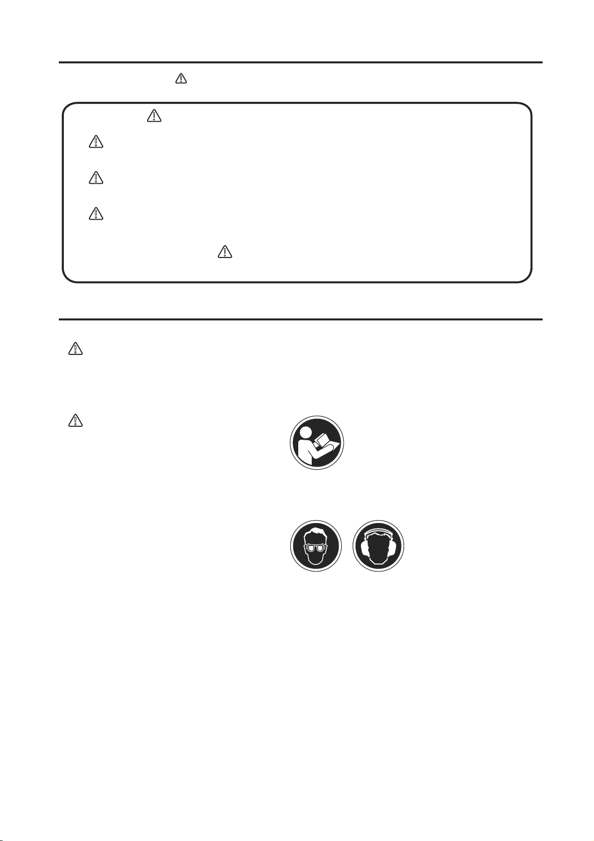
3. Warning Symbols
4. Safety Precautions
5. Specifications
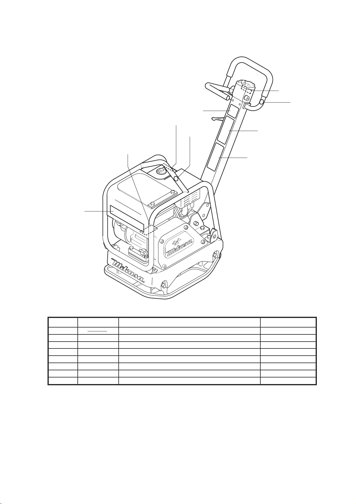
6. Appearance
7. Inspection Before Operation
8. Operation
9. Stopping the Machine
10. Transportation
11. Storage
12. Regular Check and Adjustment
13. Troubleshooting
4-1 General Precautions
4-2 Refueling Precautions
4-3 Location and Ventilation Precautions
4-4 Precautions Before Starting
4-5 Precautions During Work
4-6 Lifting Precautions
4-7 Transportation and Storage Precautions
4-8 Maintenance Precautions
4-9 Labeling Positions
4-10 Description of Symbols Used on Warning Labels
6-1 Outside Dimensions
6-2 Parts and Component
8-1 Starting
8-2 Operation
10-1 Loading and Unloading
10-2 Transportation Precautions
12-1 Inspection and Maintenance Schedule Table
12-2 Changing the Engine Oil
12-3 Cleaning the Air Cleaner
12-4 Checking/Changing the V-belt and Clutch
12-5 Checking/Changing the Vibrator Oil
12-6 Checking/Changing the Hydraulic Oil
13-1 Gasoline Engine
13-2 Main Body
.................................................................................... 1
....... 1
.................................................................... 3
.................................................................. 3
.................................................... 3
.................................................. 4
........................... 4
....................................... 4
............................................. 4
....................................................... 4
.................... 5
........................................... 5
....................................................... 6
...... 7
.......................................................................... 9
.............................................................................10
.....................................................10
................................................ 11
.................................................. 12
............................................................................... 13
..................................................................... 13
.................................................................. 16
............................................................ 17
....................................................................... 18
............................................ 18
...................................... 18
.................................................................................. 18
............................................ 19
........... 19
........................................... 20
........................................... 20
................ 20
......................... 21
....................... 21
.................................................................... 23
....................................................... 23
................................................................ 24