Milestone pro MP-IP500E User manual
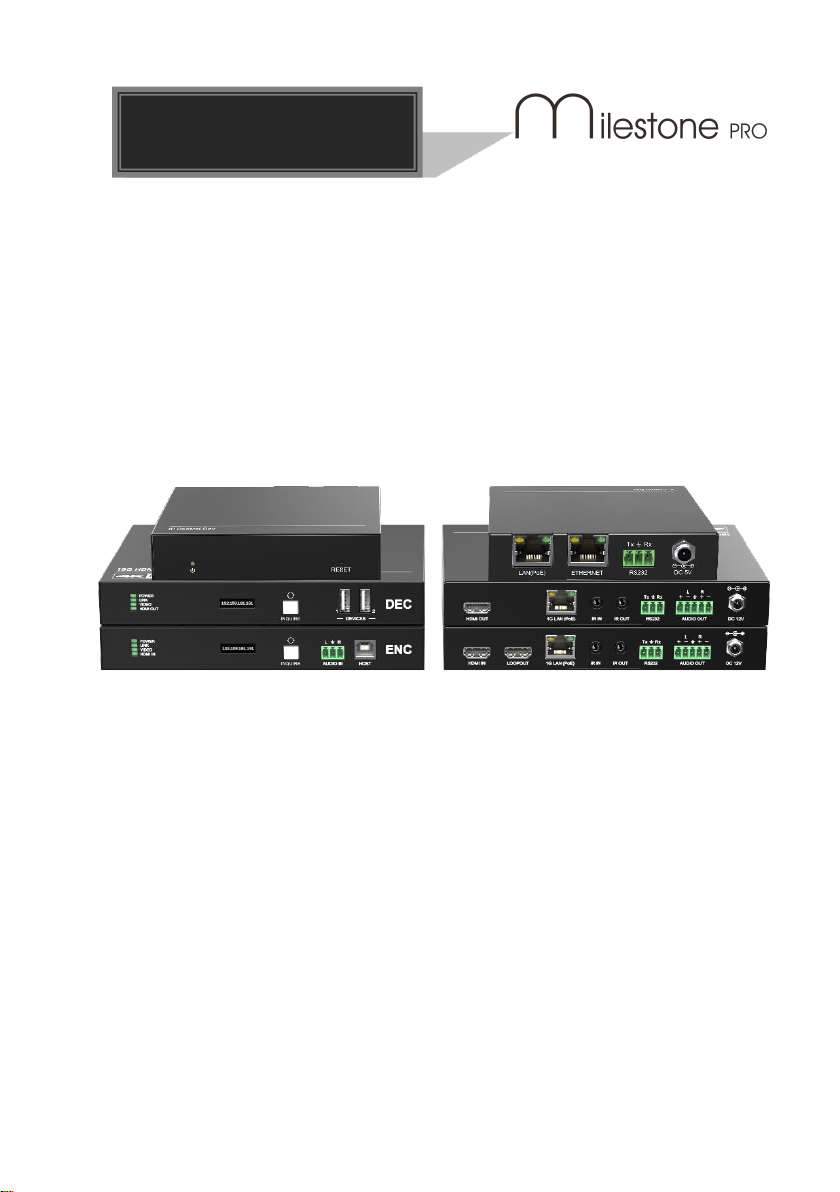
MP-IP500E & MP-IP500D & MP-IP500C1
18G HDMI over 1G IP Encoder & Decoder
All Rights Reserved
Version: MP-IP500_2023V1.0
User Manual

18G HDMI over IP Streaming Extender
Preface
Read this user manual carefully before using the product. Pictures shown in this
manual are for reference only. Different models and specifications are subject to real
product.
This manual is only for operation instruction, please contact the local distributor for
maintenance assistance. The functions described in this version were updated till July
13, 2023. In the constant effort to improve the product, we reserve the right to make
functions or parameters changes without notice or obligation. Please refer to the
dealers for the latest details.
FCC Statement
This equipment generates, uses and can radiate radio frequency energy and, if not
installed and used in accordance with the instructions, may cause harmful interference
to radio communications. It has been tested and found to comply with the limits for a
Class A digital device, pursuant to part 15 of the FCC Rules. These limits are designed
to provide reasonable protection against harmful interference in a commercial
installation.
Operation of this equipment in a residential area is likely to cause interference, in which
case the user at their own expense will be required to take whatever measures may be
necessary to correct the interference.
Any changes or modifications not expressly approved by the manufacture would void
the user’s authority to operate the equipment.

18G HDMI over IP Streaming Extender
SAFETY PRECAUTIONS
To ensure the best performance from the product, please read all instructions carefully
before using the device. Save this manual for further reference.
⚫Unpack the equipment carefully and save the original box and packing material for
possible future shipment.
⚫Follow basic safety precautions to reduce the risk of fire, electrical shock and injury
to persons.
⚫Do not dismantle the housing or modify the module. It may result in electrical shock
or burn.
⚫Using supplies or parts not meeting the products’ specifications may cause
damage, deterioration or malfunction.
⚫Refer all servicing to qualified service personnel.
⚫To prevent fire or shock hazard, do not expose the unit to rain, moisture or install
this product near water.
⚫Do not put any heavy items on the extension cable in case of extrusion.
⚫Do not remove the housing of the device as opening or removing housing may
expose you to dangerous voltage or other hazards.
⚫Install the device in a place with fine ventilation to avoid damage caused by
overheat.
⚫Keep the module away from liquids.
⚫Spillage into the housing may result in fire, electrical shock, or equipment damage.
If an object or liquid falls or spills on to the housing, unplug the module immediately.
⚫Do not twist or pull by force ends of the optical cable. It can cause malfunction.
⚫Do not use liquid or aerosol cleaners to clean this unit. Always unplug the power to
the device before cleaning.
⚫Unplug the power cord when left unused for a long period of time.
⚫Information on disposal for scrapped devices: do not burn or mix with general
household waste, please treat them as normal electrical wastes.

18G HDMI over IP Streaming Extender
Table of Contents
1. Product Introduction ...............................................................................................1
1.1 Features .......................................................................................................1
1.2 Package List .................................................................................................1
2. Specification ..........................................................................................................2
2.1 Encoder ........................................................................................................2
2.2 Decoder ........................................................................................................3
3. Panel Description...................................................................................................4
3.1 MP-IP500 Encoder ........................................................................................4
3.2 MP-IP500 Decoder........................................................................................5
3.3 IP Control Box...............................................................................................6
4. System Connection ................................................................................................7
4.1 Usage Precaution..........................................................................................7
4.2 Connection Type ...........................................................................................7
4.3 System Diagram............................................................................................8
4.4 Hardware Setup ............................................................................................9
5. Operation of TCP/IP .............................................................................................10
5.1 General Information.....................................................................................10
5.2 Project Setting.............................................................................................11
5.3 Drag and Drop.............................................................................................12
5.4 Video Wall...................................................................................................13
5.5 Encoder ......................................................................................................14
5.6 Decoder ......................................................................................................16
5.7 Rounting .....................................................................................................18
5.8 Video Wall...................................................................................................19
5.9 Setting ........................................................................................................21
5.10 Upgrade....................................................................................................22
6. Panel Drawing .....................................................................................................23
7. Troubleshooting & Maintenance............................................................................24
8. Customer Service.................................................................................................25

18G HDMI over IP Streaming Extender
1
1. Product Introduction
The MP-IP500 is a network AV extender with HDMI encoder and decoder up to
resolution 4K@60Hz 4:4:4, HDR. It is designed for HDMI transmission over IP network
with control signals at distance up to 100m over CATx cable. It works with one control
PC (Wake on IP control box) and one 1GbE Switch to control a variety of functions.
The MP-IP500 provides one of the most advanced IP Streaming solutions on the
market utilizing Aspeed technology, which synergizes various IP/AV standards to work
together as one.
The MP-IP500 features 4K video with 1 frame latency from encoder to decoder, Video
wall, 1G Ethernet, IR, RS232, etc. It can be controlled by the Web-UI.
Compares with traditional HDBaseT matrix AV Switching, MP-IP500 features low cost,
easy installation, more interoperability and flexibility. It is ideal for distributing AV over 1
Gigabit Ethernet in enterprises and other large-scale installations.
1.1 Features
⚫Streams 4K video with 1 frame latency.
⚫Supports HDMI video resolution up to 4K@60Hz 4:4:4 8bit.
⚫Transports RS232 and IR signal to any units.
⚫Supports Video Wall mode up to 9x9 screens.
⚫Selectable output resolutions up to 4K scaling ability.
⚫Additional 3-pin terminal block for audio embedding.
⚫IP control box for TCP/IP control.
1.2 Package List
For each unit, they have different package, sold separately.
1x MP-IP500E
1x MP-IP500D
MP-IP500C1
⚫2x Mounting Kit
⚫2x Mounting Kit
⚫2x Mounting Kit
⚫4x Rubber feet
⚫4x Rubber feet
⚫4x Rubber feet
⚫1x 3-pin Terminal
Block
⚫1x 5-pin Terminal
Block
⚫1x 3-pin Terminal
Block
⚫1x 5-pin Terminal
Block
⚫1x User Manual
⚫1x 5V1A adapter
⚫1x User Manual
⚫1x User Manual
Note: Please contact your distributor immediately if any damage or defect in the
components is found.

4K IP Streaming Extender
2
2. Specification
2.1 Encoder
Input
Video Input
(1) HDMI
Video Input Connector
(1) Type-A female HDMI
HDMI Input Resolution
Up to 4K@60Hz 4:4:4 8bit
Audio Input
(1) Analog Audio In
Audio Input Connector
(1) 3-Pin terminal block
Output
Video Output
(1) IP Stream (1) HDMI
Video Output Connector
(1) RJ45, (1) Type-A female HDMI
HDMI Output Resolution
Up to 4K@60Hz 4:4:4 8bit
Audio Output
(1) IP Stream (1) De-embedding Output
Audio Output Connector
(1) RJ45, (1) 5-Pin terminal block
General
Control
(1) IR IN, (1) IR OUT, (1) RS232, (1) host
Control Connector
(2) 3.5mm jack, (1) 3-pin terminal block (1) USB-B
Operation Temperature
-10℃ ~ +55℃
Storage Temperature
-25℃ ~ +70℃
Relative Humidity
10%-90%
Power Consumption
7.8W (Max)
Dimension (W*H*D)
180 x 142.7 x 25 mm
Net Weight
570g

18G HDMI over IP Streaming Extender
3
2.2 Decoder
Input
Video Input
(1) IP Stream
Video Input Connector
(1) RJ45
Output
Video Output
(1) HDMI
Video Output Connector
(1) Type-A female HDMI
HDMI Output Resolution
Up to 4K@60Hz 4:4:4 8bit
Audio Output
(1) Analog audio output
Audio Output Connector
(1) 5-Pin terminal block
Audio Sample Rate
Support 48 kHz, 96 kHz, 192 kHz
THD+N
< 0.05% (-80dB), 20Hz –20KHz bandwidth, 1KHz
sine at 0dBFS level (or max level).
Frequency Response
20Hz –20KHz, ±1dB
SNR
> 90 dB, 20Hz - 20KHz bandwidth.
Crosstalk Isolation
< - 80 dB, 10KHz sine at 0dBFS level (or max level
before clipping).
Noise Level
< - 80 dBu
General
Control
(1) IR IN, (1) IR OUT, (1) RS232
Control Connector
(2) 3.5mm jack, (1) 3-pin terminal block
Operation Temperature
-10℃ ~ +55℃
Storage Temperature
-25℃ ~ +70℃
Relative Humidity
10%-90%
Power Consumption
11.52W (Max);
Dimension (W*H*D)
180 x 142.7 x 25 mm
Net Weight
570g
18G HDMI over IP Streaming Extender
4
3. Panel Description
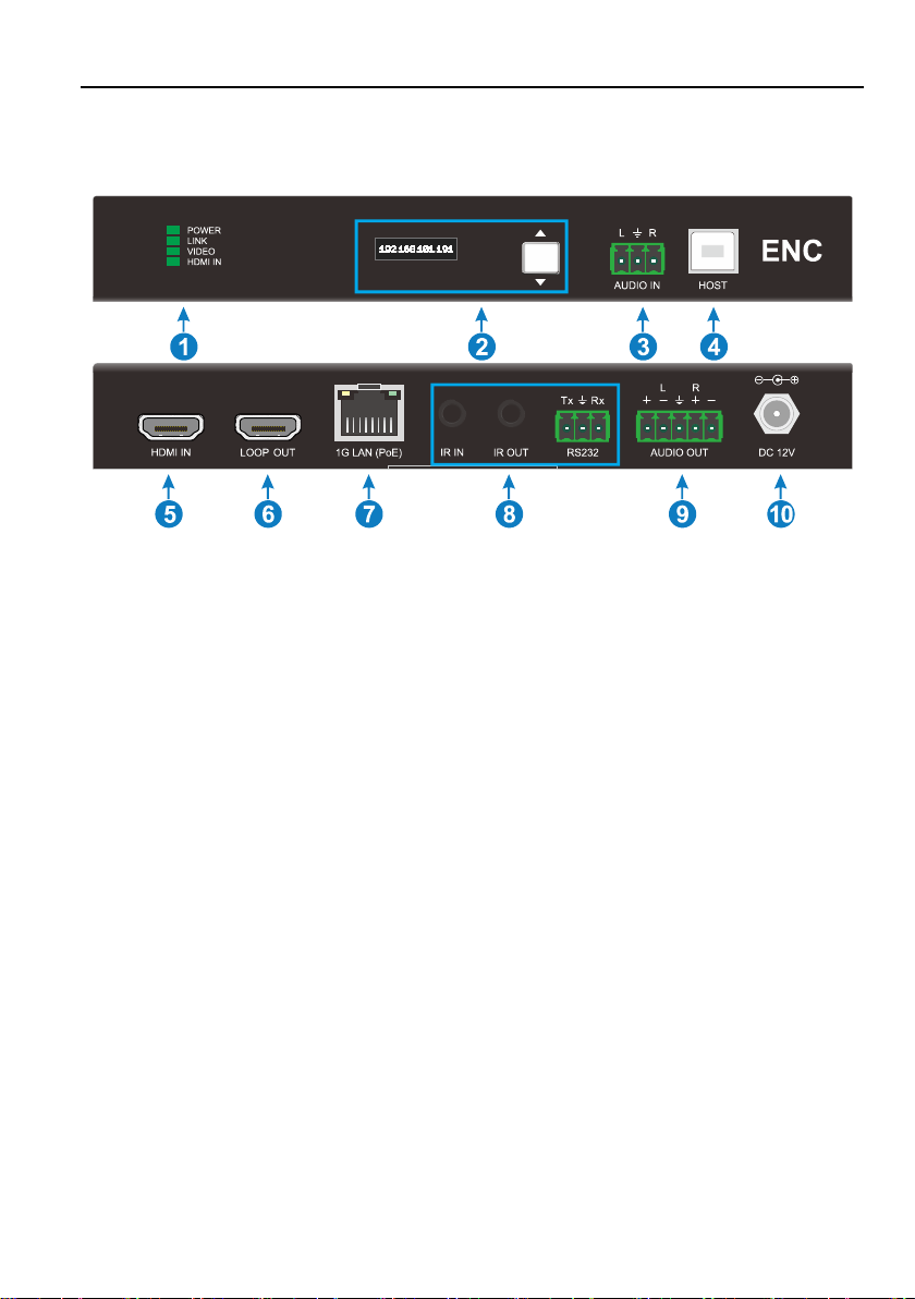
3.1 MP-IP500 Encoder
1. POWER LED: The LED illuminates green when power is supplied.
LINK LED: The LED indicates green if 1G LAN port is connected.
VIDEO LED: The LED illuminates green when the stable video signal is detected.
HDMI IN: The LED illuminates green when 5V signal is detected.
2. OLED Screen: Show the unit information of IP address, firmware version and
MCU version.
Button: Recycle switch the information show in OLED screen.
3. AUDIO IN: 1x 3-pin terminal block, embedding the analog audio in the source.
4. HOST: 1x USB-B 2.0, connect the PC
5. HDMI IN: 1x HDMI Type-A female port, connecting to the video source.
6. LOOP OUT: 1x HDMI output port for the video loop out.
7. 1G LAN(PoE): 1x RJ45 port, connecting to the IP Network for the IP stream
output. The port also supports IEEE 802.3af-2003 PoE to power for the unit.
8. Control: IR input, IR output and RS232 support unicast and multicast
communicate between encoder and decoder.
9. AUDIO OUT: 1x 5-pin terminal block for the audio de-embedding.
10. DC 12V: Connect to the DC12V1A power adapter.

18G HDMI over IP Streaming Extender
5
3.2 MP-IP500 Decoder
1. POWER LED: The LED illuminates green when power is supplied.
LINK LED: The LED indicates green if 1G LAN port is connected.
VIDEO LED: The LED illuminates green when the stable video signal is detected.
HDMI OUT: The LED illuminates green when 5V signal is detected.
2. OLED Screen: Show the unit information of ENC IP address, DEC IP address,
Firmware version and MCU version.
Button: Recycle switch the information show in OLED screen.
3. DEVICES: 2x USB-A 2.0 connect to the USB devices.
4. HDMI OUT: 1x HDMI output port for the video out.
5. 1G LAN(PoE): 1x RJ45 port, connecting to the IP Network for the IP stream input.
The port also supports IEEE 802.3af-2003 PoE to power for the unit.
6. Control: IR input, IR output and RS232 support unicast and multicast
communicate between encoder and decoder.
7. AUDIO OUT: 1x 5-pin terminal block for the audio de-embedding.
8. DC 12V: Connect to the DC12V1A power adapter.
18G HDMI over IP Streaming Extender
6
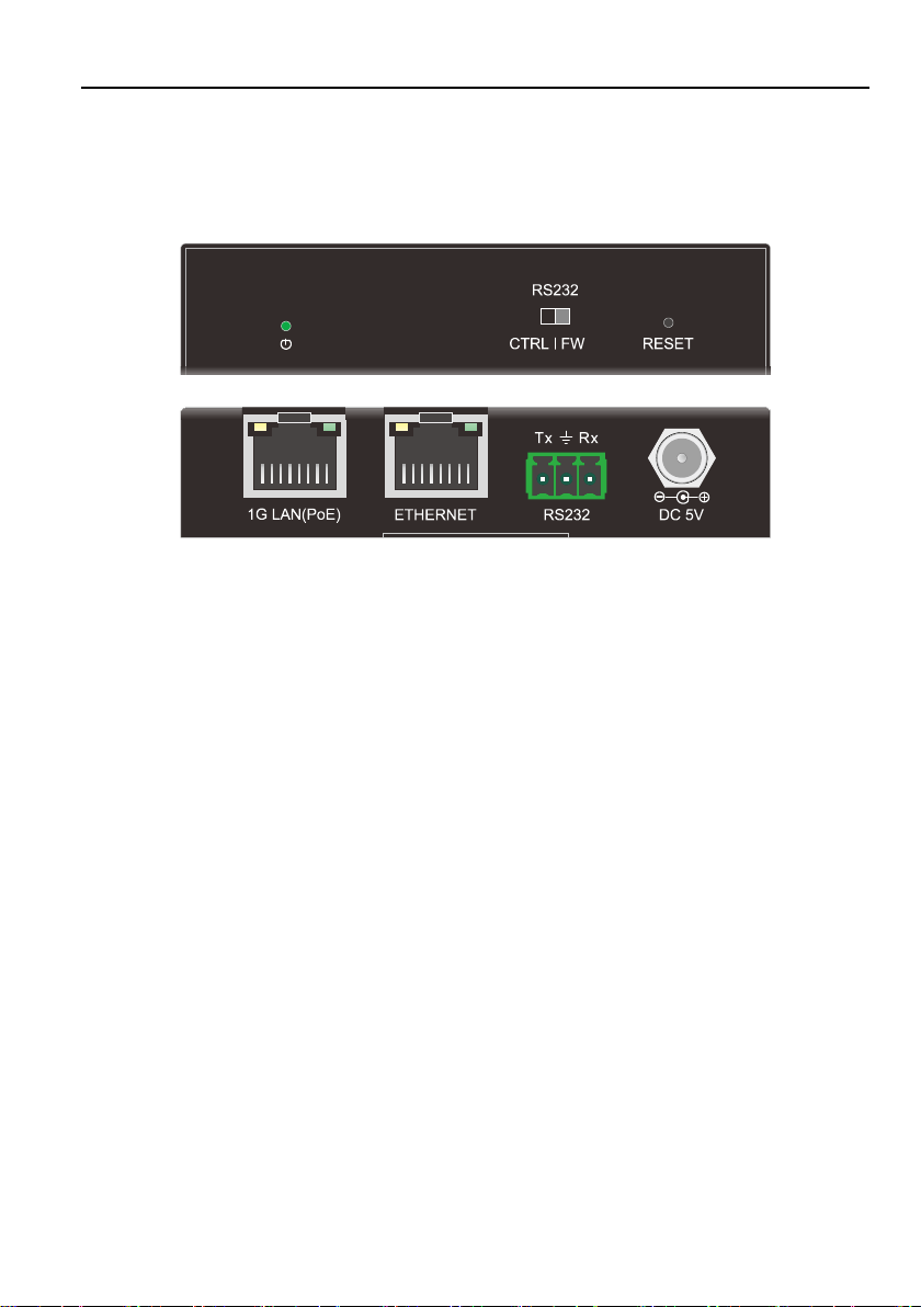
3.3 IP Control Box
The MP-IP500C1 control box allows third party control of the multicast system use
TCP/IP, RS232.
1. Power LED: Illuminates green when power on.
2. DIP Switch: Select the RS232 mode, controlling or firmware upgrade.
3. Reset: Long press 3s for factory reset.
4. 1G LAN(PoE): Connect to the IP Network for the control. The port also supports
IEEE 802.3af-2003 PoE to power for the unit.
5. ETHERNET: Connect to the network where the control system existing.
6. RS232: Connect to the PC for the RS232 control.
7. DC5V: Connect to the DC5V1A power adapter.

18G HDMI over IP Streaming Extender
7
4. System Connection
4.1 Usage Precaution
⚫Make sure all components and accessories are included before installation.
⚫The system should be installed in a clean environment with proper temperature and
humidity.
⚫All of the power switches, plugs, sockets, and power cords should be insulated and
safe.
⚫All devices should be connected before being powered on.
4.2 Connection Type
There are three types of possible applications:
Extender (Point-to-Point)
In a point-to-point configuration, there is no need for a switch. Distribute full, transfer
4K@60Hz 4:4:4 resolution up to 100m.
Splitter (One-to-Many)
With only one MP-IP500 as transmitter and one 1G Ethernet switch, any A/V signal can
instantly distributed to a near limitless number of receivers and screens, any number of
times.
Matrix Switcher (Many-to-One, Many-to-Many)
The combination of switching and splitting enables a completely scalable matrix
system. Independently route video, audio and control signal from any source to any
endpoint.
18G HDMI over IP Streaming Extender
8
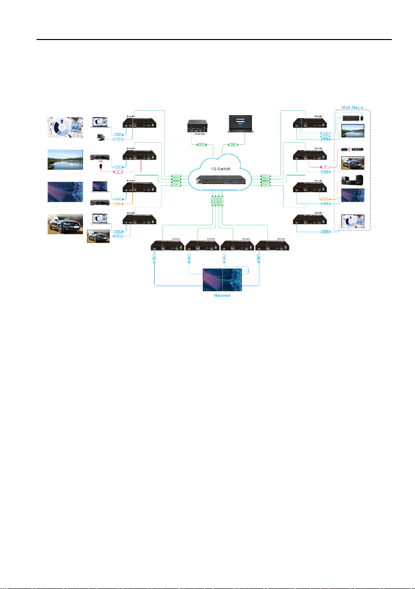
4.3 System Diagram
The following diagram illustrates typical input and output connections that can be
utilized with the MP-IP500:
Matrix System

18G HDMI over IP Streaming Extender
9
4.4 Hardware Setup
Please follow the steps below to complete the system installation:
1) Connect the power supply (12V DC) to the power connectors (or powered by the
switch via PoE).
2) Connect the video/graphics source device to the HDMI input connector on each
Encoder unit.
3) Connect the video display device to the HDMI output connector on each
DECODER unit.
4) (Optional) Connect RS232 devices as needed if you want to test RS232 serial
extension between Encoder and DECODER units.
5) (Optional) Connect GbE compatible Ethernet devices as needed for testing the 1
Gig Ethernet ports of any Encoder or DECODER units.
6) (Optional) Connect compatible IR emitter modules to the IR output connectors of
any Encoder or DECODER.
7) (Optional) Connect compatible IR receiver modules to the IR input connectors of
any Encoder or DECODER.
8) Connect a 1G Ethernet cable from the 1GbE port each Encoder and DECODER
unit to any available 1GBaseT port.
9) Connect one IP Control Box to the network.
10) Connect the control PC to the ETHERNET port of one IP control box or one of the
1GbE switch (except the management/console port of the switch).
11) The hardware setup is now completed.
18G HDMI over IP Streaming Extender
10
5. Operation of TCP/IP
5.1 General Information
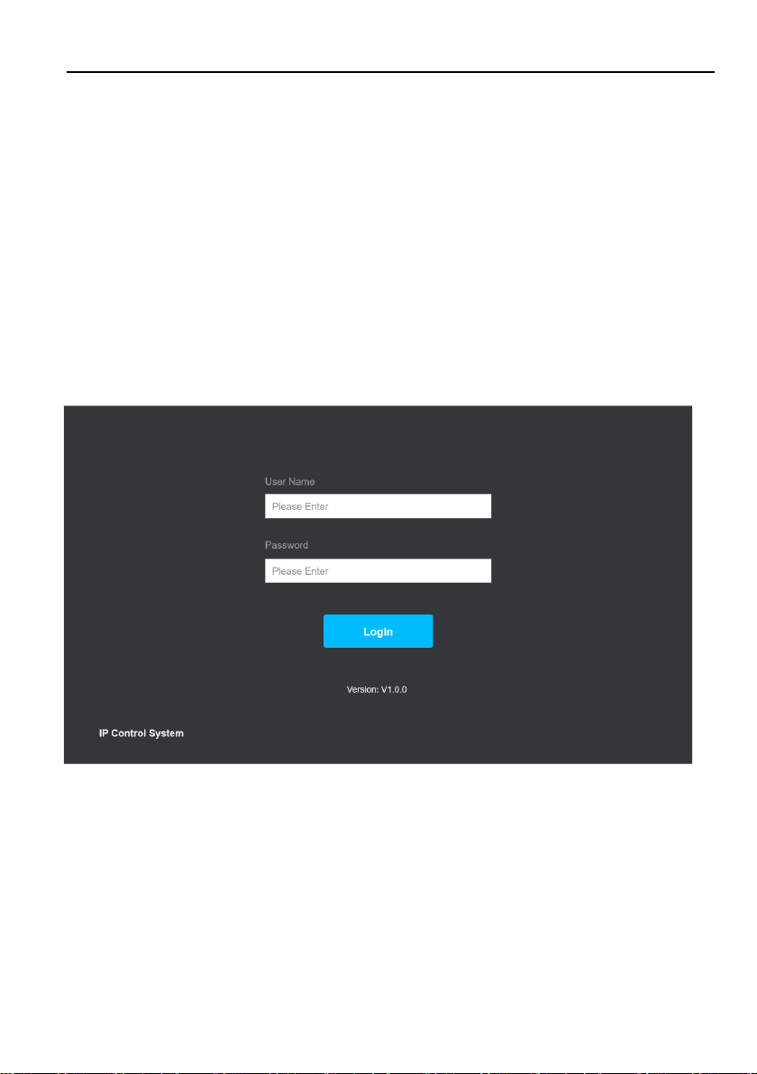
After connecting a control box in the Local Area Network, we can login in the GUI to
control the units.
IP Address: 192.168.0.178
Subnet Mask:255.255.255.0
Username: admin
Password: admin
Type 192.168.0.178 in the internet browser, it will enter the login webpage
Please type the username and password, and then click Login.

18G HDMI over IP Streaming Extender
11
5.2 Project Setting
In the first login in, it will require to setting a project, scan the unit and find the encoder
and decoder.
Click Next for more setting.
Modify the devices name of each unit. And setting the EDID, IP Address.
View button is for open a preview image. Reboot button is use for restart the unit.

18G HDMI over IP Streaming Extender
12
5.3 Drag and Drop
In this page, you can build the connect between the encoders and decoders.
In unicast mode, it only supports point to point link.
In multicast mode, it supports matrix switch.
Click the button to switch the unicast/multicast mode of units.
18G HDMI over IP Streaming Extender
13
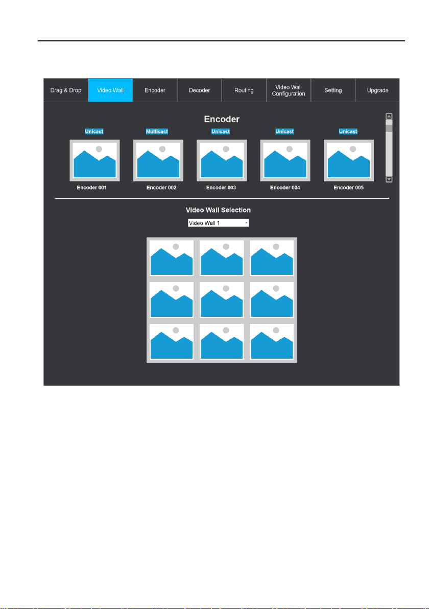
5.4 Video Wall
After configuration of the video wall (see the section 5.8), we can switch the video wall
source in this page.

18G HDMI over IP Streaming Extender
14
5.5 Encoder
In this page, we can see all the encoder in this project.
We can set each unit or batch setting.

18G HDMI over IP Streaming Extender
15
⚫Modify the device name, IP address.
⚫Select the audio source: HDMI or Analog input.
⚫Turn on/off CEC passthrough.
⚫Turn on/off audio de-embedding.
⚫Setting EDID: select on the list or user defined.
⚫RS232 setting.
⚫Casting mode select.
⚫Remove the unit from the project.
⚫Reboot the unit.
⚫Factory reset the unit.
For the batch setting, we can setting the Devices name, IP address, RS232 and casting
mode.

18G HDMI over IP Streaming Extender
16
5.6 Decoder
We can find all the decoder and setting each unit in this page.
For the OSD, we can set the font size, font color, back ground color and background
transparency.
Click the setting button to turn on the setting page.
This manual suits for next models
2
Table of contents
Other Milestone pro Media Converter manuals


Popular Media Converter manuals by other brands

Polytron
Polytron QAM 12 LAN manual

Accton Technology
Accton Technology EC3002 installation guide

PIEXX
PIEXX ToneLCD manual

Baumer
Baumer Hubner Berlin HOGS 100 Mounting and operating instructions

Baumer
Baumer HOG 28 Mounting and operating instructions

Storm Interface
Storm Interface 450 Series Engineering manual

Sensoray
Sensoray 3101 Hardware manual

DirectOut Technologies
DirectOut Technologies MADI.SRC user manual

ESTEC
ESTEC LM 128P manual

Allied Telesis
Allied Telesis IMC2000 Series installation guide

Sena
Sena DirectPort-USB user guide

SAFARI Montage
SAFARI Montage SD/HD MPEG Digital Encoder Installation and setup guide


