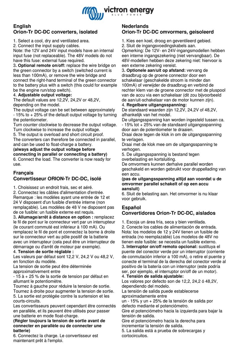
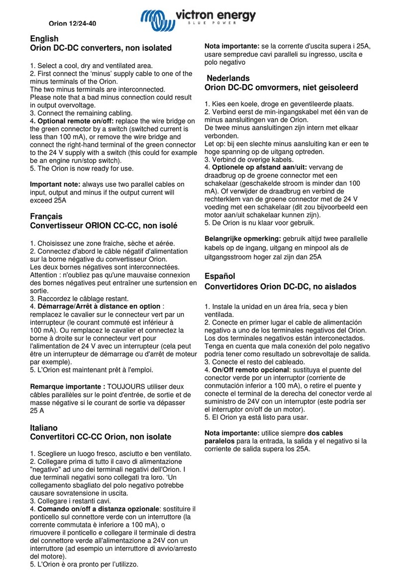
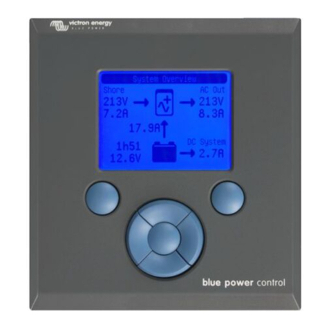
Victron energy Buck-Boost 100A User manual

Manual
EN
Handleiding
NL
Manuel
FR
Anleitung
DE
Manual
SE
Руководство по
эксплуатации
RU
Appendix
Buck-Boost DC-DC Converter
25A / 50A / 100A


1
EN NL FR DE SE RU Appendix
Introduction
Full range programmable DC-DC converter 25/50/100A.
The solution for battery charging problems with Euro 5 and Euro 6 engines and alternator charge current
protection with lithium systems.
General description:
The Buck-Boost converter series is a program of specially developed DC-DC converters for fully-controlled charging
of an extra battery or a battery bank. Application is necessary in the case of vehicles with an alternator intelligent
control, and for general protection of the alternator in lithium systems.
Alternators of Euro 5 and 6 engines, which are controlled by the onboard electronics, often supply too low charging
voltage even with the engine running. As a result, a Buck-Boost converter is necessary to charge the extra battery. In
the case of lithium systems, the alternator must be protected against overload, resulting in overheating, which arises
because the voltage control of the alternator cannot anticipate zero resistance of lithium battery systems.
To ensure that the start battery of the vehicle is always loaded with priority, the units of Buck-Boost series will only
provide power when the engine is running. This is possible thanks to the built-in engine running detection and the
related programmable time-delayed switching. This also prevents the onboard voltage of the vehicle from becoming
too low. It is not necessary to intervene in the system of the vehicle, install a separate motor run sensor or intervene
in the CAN bus system. Apart from this detection, the Buck-Boost series equipment can also be switched on with a
programmable input.
The Buck-Boost series is fully programmable through a very simple and easy PC application. The output current has
an automatic limitation that is adjustable. The automatic stop becomes active as soon as the temperature comes
close to a pre-set maximum.
The output voltage is fully adjustable and is independent of the input voltage due to the automatic Buck-Boost control.
This control also ensures that the current will never exceed the set value. Also not when the input voltage is higher
than the output voltage.
Applications:
•Charging an extra/second battery (bank) with an eco
alternator of a Euro 5 or Euro 6 engine.
•Charging lithium batteries with an alternator without
temperature protection.
•Automatic activation and deactivation of the
alternator charge current, based on a unique engine
running detection protocol.
General features:
•Buck-Boost converter is fully programmable
•Input voltage 10..30 Vdc
•Output voltage 10..30 Vdc
•Output current (max.at 12V) 25, 50 or 100A
•Output current (max.at 24V) 12.5, 25 or 50A
•Adjustable current limiter
•Automatic activation when engine running
•Output for activation/deactivation of loads
•Battery temperature monitoring (optional)
•LED status indicators
•M8 connections
•USB for configuration/monitoring
•CAN-bus for control purposes and CAN-bus Temp
Sensor communication
•Battery monitor
2
The Buck-Boost range is fully programmable by means of a Windows application – TSConfig – that is very simple and
intuitive to use.
TSConfig.
We recommend updating your TSConfig program regularly so that you always have the latest version. Updates are
available at https://www.victronenergy.com/support-and-downloads/software
25A
50A
100A

3
EN NL FR DE SE RU Appendix
Warnings
Read this manual carefully before installing and commissioning the equipment.
Store the manual carefully and pass it on to a new user of this product!
Explanation of the symbols used
DANGER!
Safety instruction:
Failure to comply will result in death or serious
injury.
WARNING!
Safety instruction:
Failure to comply may result in death
or serious injury.
CAUTION!
Failure to do so may result in property damage
and limit the
functionality of the product.
INSTRUCTION
Additional information for operating the
product.
General safety instructions
The manufacturer cannot be held liable for damage in the following cases:
• mounting or connection errors
• product damage by mechanical impacts and overvoltage
• modifications of the product without the express permission of the manufacturer
• use with purposes other than those described in the manual
For safety reasons when installing and using electrical appliances, always observe the risks of electric shock, fire risk
and injury!

4
General safety
DANGER!
Use a fire extinguisher suitable for electrical appliances in the event of a fire. Always have a
fire extinguisher at hand in the premises and use it appropriately.
WARNING!
•Use the equipment only according to the instructions.
•Make sure that the plus (+) and minus (-) poles never touch each other.
•Disconnect the product from the battery when:
– performing cleaning and maintenance
– replacing a fuse (only by specialists)
•for disassembly of the product:
– Disconnect all connections.
– Ensure that all inputs and outputs are energized.
•If the product or connecting cable is visibly damaged, the product should not be put
into operation.
•If the connection cable of this product is damaged, it must be replaced by a qualified
personnel.
•Repairs to this product may only be performed by the manufacturer. Improper repairs
can lead to considerable hazards.
•This product must not be used by children and by persons with reduced physical,
sensory or mental abilities or lacking necessary experience and knowledge. Users
should have insight into the dangers that the use of the product entails.
•Electrical appliances are not toys. Store and use the product for this reason out of
reach of children, and ensure that children do not play with the product.
CAUTION!
•Before commissioning, ensure that the set voltage of the product corresponds to the
system voltage of the existing energy supply.
•Pay attention that other objects cannot cause a short circuit at the contacts of the
device.
•Store the product in a dry and cool place.
Safety when assembling the product
DANGER!
Do not mount the product in places where there is a risk of a gas or dust explosion.
WARNING!
Provide a stable mounting!
The product must be securely mounted and attached to prevent it falling, dropping, and
preventing contact of the connections with surrounding objects.
CAUTION!
•Do not expose the product to heat sources (solar radiation, heating, etc.).
•Avoid additional heating of the product.
•Install the product in a dry place protected against splashing water.

5
EN NL FR DE SE RU Appendix
Safety at the electrical connection of the product
DANGER!
Risk of fatal electric shock!
•When working on the electrical system, make sure that someone is around who can
help in case of an emergency.
•When installing on boats: Improper installation of electrical appliances on boats can
cause corrosion damage to the boat. Have the product connected by a qualified
electrician.
WARNING!
•Provide a sufficient cable intersection.
•Mount the cables so that they cannot be damaged by doors or hoods. Crushed
cables can lead to life-threatening situations, and should be replaced.
•Install the cables in such a manner that they cannot be tripped over, and any damage
to cables is excluded.
CAUTION!
•Use wire conduits if cables are to be routed through sheet walls or other feedthroughs
with sharp edges.
•Do not combine an AC cable and DC cable in the same channel (wire conduit).
•Do not loosen the conduits or sharply kink them.
•Attach the cables with the right materials and tools.
•Never pull the cables, take sufficiently long cable lengths of sufficient intersection in
relation to its length.
Safe use of the product
WARNING!
If the product is used in environments with lead-acid batteries, the room should be well
ventilated. Explosive hydrogen gas is released from these batteries, which can be ignited by
electric sparks.
CAUTION!
•Do not use the appliance
– in a salt-containing, damp or wet conditions
– nearby aggressive vapours
– near flammable materials
– in explosive environments
•Before use, check that the cables and connections are dry.
•Always disconnect the power supply when working on the product.
•Parts of the product may still be energized after the product has been disconnected.
•Do not disconnect cables when the product is still in use.
CAUTION!
•Prevent the product from being covered or being installed in a space that is too small.
•Provide proper ventilation.

6
Safety when handling batteries
WARNING!
Batteries may contain harsh and corrosive acids. Avoid any and all physical contact with the
battery fluid. In case of skin contact with battery fluids, wash the affected areas of the skin with
water.
In case of injuries due to acids, please be sure to consult a physician.
CAUTION!
•When working with batteries do not wear metal objects such as watches or rings.
•Lead-acid batteries can cause short-circuit currents that can lead to serious burns.
Risk of explosion!
•Wear protective goggles and safety clothing when working on batteries. When
working with batteries, do not touch your eyes .
•Do not smoke and make sure there are no sparks nearby the engine or the battery.
•Do not attempt to charge frozen or defective batteries. In this case, place the battery
in a frost-free room and wait until the battery is at ambient temperature. Then start the
loading procedure.
CAUTION!
•Use only rechargeable batteries.
•Use sufficient cable intersections.
•Secure the positive cable with a fuse.
•Prevent metal parts from falling on the battery. This may result in sparks or short-
circuiting of the battery and other electrical parts.
•Pay attention to the correct polarity when connecting.
•Please observe the battery and equipment manufacturers’ instructions listed in
corresponding manuals.
•In case the battery needs to be removed, always disconnect the ground connection
first. Then disconnect all other connections and disconnect all consuming points from
the battery before removing it.

7
EN NL FR DE SE RU Appendix
Connection
Simplified diagram: Connections:
OUT
GND
IN
IN : Converter
input
(alternator/starter battery)
GND : GND (chassis)
OUT : Converter output (extra battery)
Pin 1 : Input/output (purple wire)
Pin 2 : Input/output (green wire)
When Pin 1 or Pin 2 is being used, use the resistors
supplied to ensure safety.
This is no longer necessary in the most recent models
(recognisable by their ridged housing).
Microcontroller
Buck/boost controllers
Sensor
3-axis
1 in/out
2 in/out
temp
Relay driver
Converter
output
GND
Converter
input
CAN Bus connection
USB connection
OUT
GND
IN

8
OUTPUT led indicator
INPUT led indicator
LED indicators
The Buck-Boost DC-DC converter is equipped with two RGB LEDs.
The IN LED has the following functions:
Green: The converter is switched on (by the engine running detection, or by applying a voltage on pin 1).
Yellow:The input voltage is lower than the set threshold to allow the converter
to switch on.
Red: The internal temperature is higher than the set safety threshold. The converter is
switched on
Blue: Short light pulses = the engine running detection is active, the converter turns on after a delay.
Flashes slowly = the converter is switched off and blocked for switching on due to
A too low input voltage.
The OUT LED has the following functions:
Green: The converter is switched off. The connected battery has a correct terminal voltage.
Yellow:The converter is switched off. The connected battery has too low a terminal voltage.
Red: The converter is switched off. The connected battery is empty or the battery is not connected.
Purple: The converter is switched on and supplies power to the connected battery and/or electrical
consuming points.
Flashing purple: The converter is switched off. When the converter starts up, the set voltage of the
second battery is too low (safety circuit 31 is active).
The normal alerts of each LED blinks slowly for power saving (Setting 27).
Engine running detection
The converter has a unique engine running detection in order to be able to detect a running vehicle
engine. This prevents the converter from charging the starter battery if the alternator does not supply
power.
The converter is switched on:
When the engine is running and the supply voltage is >= (adjustable) volts and any (adjustable) minute
blocking is over.
Pin 1 input (as an alternative to the engine running detection)
The converter may also be switched on with a switch or relay contact.
Switch on:
The converter is switched on:
If pin 1 input >= 2 volts, and the supply voltage is >= (adjustable) volts and any blocking is over.
Important when installing!
Basic settings
At the time of commissioning, the following basic settings shall be applied:
Setting 12V – 12V 24V – 24V 12V – 24V
20 Output voltage 14.4V 28.8V 28.8V
22 Maximum output current
60% of the current supplied by the vehicle’s alternator (max.)
24 Undervoltage threshold 11.8V – 12.2V 23.8V – 24.2V11.8V – 12.2V

9
EN NL FR DE SE RU Appendix
On-board voltage
The on-board voltage under setting 24 of the TSConfig software shall not be set too low. This value may
be adjusted by a qualified electrician only!
Input and output fuse
Use the following input and output fuse and cable intersection depending on the Buck-Boost type:
12 VOLTS INPUT
Buck-Boost type
Fuse value / Ampères
Cable thickness (< 5 metres)
25A
40 Ampère (A)
16 mm2
50A *)
60 Ampère (A)
35 mm
2
100A *)
125 Ampère (A)
50 mm2
12 VOLTS OUTPUT
Buck-Boost type
Fuse value / Ampères
Cable thickness (< 5 metres)
25A
40 Ampères (A)
16 mm
2
50A *)
60 Ampères (A)
35 mm2
100A *)
125 Ampères (A)
50 mm2
24 VOLTS INPUT
Buck-Boost type
Fuse value / Ampères
Cable thickness (< 5 metres)
25A
30 Ampères (A)
16 mm2
50A *)
40 Ampères (A)
35 mm2
100A *)
80 Ampères (A)
50 mm2
24 VOLTS OUTPUT
Buck-Boost type
Fuse value / Ampères
Cable thickness (< 5 metres)
25A
30 Ampère (A)
16 mm2
50A *)
40 Ampère (A)
35 mm
2
100A *)
80 Ampère (A)
50 mm
2
*) CAUTION. In order to use the 50A or 100A, the alternator must have sufficient charging capacity to be able to
supply the maximum input voltage that the converter requires. For details, please see the input voltage (max.) in
the table.
Connection
First connect all GND cables to the converter, the battery and the chassis, and then only the positive (+) cable.
This is important because in the converter everything refers to GND.
When the two plus (+) cables are connected without GND, the potential difference between the plus (+) connections
ensures uncontrolled and unsecured currents!
Always check that the GND connection on the middle M8 connection is correctly connected.
The converter has no reverse polarity protection!
Converter operation
The Buck-Boost DC-DC converter operates on the principle of buck-boost.
This means that the input voltage may be both higher and lower than the set output voltage. The amount
of the charge current remains in both situations always fully under control.
A brief overview of possible conversions:
Buck-Boost type
12V
– 12V Default
24V
– 24V Default
12V
– 24V Default
25A charging current max.
25A
15A
10A
50A charging current max.
50A
25A
20A
100A charging current max.
100A
50A
50A

10
Charging current limiter
The output current is determined by the following factors:
Setting: The maximum desired charging current is set via the USB connection
(with the Windows application TSConfig).
Temperature: If the converter temperature comes close to the set maximum temperature, the charging
current is automatically limited. As a result, the temperature of the Buck-Boost inverter is
never inadmissibly high.
TSConfig application
The Buck-Boost converters can be configured extensively with TSConfig software. This software also includes a
monitor window, where real-time operation of the converter can be tracked.
The following image shows a screenshot of the TSConfig software:
The TSConfig software and manual can be downloaded from: https://www.victronenergy.com/support-and-
downloads/software
Wiring diagram
Starter
Battery
Service battery
Alternator
50A
100A

11
EN NL FR DE SE RU Appendix
Technical specifications
Buck-Boost DC-DC
Converter
25A 50A 100A
Input voltage range
10 to 30 Volt
Threshold undervoltage
10V
Output voltage range
10-30V
Maximum charging current
12V : 25A 24V : 15A
12V : 50A 24V : 25A
12V: 100A 24V: 50A
Power consumption
Converter switched off, LEDs
from energy saving mode)
7mA
Input voltage on/off (pin 1, purple wire)
Threshold voltage ‘On’
> 2V
Maximum input voltage
30V
Output pin 1 and pin 2
Output voltage as enabled
Vpinout = Vin
Maximum voltage (per pin)
Ipinout = 1.5A
GENERAL
Operating temperature range
-25...+60°C
Ambient temperature
Max power at 40°C
Weight
0.6 kg
1.4 kg
4.1 kg
Dimensions
165 x 120 x 30 mm
213 x 120 x 30 mm
288 x 162 x 95 mm


1
EN NL FR DE SE RU Appendix
Introductie
Full range programmable DC-DC converter 25/50/100A.
Dé oplossing voor acculaadproblemen bij Euro 5 en 6 motoren en dynamo laadstroombescherming bij lithium
systemen.
Algemene omschrijving:
De Buck-Boost converter serie is een programma van speciaal ontwikkelde DC-DC converters voor het volledig
gecontroleerd laden van een extra accu of accubank. Toepassing is noodzakelijk bij voertuigen met een intelligente
dynamo regeling, en ter bescherming van de dynamo bij lithium systemen in het algemeen.
Dynamo’s van Euro 5 en Euro 6 motoren, die worden aangestuurd door de voertuigelektronica, geven met draaiende
motor vaak een te lage laadspanning af. Hierdoor is een Buck-Boost converter noodzakelijk
om de extra accu te laden. Bij lithium systemen dient de dynamo beschermd te worden tegen overbelasting met als
gevolg oververhitting, wat ontstaat omdat de spanningsregeling van de dynamo niet kan anticiperen op de nihil
weerstand van lithium accu systemen.
Om ervoor te zorgen dat de startaccu van het voertuig altijd met prioriteit vol geladen is, zal de Buck/Bost converter
pas stroom leveren zodra de motor loopt. Dit is mogelijk door de ingebouwde motorloopdetectie en de daaraan
gerelateerde programmeerbare inschakelvertraging. Hierdoor wordt tevens voorkomen dat de boordspanning van het
voertuig te laag kan worden. Het is niet nodig om in het systeem van het voertuig in te grijpen, een separate
motorloopdetectie te installeren of in het CAN bus systeem in te grijpen. In plaats van deze detectie kan de Buck-
Boost serie ook worden ingeschakeld met een programmeerbare input.
De Buck-Boost serie is volledig programmeerbaar door middel van een zeer eenvoudige en overzichtelijke Windows
applicatie.
De uitgangsstroom heeft een automatische begrenzing die instelbaar is. De automatische begrenzing wordt actief
zodra de temperatuur in de buurt van een ingesteld maximum komt.
De uitgangsspanning is volledig traploos instelbaar en is door de automatische Buck-Boost regeling onafhankelijk
van de ingangsspanning. Deze regeling zorgt er ook voor dat de stroom nooit de ingestelde waarde zal
overschrijden. Ook niet in het geval dat de ingangsspanning hoger is dan de uitgangsspanning.
Toepassingen:
•Een extra/tweede accu(bank) laden met een eco
dynamo van een Euro 5 en 6 motor.
•Lithium accu’s laden met een dynamo zonder
temperatuurbescherming.
•Het automatisch inschakelen en uitschakelen van de
dynamo laadstroom op basis van een uniek
motorloopdetectie protocol.
Algemene kenmerken:
•Buck/boost converter volledig programmeerbaar
•Ingangsspanning 10..30Vdc
•Uitgangsspanning 10..30Vdc
•Uitgangsstroom (max.bij 12V) 25, 50 of 100A
•Uitgangsstroom (max. bij 24V) 12,5, 25 of 50A
•Instelbare automatische stroombegrenzing
•Automatisch inschakelen bij draaiende motor
•Output voor afschakelen van zware verbruiker
•Accu temperatuur bewaking (optioneel)
•LED status indicatoren
•M8 aansluitingen
•USB voor configuratie/monitoring
•CAN-bus voor aansturing en CAN-bus Temp Sensor
communicatie
•Accu monitor

2
De Buck-Boost serie is volledig programmeerbaar door middel van een zeer eenvoudige en overzichtelijke Windows
applicatie TSConfig.
TSConfig.
Het wordt aanbevolen om het TSConfig programma regelmatig bij te werken naar de laatste versie. Updates zijn
beschikbaar op https://www.victronenergy.com/support-and-downloads/software
25A
50A
100A

3
EN NL FR DE SE RU Appendix
Waarschuwingen
Lees deze handleiding voor de montage en de ingebruikname zorgvuldig door.
Bewaar de handleiding zorgvuldig en geef de handleiding door bij een nieuwe gebruiker van dit product!
Verklaring van de gebruikte symbolen
GEVAAR!
Veiligheidsaanwijzing:
Het niet naleven leidt tot overlijden of ernstig
letsel.
WAARSCHUWING!
Veiligheidsaanwijzing:
Het niet naleven kan leiden tot overlijden
of ernstig letsel.
LET OP!
Het niet naleven ervan kan leiden tot materiële
schade en de werking van het
product beperken.
INSTRUCTIE
Aanvullende informatie voor het bedienen van het
product.
Algemene veiligheidsinstructies
De fabrikant kan in de volgende gevallen niet aansprakelijk worden gesteld voor schade:
• montage- of aansluitfouten
• beschadiging van het product door mechanische invloeden en overspanningen
• veranderingen aan het product zonder uitdrukkelijke toestemming van de fabrikant
• gebruik voor andere dan de in de handleiding beschreven toepassingen
Neem uit veiligheidsoverwegingen bij de installatie en het gebruik van elektrische toestellen altijd de risico’s voor
elektrische schokken, brandgevaar en verwondingen in acht!

4
Algemene veiligheid
GEVAAR!
Gebruik in het geval van brand een brandblusser die geschikt is voor elektrische toestellen.
Zorg dat er altijd een brandblusser aanwezig is bij de installatie en het gebruik van dit product.
WAARSCHUWING!
•Gebruik het product alleen volgens de voorschriften.
•Let erop dat de plus (+) en min (-) polen elkaar nooit raken.
•Koppel het product los van de accu bij:
– reiniging en onderhoud
– het vervangen van een zekering (alleen door specialisten)
•voor het demonteren van het product:
– Maak alle verbindingen los.
– Zorg ervoor dat alle in- en uitgangen spanningsvrij zijn.
•Als het product of de aansluitkabel zichtbaar beschadigd zijn, mag het product niet in
gebruik genomen worden.
•Als de aansluitkabel van dit product wordt beschadigd, moet deze door een
gekwalificeerd persoon vervangen worden.
•Reparaties aan dit product mogen uitsluitend door de fabrikant worden uitgevoerd.
Door ondeskundige reparaties kunnen grote gevaren ontstaan.
•Dit product mag niet worden gebruikt door kinderen en door personen met
verminderde fysieke, zintuiglijke of geestelijke vermogens of tekortschietende
ervaring en kennis. Gebruikers dienen inzicht te hebben in de gevaren die het gebruik
van het product met zich meebrengt.
•Elektrische toestellen zijn geen speelgoed. Bewaar en gebruik het product om deze
reden buiten het bereik van kinderen, en let op dat kinderen niet met het product
spelen.
LET OP!
•Zorg voor de ingebruikname dat de ingestelde spanning van het product
overeenkomt met de systeemspanning van de aanwezige energievoorziening.
•Let erop dat andere voorwerpen geen kortsluiting bij de contacten van het toestel
kunnen veroorzaken.
•Bewaar het product op een droge en koele plaats.
Veiligheid bij de montage van het product
GEVAAR!
Monteer het product niet op plaatsen waar gevaar voor gas- of stofexplosie bestaat.
WAARSCHUWING!
Zorg voor een stabiele montage!
Het product moet veilig worden gemonteerd en bevestigd om omvallen, naar beneden vallen,
en aanraking met de omgeving van de aansluitingen te voorkomen.
LET OP!
•Stel het product niet bloot aan een warmtebron (zonnestralen, verwarming enz.).
•Voorkom aanvullende verwarming van het product.
•Monteer het product op een droge en tegen spatwater beschermde plaats.

5
EN NL FR DE SE RU Appendix
Veiligheid bij de elektrische aansluiting van het product
GEVAAR!
Gevaar voor dodelijke elektrische schokken!
•Als u aan elektrische installaties werkt, zorg er dan voor dat er iemand in de buurt is
die u in geval van nood kan helpen.
•Bij installatie op boten: Door verkeerde montage van elektrische toestellen op boten
kan corrosieschade aan de boot ontstaan. Laat het product door een gekwalificeerde
elektricien aansluiten.
WAARSCHUWING!
•Zorg voor een voldoende grote kabeldiameter.
•Leg de kabels zo aan, dat ze niet door deuren of motorkappen beschadigd kunnen
raken. Geplette kabels kunnen tot levensgevaarlijke situaties leiden, en dienen te
worden vervangen.
•Installeer de kabels zodanig dat er niet over gestruikeld kan worden, en beschadiging
van kabels is uitgesloten.
LET OP!
•Gebruik leidingdoorvoeren, als kabels door plaatwanden of andere doorvoeren met
scherpe randen geleid moeten worden.
•Leg geen AC-kabel en DC-kabel in hetzelfde kanaal (kabeldoorvoer).
•Leg de leidingen niet los of scherp geknikt.
•Bevestig de kabels met de juiste materialen en gereedschappen.
•Trek nooit aan de kabels en neem voldoende ruim bemeten kabellengtes van een
voldoende diameter in relatie tot de lengte.
Veiligheid bij gebruik van het product
WAARSCHUWING!
Als het product wordt gebruikt in omgevingen met loodzuuraccu’s moet de ruimte goed worden
geventileerd. Uit deze accu’s komt explosief waterstofgas vrij, dat door een vonk bij elektrische
leidingen kan worden ontstoken.
VOORZICHTIG!
•Gebruik het toestel niet
– in een zouthoudende, vochtige of natte omgeving
– in de buurt van agressieve dampen
– in de buurt van brandbare materialen
– in explosieve omgevingen
•Controleer voor ingebruikname of de kabels en aansluitingen droog zijn.
•Ontkoppel altijd de voeding tijdens werkzaamheden aan het product.
•Delen van het product kunnen ook nog onder spanning staan nadat het product is
afgekoppeld.
•Ontkoppel geen kabels, als het product nog in gebruik is.
LET OP!
•Voorkom dat het product bedekt is, of in een te kleine ruimte wordt gemonteerd.
•Zorg voor goede ventilatie.

6
Veiligheid bij de omgang met accu’s
WAARSCHUWING!
Accu’s kunnen agressieve en corrosieve zuren bevatten. Vermijd elk lichamelijk contact met
de accuvloeistof. Bij huidcontact met accuvloeistoffen, de desbetreffende huiddelen met water
wassen.
Consulteer bij verwondingen door zuren in ieder geval een arts.
VOORZICHTIG!
•Draag bij het werken met accu’s geen metalen voorwerpen zoals horloges of ringen.
•Loodzuuraccu’s kunnen kortsluitstromen veroorzaken, die tot ernstige verbrandingen
kunnen leiden.
Explosiegevaar!
•Draag een veiligheidsbril en veiligheidskleding als u aan accu’s werkt. Raak uw ogen
niet aan, als u met accu’s werkt.
•Rook niet en zorg ervoor dat er geen vonken in de buurt van de motor of de accu
ontstaan.
•Probeer geen bevroren of defecte accu’s te laden. Plaats de accu in dat geval in een
vorstvrije ruimte en wacht tot de accu op omgevingstemperatuur is. Start dan pas de
laadprocedure.
LET OP!
•Gebruik uitsluitend herlaadbare accu’s.
•Gebruik voldoende grote kabeldiameters.
•Beveilig de plusleiding met een zekering.
•Voorkom dat metalen onderdelen op de accu vallen. Dit kan leiden tot vonken of
kortsluiting van de accu en andere elektrische delen.
•Let bij het aansluiten op de juiste polariteit.
•Neem de handleidingen in acht van de accufabrikant en van de fabrikant van de
installatie of het voertuig waarin de accu wordt gebruikt.
•Als de accu moet worden verwijdert, ontkoppel dan altijd eerst de massaverbinding.
Verbreek vervolgens alle andere verbindingen en maak alle verbruikers van de accu
los, voordat u deze verwijdert.
This manual suits for next models
3
Table of contents
Languages:
Other Victron energy Media Converter manuals

Victron energy
Victron energy 50A Buck-Boost DC-DC converter User manual

Victron energy
Victron energy VE.Net Blue Power Panel User manual

Victron energy
Victron energy Orion-Tr User manual

Victron energy
Victron energy 25A Buck-Boost DC-DC converter User manual

Victron energy
Victron energy ORI303100000 User manual

Victron energy
Victron energy 25A Buck-Boost DC-DC converter User manual

Victron energy
Victron energy Orion 12/24-40 User manual