Milkplan IC 50 Quick guide
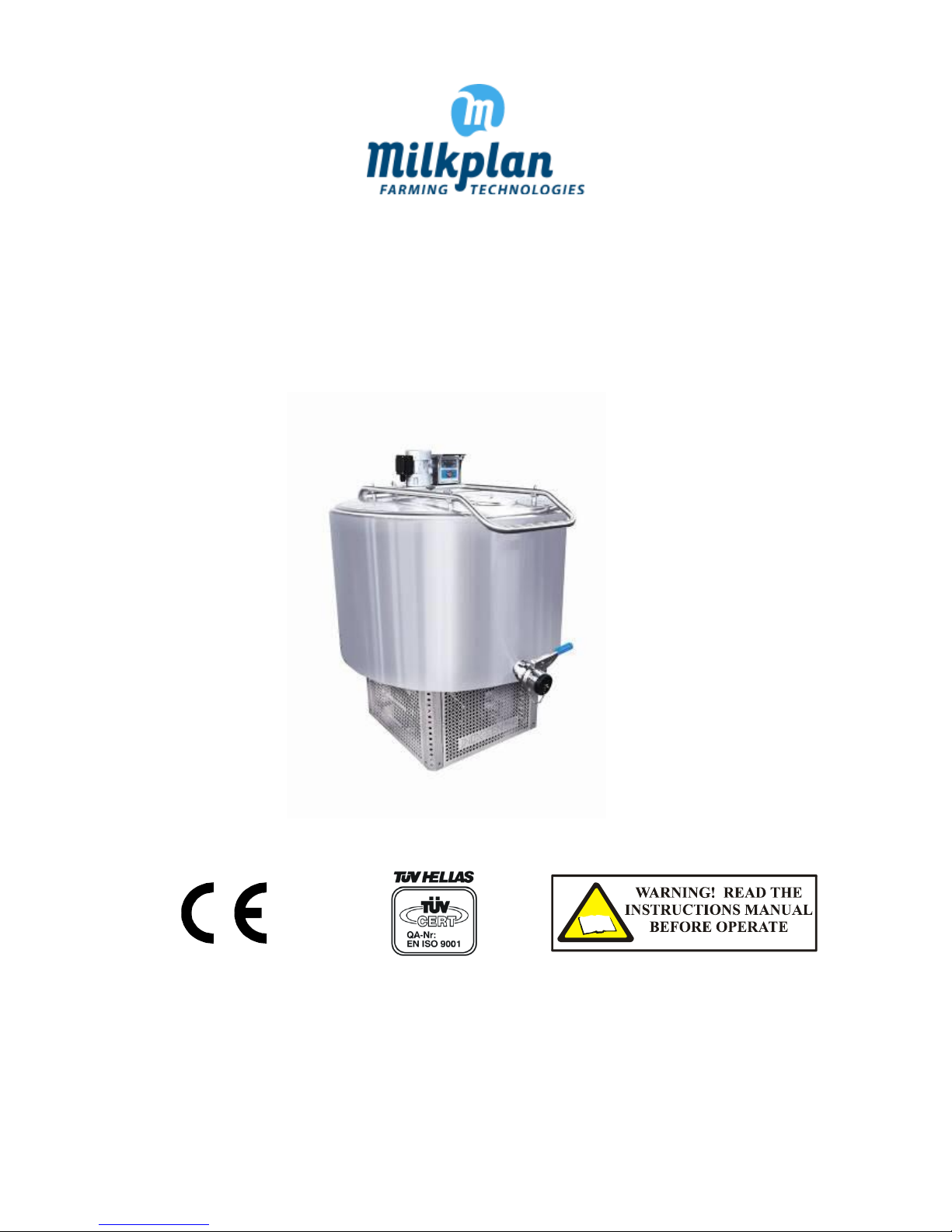
OPEN TYPE MILK COOLING TANK
IC 50 – IC 300
INSTRUCTION MANUAL FOR SAFE AND EFFICIENT USE
MILKPLAN A.E. ΗΜΕΡΙΔΗΣ - ΜΑΚΡΟΠΟΥΛΟΣ
EΞΟΠΛΙΣΜΟΙ ΒΙΟΜΗΧΑΝΙΩΝ ΓΑΛΑΚΤΟΣ & ΚΤΗΝΟΤΡΟΦΙΚΩΝ
ΜΟΝΑΔΩΝ Α.Ε.
3ΟΧΛΜ. ΛΑΓΚΑΔΑ – ΚΟΛΧΙΚΟΥ, ΘΕΣ/ΝΙΚΗ
Τ.Κ. 57200, Τ.Θ. 212
ΤΗΛ/FAX: +30 23940 20400
www.milkplan.com
MILKPLAN S.A.
IMERIDIS - MAKROPOULOS
DAIRY AND FARMING EQUIPMENT S.A.
3rd KM LAGADAS - KOLHIKO NAT. ROAD GR 572
00, P.O.BOX 212
TEL/FAX: +30 23940 20400
www.milkplan.com
30120

2
CONTENT
1. INTRODUCTION...............................................................................................................................................................2
2. SAFETY RULES AND GENERAL INSTRUCTIONS .................................................................................................................3
3. PRODUCT INTRODUCTION ..............................................................................................................................................3
4. LABELING ........................................................................................................................................................................4
5. INSTALLATION INSTRUCTIONS ........................................................................................................................................5
5.1 INSTALLATION PLACEMENT ............................................................................................................................................... 5
5.2 MILK COOLING TANK LEVELLING ........................................................................................................................................ 5
5.3 ELECTRICAL CONNECTIONS................................................................................................................................................. 5
6. OPERATION PRINCIPLE....................................................................................................................................................6
7. DESCRIPTION ..................................................................................................................................................................6
8. TECHNICAL SPECIFICATIONS............................................................................................................................................7
8.1 GENERAL ............................................................................................................................................................................. 7
8.2 POWER SPECIFICATIONS ..................................................................................................................................................... 7
8.3 MAIN DIMENSIONS............................................................................................................................................................. 8
8.4 CONDITIONS OF MEASUREMENT FOR THE PERFORMANCE OF THE REFRIGERATING UNIT............................................... 8
9. USING THE TANK.............................................................................................................................................................9
9.1 COOLING CONTROLLER....................................................................................................................................................... 9
9.2 ADJUSTING THE BASIC PARAMETER VALUES OF THE XR80CX ............................................................................................ 9
10. MILK COOLING TANK MAINTENANCE - CLEANING ........................................................................................................12
10.1 CLEANING THE TANK....................................................................................................................................................... 12
10.2 CLEANING THE CONDENSER OF REFRIGERATING UNIT .................................................................................................. 12
11. SAFETY MEASURES........................................................................................................................................................13
12. MALFUNCTION AND TROUBLESHOOTING.....................................................................................................................14
13. MECHANICAL DRAWINGS (MACHINE PARTS)................................................................................................................16
14. ELECTRICAL DATA AND DRAWINGS...............................................................................................................................17
14.1 ELECTRIC LINE OPTIONS TABLE ....................................................................................................................................... 17
14.2 ELECTRICAL DRAWINGS .................................................................................................................................................. 18
15. WARRANTY CERTIFICATE ..............................................................................................................................................24
16. NOTES...........................................................................................................................................................................26
17. TECHNICAL SUPPORT ....................................................................................................................................................27
Copyright © 2012 MILKPLAN ...............................................................................................................................................27
3
1. PRODUCT INTRODUCTION
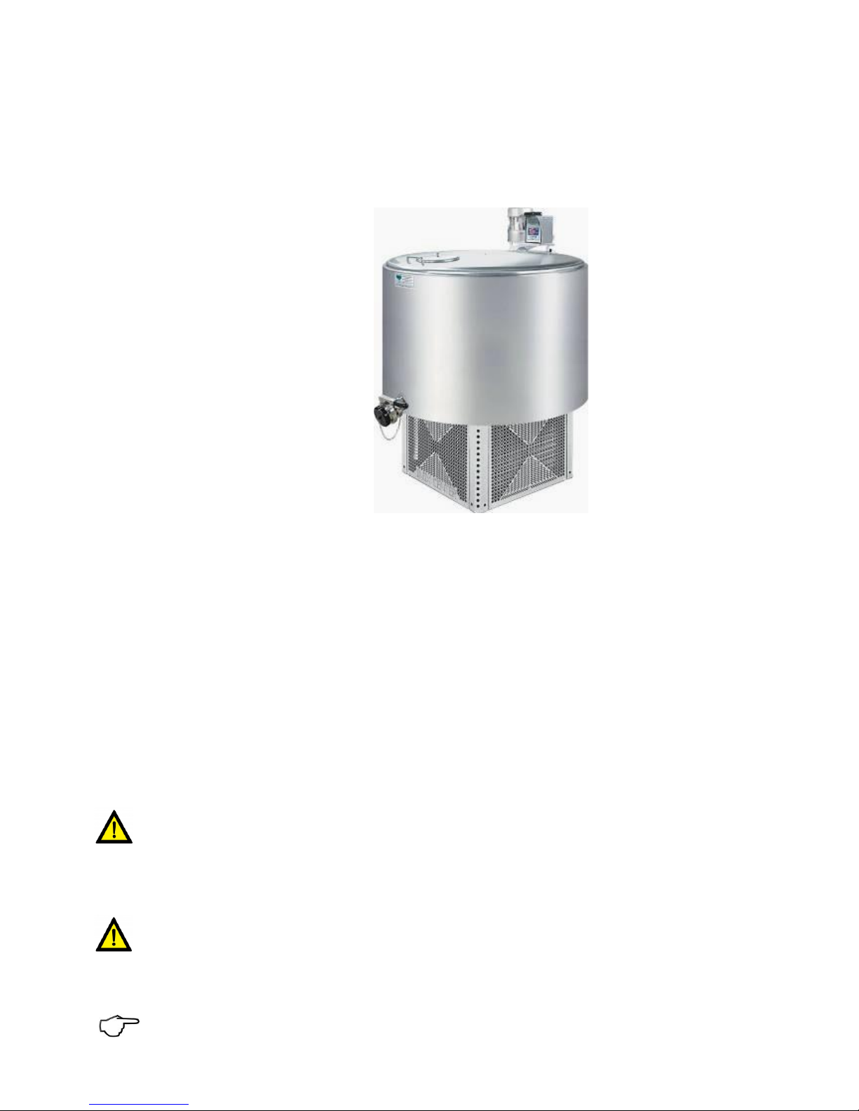
Your new MILKPLAN milk cooling tank is designed and manufactured by experts in cooling and conserving milk. It is constructed
using the most modern equipment and technology.
Milk refrigeration is accomplished via a stainless steel straight direct expansion evaporator plate, operated in an economical
way and for maximum performance.
The materials used for the construction of the milk cooling tank are of the highest quality in the European Trade Market and
guarantee a long life and reliable operation.
The controller is an Italian Dixell type with an error of less than 1%.
The agitator motor is made in France by Sirem and its power is 90W/230V/30 rpm (in types of 50 ~ 1200 lit).
The closed type condensing unit is made by L’Unite Hermetique, a trusted name in the European compressor market.
The base of the milk cooling tank has been designed for safe operation and easy maintenance. The refrigerating unit and the
control panel are well protected from external environmental conditions and from small animals and rodents that could enter
the refrigerating unit and cause damage.
2. SAFETY RULES AND GENERAL INSTRUCTIONS
During the design and construction of this machine everything has been done to make your job more efficient and secure.
However, caution is of great importance. Prevention is better than regulation.
This machine is designed and constructed according to the Annex V directive 98/37 EU and the ΕΝ 292-1, ΕΝ 292-2, ΕΝ 294,
ΕΝ 349, ΕΝ 418, ΕΝ 1672-1, ΕΝ 1672-2, ΕΝ 60204-1standards.
The exclamation point within an equilateral triangle is intended to alert the user of the presence of important oper-
ation and maintenance (service) instructions in this manual. Upon seeing you are highly advised to pay attention to
the warning and be careful of any accidents.
After this symbol an instruction follows.
3. PRODUCT INTRODUCTION
ATTENTION! This manual is an integral part of the milk cooling tank and must be kept nearby in a safe place. This
should be made known to all users. Do not expose this manual to rain or moisture.
Read this manual regardless of your previous experience. A few moments of careful reading will save time and will prevent
many problems. Carefully read the instructions before the start-up of the machine, normal use, maintenance or other functions
on the machine, paying close attention to the following orders and warnings.
Place warning stickers on the machine and replace immediately if they have been lost or are not readable.
4
In order to prevent or reduce risk of accident, the machine should only be operated by adequately trained and
responsible staff. Untrained users should never operate the machine.
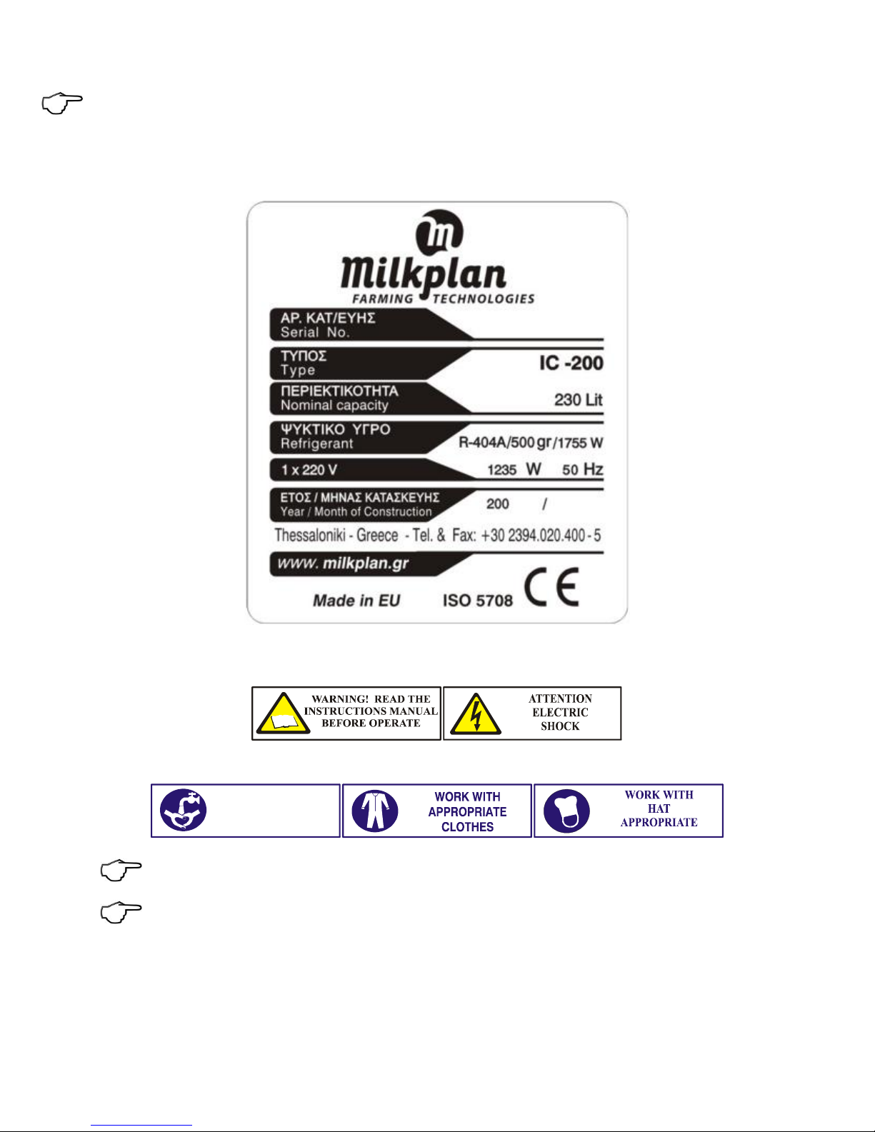
4. LABELING
The manufacturer’s label should be visible at all times as it contains essential information about the manufacturer (address,
phone number, fax) and information for the proper installation of the machine (the model, serial number, year of manufacture,
refrigeration capacity in Watt, electrical power in Watt , voltage, refrigerant type and quantity ) and the CE mark.
WARNING LABELS
The warning labels are to inform the operator of the machine or the equipment and about the remaining risks despite all the
measures adopted.
Due to the nature of the tank contents, strict hygiene rules apply. The following labels should be placed where all employees
can see them.
The inscriptions (warning labels) should be affixed in a visible, easily legible and non-removable spot on the machine
or on to a data plate attached to the machine in such a way that it cannot be removed or become illegible during
the lifetime of the machine in the normal working environment.
Keep labels clean and replace them immediately when they become detached or damaged.
WASH YOUR
HANDS
5
5. INSTALLATION INSTRUCTIONS
5.1 INSTALLATION AND PLACEMENT
The milk cooling tank can be installed indoors or outdoors. It is very important for the milk cooling tank to be installed in a
well-ventilated place with a water supply.
If the tank is to be installed indoors, make sure that the location has sufficient ventilation. Place the tank such that its condenser
lies near an opening in order to allow waste heat to be efficiently discarded.
If the tank is to be installed outdoors, it must be placed under a roof so that it cannot be affected by weather conditions (rain,
snow, etc).
It is also suggested to place the milk cooling tank on a flat concrete surface. Placing the tank on a flexible or deformable surface
can result in inaccurate measurements.
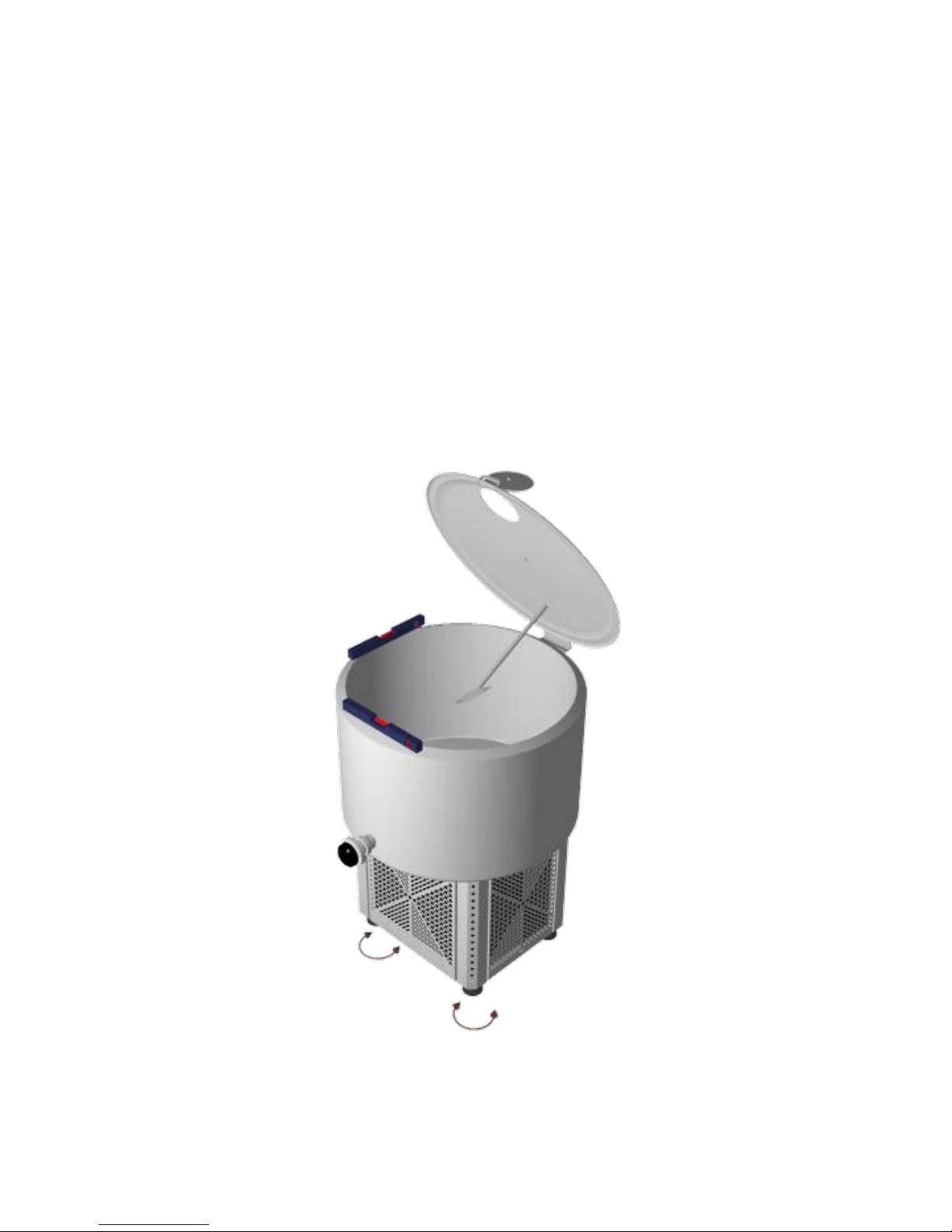
5.2 MILK COOLING TANK LEVELLING
Level the milk cooling tank using a hand spirit level. Open the lid of the tank and place the spirit level on the extremity of the
edge of the tank, as shown in the picture below.
Adjust the footings at the base of the tank until it is successfully leveled in both axes.
It is very important to precisely level the tank so that the volume measurements can be accurate
5.3 ELECTRICAL CONNECTIONS
An authorized electrician must complete or verify the electrical installation before placement of the milk cooling tank.
Tanks can be supplied with a variety of voltage and phase specifications. North American tanks are usually designed to operate
on single phase, 120 Volt, 60 Hz power. Other voltages and phases are available. Each tank is equipped with a label indicating
the proper voltage, current, frequency, and phase requirements.
This manual suits for next models
3
Table of contents


