Millipore Sigma Scepter 3.0 User manual

The life science business of Merck operates
as MilliporeSigma in the U.S. and Canada.
The life science business of
Merck KGaA, Darmstadt, Germany
operates as MilliporeSigma
in the US and Canada.
SigmaAldrich.com
User Guide
Scepter™ 3.0
Handheld
Automated
Cell Counter
PHCC30000

00110230w Rev 10/20 2 of 24
Introduction
The Scepter™ 3.0 Handheld Automated Cell Counter
(“Scepter™ 3.0”) provides a fast and convenient method
for counting cells or particles using a disposable sensor.
Using the Coulter Principle, the Scepter™ 3.0 does all the
work and rapidly delivers accurate and reliable cell counts.
The Scepter™ 3.0 quantifies cells based on size and
discriminates larger cells from smaller debris, unlike
vision-based techniques, which rely on object recognition
software and cannot reliably detect small cells.
A sample of interest is diluted, then acquired using
a precision-engineered, microfluidic Scepter™ 3.0
disposable sensor. In seconds, Scepter™ 3.0 displays cell
concentration, cell diameter or volume measurements,
along with a histogram of cell distribution.
Up to 999 histograms can be stored in the instrument.
The Scepter™ 3.0 has a wireless network interface which
allows you to send histograms and data files to your
Wi-Fi®printer or computer easily. No more cables.
The new Charging Station stores Scepter™ 3.0 out-of-the-
way when not in use,
freeing up valuable hood or lab bench space.
This system is intended for research use only.
Contents
Introduction ....................2
Symbols and Safety Precautions ....3
Parts and Functions ..............4
Features 4
Control Buttons and Screen Icons 4
Battery 5
Installing the Charging Station 6
Getting Started ..................7
Date and Time 7
Bluetooth®Enabled Printer 7
Wi-Fi®Network 8
Gating Method 10
Display Units 10
Sensors ......................11
Technology 11
Attach the Sensor 11
Cell Counting ..................12
Cell, Bead, and Particle Suspensions 12
Scepter™ 3.0 Test Beads 12
Counting Process 13
Histogram Explorer .............13
Go to Home 13
Edit Analysis 14
Switch to Volume / Diameter 14
Scale Y-Axis Count 14
Exporting Data 15
Reviewing Saved Data 16
Deleting Saved Data 16
Printing ......................17
Help Screens...................17
Tutorials 17
DNS, IP, Mac®Address 17
Firmware Updates ..............17
Storage and Maintenance .........18
Storage 18
Cleaning/Sanitizing 18
Maintenance 18
Troubleshooting ................18
Error Messages 19
Notice 21
Specifications .................22
Contact Information 22
Technical Assistance 22
Standard Warranty 22
Product Ordering ...............23
Global Registration
Marks of Conformity .............24

00110230w Rev 10/20 3 of 24
Symbols and Safety Precautions
This system is intended for research use. Go to SigmaAldrich.com/techservice for assistance.
IT IS IMPORTANT TO READ THESE INSTRUCTIONS BEFORE USING THIS INSTRUMENT.
Y
• Please read these safety instructions and user manual carefully before using the cell counter and/or any accessory
supplied with this product.
• Keep these instructions for future reference.
• If there is any contradiction between the information in the manual and the information in this notice, the information in
this notice takes precedence.
• The protection provided by this equipment may be compromised if it is used incorrectly.
• Obey the instructions that are given to you. Do not perform any work on the inside of the instrument.
YThis symbol indicates that there is a component inside the cell counter that might represent a particular hazard
(refer to the operating manual) (HAZARD).
For Global Registration Marks of Conformity, p.24.
CAffixed in accordance with the most recent European Council Directives which apply to this instrument.
Please refer to the Declaration of Conformity for further detail.
Federal Communications Commission (FCC) conformity marking TFB-1003.
This symbol represents the products compliance to Chinese RoHS. For more information on RoHS compliance
please see the products Declaration Of Conformity.
This product has been evaluated by an OSHA certified Nationally Recognized Testing laboratory (NRTL).
Y WARNINGS
• To avoid danger of electric shock, do not install the instrument in an area with a high humidity level, such as a greenhouse or an incubator.
Refer to
Operating Environmental Conditions, p.22
.
• Do not touch the charger station and plug with wet hands.
• To avoid potential shock hazard, choose the correct plug configuration and make sure that the USB cable/power adapter
is plugged securely into a properly grounded AC power outlet.
• Always ensure that the power supply input voltage matches the voltage available in your location.
• Do not use with flammable or explosive liquids.
• Do not immerse instrument body in liquid, or allow liquid to enter any part of the instrument.
• Do not expose instrument to vibrations. Vibrations may cause instrument malfunction or damage.
• Do not autoclave or expose to high temperature.
• To avoid damage to internal electronic components, do not spray instrument with sanitizing agents. Refer to Cleaning/Sanitizing,
p.18 for sanitizing information.
• Use only authorized accessories (Charging Station).
• If the instrument is broken or dropped, Do not try to disassemble the instrument. Go to SigmaAldrich.com/techservice for assistance.
BATTERIES
Battery is not user accessible or user replaceable. For more information, go to SigmaAldrich.com/techservice.Do not use instrument in a humid
and/or corrosive environment.
• Do not disassemble, pierce or modify the batteries or subject them to unnecessary shocks that would risk damaging them.
• Do not leave near or in direct contact with a heat source (risk of leakage and/or explosion which may cause injuries and/or damage).
• In the event of leakage and direct contact with the fluid, rinse the exposed area with plenty of water and seek medical
advice immediately.
• Do not put the batteries in your mouth. If swallowed, seek medical advice or contact the nearest poison control center immediately.
THE LITHIUM-ION BATTERY OF YOUR INSTRUMENT CONTAINS SUBSTANCES THAT MUST BE RECYCLED. DO NOT DISCARD WITH
COMMON SOLID WASTE AT END OF LIFE. PLEASE DISPOSE OF IT IN A RECYCLING BIN SUITABLE FOR THIS TYPE OF PRODUCT.
SEGREGATE WITH OTHER WASTE ELECTRICAL AND ELECTRONIC EQUIPMENT (WEEE) IN THE EUROPEAN UNION, PLEASE VISIT
SigmaAldrich.com/weee.
SYSTEM DISMANTLING – WEEE directive
In accordance with European Union directive on the management of waste electrical and electronic equipment (WEEE),
this product must not be disposed of in unsorted municipal waste at the end of its life. It must be taken to a collection
and recycling center. For further information, go to
SigmaAldrich.com/weee.
ANTENNA
Unauthorized modification of the built-in antenna or use of unauthorized accessories might damage the system and render it
non-compliant with directives such as the EU RED directive and FCC regulations. This instrument complies with part 15 of the
FCC Rules. Operation is subject to the following two conditions: (1) This instrument may not cause harmful interference, and
(2) this instrument must accept any interference received, including interference that may cause undesired operation.
00110230w Rev 10/20 4 of 24
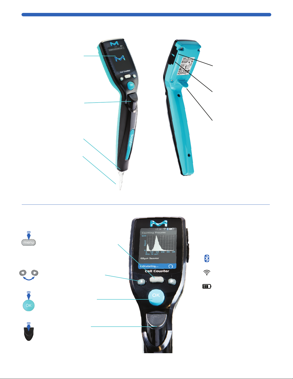
Parts and Functions
Features
Sensor Port
Insert sensor
Disposable Sensor
• Required for
sampling cells
• 40 µm or 60 µm
• See Attach the Sensor,
p.10 before inserting
MENU Button
• TURN ON / OFF: press and hold
• Return to the menu screen
• Abort any process immediately
ARROW Buttons
• Scroll through menus:
right = down, left = up
• Scroll to next/previous histogram
OK Button
• Accept selected fields
• Advance to continue
EJECT Button
Ejects the sensor
Tech Service Port
For Service use only
USB Port
Connects instrument to
USB thumb drive
Ergonomic Hook
• Allows comfortable
handling of the
instrument
• Secures the instrument
to charger
Control Buttons and Screen Icons
Display Screen
• Displays all information
needed for operation
• Displays histograms with
with cell concentration,
and diameter or volume
Bluetooth®icon
connected if visible
Wi-Fi®icon
connected if visible
Battery life indicator icon
Continue Arrow appears
in the lower right corner
of the screen, only when
there are additional
menu options. Scroll to
see more options
Eject Button
Ejects Sensor
V
Instrument Schematic
00110230w Rev 10/20 5 of 24
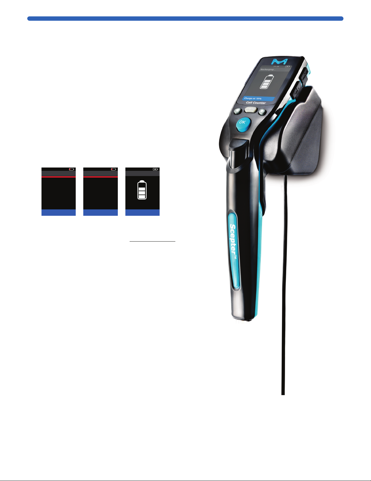
Battery
The Scepter™ 3.0 is equipped with an internal 3.7 V lithium
ion battery that recharges in the Charging Station. Install
the Charging Station (see page 6) and plug into AC wall
outlet. Place Scepter™ 3.0 onto the Charging Station.
REGHARGING will be displayed. Allow battery to charge
for 3 hours prior to use.
The overall battery life is approximately 2 to 5 years,
depending on use.
When not in use, the instrument should be stored on the
Charging Station so that the battery maintains charge. It
is not necessary to deplete the battery before recharging
Scepter™ 3.0. For optimal performance, operate when
battery levels are greater than 20%.
If “WARNING - Low Battery” appears on the display screen,
stop using the instrument and charge the battery.
01-Feb-18 14:16
Attention!
Press OK to continue
Battery needs
recharging!
Please recharge
the instrument!
01-Feb-18 14:16
Attention!
Please recharge!
Battery is
critically low!
System is
powering down.
01-Feb-18 14:16
Recharging...
Charge at 20%
If the battery is completely dead and does not show the
Recharging screen when placed in the Charging Station,
the following steps must be followed to start charging
the Scepter™ 3.0 battery:
1. Place Scepter™ 3.0 into the Charging Station.
2. While on the station, press and hold the MENU button
for several seconds, until the the vibrant M appears.
3. Release the MENU button and allow Scepter™ 3.0
to remain in the charger for approximately 3 hours
or until fully charged.
CAUTION: To prevent battery damage, use ONLY the
specified Charging Station (Cat. No. PHCC3CHARG). Charging
cables from previous Scepter™ products are not suitable for
charging this instrument.
DO NOT try to use the instrument while on the Charging
Station. The Scepter™ 3.0 Handheld Automated Cell Counter
is designed to operate on battery power only. Electrical
interference with sensor function may produce
inaccurate readings.
WARNING: Lithium-ion batteries can easily rupture, ignite, or explode
when exposed to high temperatures, or direct sunlight. Short-circuiting
a Lithium-ion battery can also cause it to ignite or explode. ONLY use
Charging Station (Cat. No. PHCC3CHARG). Never open the instrument
or battery’s casing. Contact Technical Service for more information.
Battery is not accessible or replaceable by the user.
Plug into
electrical
wall outlet

00110230w Rev 10/20 6 of 24
Mounting
Plate Tabs
Mounting
Tab Recesses
Magnets
Installing the Charging Station
Scepter™ 3.0 can be placed on the benchtop horizontally or
vertically wall-mounted, within 5 feet (1.5 meters) from an
electrical outlet. The mounting kit is required to mount the
Charging Station. See Product Ordering, p.23 for accessory
and kit purchasing options. Figure 1 shows
the wall area required.
For mounting on drywall, wood or similar:
1. Use screws and anchors.
2. Use 0.25 inch diameter drillbit for anchor holes.
Seat anchors gently with a hammer.
3. Install screw in top anchor first, hook plate into place
using screw keyhole. Install 2nd screw tight, then tighten
1st screw. (Continue to steps 4 and 5 below.)
For mounting on glass, metal or smooth stickable surface:
1. Use double-sided mounting tape.
2. Remove tape liner from one side of tape and
affix to back of mounting plate as shown below.
3. Remove remaining tape liner and press firmly
onto glass, metal or smooth stickable surface.
4. Position the Charging Station with mounting plate
bottom tabs seated in mounting tab recesses. The
mounting plate magnets hold the Charging Station in place.
NOTE: Do not use the magnets without mounting plate.
Doing so may cause the charger to rotate slightly,
compromizing the charging contact.
Figure 1: Wall area required for mounting
Charging Station.
Front
Facing
Screws
Wall Anchors
Front of
Mounting
Plate
Front
Facing
Tape
Back of
Mounting
Plate
Image shown with
both screws and
mounting tape.
Do not use both in
actual application.
5. Hang the Scepter™ 3.0 on the
Charging Station. See Battery, p.5
before use.
3.125 in.
(82.5 mm)
1.56 in.
(39.6 mm)
2.5 in.
(63.5 mm)
1.5 in.
(88.1 mm)
7 in.
(177.8 mm)
11 in.
(279.4 mm)
Clearance for
Instrument

00110230w Rev 10/20 7 of 24
Getting Started
To turn on, make sure Scepter™ 3.0 is fully charged and press/hold the MENU button. Release when
the vibrant M appears on screen. For setup, the sensor is not needed, press MENU to advance to
Settings. Use the ARROW keys to scroll to Settings, press OK. It is recommended to set up all
aspects of Scepter™ 3.0 before use.
Date and Time
The date and time are used in the file name when the histogram is uploaded to a computer.
SET UP DATE
01-Feb-18 14:16
Settings
Back
Date & Time
Bluetooth
Wifi
Gating Method
Display Units
<
1. From the Menu screen
scroll to Settings, press
the OK button.
2. Scroll to Date & Time,
press the OK button.
3. Select Edit Date, and
press the OK button.
4. Scroll to enter the desired
day/month/year. Press
the OK button after
each selection.
01-Feb-18 14:16
Date & Time
Back
Edit Date
Edit Time
<
Press OK to accept
01-Feb-18 14:16
Edit Date
Day
Month
Year
<23 >
Feb
18
Press OK to accept
01-Feb-18 14:16
Edit Date
Day
Month
Year
23
<Feb >
18
Press OK to accept
01-Feb-18 14:16
Edit Date
Day
Month
Year
23
Feb
<18 >
Press OK to accept
SET UP TIME
01-Feb-18 14:16
Date & Time
Back
Edit Date
Edit Time
<
Press OK to accept
01-Feb-18 14:16
Edit Time
Hours
Minutes
Seconds
<14 >
16
34
Press OK to accept
01-Feb-18 14:16
Edit Time
Hours
Minutes
Seconds
14
<16 >
34
Press OK to accept
01-Feb-18 14:16
Edit Time
Hours
Minutes
Seconds
14
16
<34 >
Press OK to accept
1. Scroll to Edit Time, and
press the OK button.
2. Scroll to enter the desired
hour/minute/seconds.
Press the OK button after
each selection.
3. Press the MENU button to
return to Menu Screen.
Bluetooth®Enabled Printer
From the Settings Menu, scroll to Bluetooth and press the OK button.
1. Scroll to Turn On (or Off,
and press the OK button. The
display shows Searching for
printers. All the printers within
range will be displayed.
2. Using the ARROW buttons,
scroll to select the desired
printer, press the OK button
to start the connection.
Wait for confirmation screen.
3. Press the OK button to return
to Settings.
01-Feb-18 14:16
Menu
Home<
Histograms
Settings
Help
01-Feb-18 14:16
Settings
Back
Date & Time
Bluetooth
Wifi
Gating Method
Display Units
<
01-Feb-18 14:16
Bluetooth
Back
Turn On
<
Press OK to accept
01-Feb-18 14:16
Bluetooth
Searching...
Searching for
printers...
01-Feb-18 14:16
Bluetooth Printers
Back
Front Office Printer
Lab Printer
Mgr Printer
<
Press OK to accept
01-Feb-18 14:16
Bluetooth
Connecting...
Connecting to
printer:
Lab Printer
01-Feb-18 14:16
Bluetooth
Press OK to continue
Connection was
successful to
printer...
Lab Printer
The only Bluetooth®printers supported by Scepter™ 3.0 are Cannon®IVY, Polaroid ZIP™ Instant
Photoprinter, and HP®Sprocket Photo Printer. No other printers currently supported.
00110230w Rev 10/20 8 of 24
TIP
Having Trouble?
See Troubleshooting
Wi-Fi®Network
Materials required to link Scepter™ 3.0 to your Wi-Fi®network:
• Wireless Network broadcasting at 2.4 Ghz
• USB thumb drive formatted to FAT32 (FAT32 is a common filesystem format compatible
with Windows, Mac®OS X, and Linux)
• PC, Mac®or UNIX®Computer with text editing program (Microsoft®Windows®Notepad, TexEd or similar)
• Scepter™ 3.0 Instrument
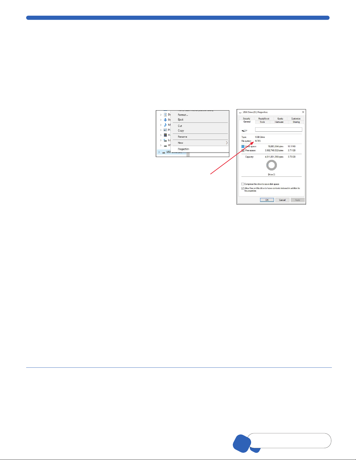
USB Thumb Drive Formatting
Scepter™ 3.0 is compatible with USB thumb drives formated to FAT32. No other format is compatible.
To check your USB thumb drive format,
insert it into a USB port on your computer.
From your computer, open File Explorer or
similar, and locate the USB thumb drive.
Right click on the USB thumb drive icon and
select Properties.
• If the File system is identified as “FAT32”,
no formatting is needed. Continue to
Creating a Wi-Fi®Configuration File.
NOTE: This view will also show how
much space is available on your USB
thumb drive.
• If the File system is identified as any
other format, the following steps should
be followed.
NOTE: Formatting a USB thumb drive
will erase all contents of the drive. Please
back up any data you wish to retain prior
to formatting.
1. After identifying the existing format
on the USB thumb drive, right click
again. Select Format.
2. The Formatting dialog window will
open. Select FAT32. Select the Quick
Format option and press enter.
NOTE: Removing the USB thumb
drive during formating may
irreparably damage the
USB thumb drive.
3. Once formating has completed your
computer should indicate Format
Complete. Continue to Creating a
Wi-Fi®Configuration File.
This is the incorrect
format. Please follow
steps to format this
drive to FAT32.

00110230w Rev 10/20 9 of 24
TIP
Having Trouble?
See Troubleshooting
Creating a Wi-Fi®Configuration File
A “Wi-Fi®configuration file” is needed for set up or to change Wi-Fi®networks.
On a computer, open up the text editing program. The examples below are using Microsoft®Windows®Notepad.
1. Type following parameters with no spaces, as
shown below: Replace exampleNetwork with the
name of the desired wireless network. Replace
ssidPassword with the password to the desired
wireless network:
Name=exampleNetwork
Passphrase=ssidPassword
Type=wifi
Favorite=true
AutoConnect=true
2. Save and name the file the same name of the
desired wireless network with “.config” file
extension.
exampleNetwork.config
Note: If you’re using Notepad included with
Microsoft®Windows® software, it will try to save
the file as a .txt file by default. For this file to
be saved properly, ensure it is being saved as
All Files type like the example (right).
3. Drag the file from the computer onto the USB
thumb drive. Once the file has loaded, remove
the USB thumb drive from the computer port.
Connect to Wi-Fi®Network
1. From the Main Menu, select Settings and press the OK button. Select Wi-Fi®and press the OK button.
Insert the USB thumb drive containing the credential file into the Scepter™ 3.0 USB port.
2. Scroll to Turn On,
and press the OK
button. Scroll to Show
Networks, press the OK
button. The instrument
will begin Searching for
networks....
3. The instrument will list
networks within range.
Scroll to the desired
network and press the OK
button. When connection
is complete, the screen
will confirm successful
connection.
4. Press the OK button to
return to Settings Menu.
5. Remove USB thumb
drive.
01-Feb-18 14:16
Wifi
Back
Turn On
<
Press OK to accept
01-Feb-18 14:16
Wifi
Back
Turn Off
Show Networks
<
Press OK to accept
01-Feb-18 14:16
Wifi
Searching...
Searching for
networks...
01-Feb-18 14:16
Wifi Networks
Back
Guest
MP123
Sizzafritz
<
Press OK to accept
01-Feb-18 14:16
Wifi
Connecting...
Connecting to
network:
MP123
01-Feb-18 14:16
Wifi
Press OK to continue
Connection was
successful to
network...
MP123

00110230w Rev 10/20 10 of 24
TIP
Pressing the Menu button
will end any procedure
Gating Method
There are two options for setting the default gates (upper and lower diameter or volume limits of the histogram)
prior to counting. One option is to choose “Use Last” and the other is “Auto” which automatically sets the gates
based on the histogram profile. The gates can also be changed manually after the count has been performed.
Manual gating is recommended when using the 40 µm sensor or when optimizing counting parameters
for a new sample.
1. From the Settings menu, select
Gating Method and press the
OK button.
2. Scroll to select desired setting,
and press the OK button.
Auto
This setting will set the gates
automatically based on the
histogram profile. Use this setting
when sampling Scepter™ 3.0
Test Beads.
Use Last
This setting maintains on
whatever gating parameters were
last set by the user, either during
a count or during post count
data management.
01-Feb-18 14:16
Menu
Home<
Histograms
Settings
Help
01-Feb-18 14:16
Settings
Back
Date & Time
Bluetooth
Wifi
Gating Method
Display Units
<
01-Feb-18 14:16
Gating Method
Back
Auto
Use Last
<
Press OK to accept
01-Feb-18 14:16
Gating Method
Back
Auto
Use Last
<
Press OK to accept
Display Units
Set the histogram default display to either cell (or particle) volume in picoliters (pL) or in cell (or particle)
diameter in microns (µm). Individual histograms can be switched in the Histogram Explorer, p.13.
Use the ARROW buttons to scroll
through options.
1. Scroll to Histograms, press the
OK button.
2. Select Display Units and press
the OK button.
01-Feb-18 14:16
Menu
Home<
Histograms
Settings
Help
01-Feb-18 14:16
Settings
Back
Date & Time
Bluetooth
Wifi
Gating Method
Display Units
<
3. Scroll to choose Diameter (μm)
or Volume (pL).
Note: Scepter™ 3.0 shows
your last choice first.
4. Press the OK button to return
to the Settings menu.
01-Feb-18 14:16
Display Units
Back
Diameter (µm)
Volume (pL)
<
Press OK to accept

00110230w Rev 10/20 11 of 24
TIP
Pressing the Arrow buttons
to scroll through options
Sensors
Technology
The Scepter™ 3.0 Sensors are microfluidic channels designed to replicate the
Coulter Principle. Cell suspension is drawn into the reservoir channel and through
the aperture sensing region. Increase in resistance causes an increase in voltage
proportional to cell size (diameter). For each passing cell, voltage changes are
recorded providing sample count and concentration. The sample is contained in
the sensor and disposed of after each sample reading.
The Scepter™ 3.0 can be used with either a 60 μm or a 40 μm sensor.
Depending on the sample being counted, some user optimization may be
required relating to cell size and concentration.
Sensor
size Operating Range
Sensor X-Axis
Scale (µm)
Working Diameter
Range (µm)
40 µm 50,000–1,500,000 cells/mL 4-20 5-15
60 µm 10,000–500,000 cells/mL 6-36 8-25
Sensors are not reusable. Attempting to reuse the sensor will result in an error
message on the instrument. However, an unused sensor may be removed from
the Scepter™ 3.0 and reinserted. Only Scepter™ 3.0 Sensors will fit into the
Scepter™ 3.0 instrument. Do not use sensor if visibly damaged.
Attach the Sensor
1. When the Scepter™ 3.0 is powered on, it
will show Attach the Sensor to begin.
2. Holding the sensor with the sensor size
number facing you, and the Scepter™3.0
with the screen facing you, firmly insert the
sensor into the sensor port, The sensor stop
wings prevent over insertion.
IMPORTANT: To avoid severe instrument
damage and costly repair, orient the sensor
correctly before inserting it into the attachment
port. Extreme force is not required to insert
the sensor. Check the orientation of the sensor
if having difficulty.
01-Feb-18 14:16
Home
Attach the Sensor
to begin...
3. When the sensor is properly inserted,
Scepter™ 3.0 will begin Characterizing
the Sensor.
4. The screen will indicate
Submerge the Sensor...then press OK.
You are ready to begin Cell Counting.
01-Feb-18 14:16
Counting Process
Please wait...
Characterizing
the Sensor
60µm Sensor
01-Feb-18 14:16
Counting Process
Ready
Submerge
the Sensor...
then press OK
60µm Sensor
Sensor Size
“40“ or “60” must
face forward before
inserting
Confirm the device
and sensor size marking
are facing forward
Sensor
Stop Wings prevent
over-inserting
sensor into
Scepter™ 3.0
Reservior
channel
Gently but firmly,
push sensor into
sensor port until
the Sensor Stop
Wings meet
the device
Precise Coulter
technology

00110230w Rev 10/20 12 of 24
TIP
Pressing the Menu button
will end any procedure
Cell Counting
• Prepare dilutions in 1.5 mL microcentrifuge tubes. Other tubes may not be able to accommodate
the width of the sensor, or provide sufficient sample depth for the instrument to function properly.
• Use a diluting solution compatible with the characteristics of cells. The diluting solution used should not
cause changes in the cell size and should have sufficient conductivity to enable operation of the instrument.
Recommended diluting solutions include:
• Dulbecco’s Phosphate buffered saline, D-PBS, with or without calcium and magnesium
(Embryomax®D-PBS Cat. No. BSS-1006)
• 10% Fetal Bovine Serum, FBS (Embryomax®serum Cat. No. ES-009-B) in D-PBS
• Dulbecco’s Modified Eagle’s Medium, DMEM (Embryomax®solution DMEM Cat. No. SLM-220B)
• Complete media (10% FBS in DMEM), and diluted in D-PBS
• 1% dimethyl sulfoxide (DMSO) cell freezing media (Hybri-Max™ DMSO Cat. No. D2650) in D-PBS
• Cell detachment solution (Accutase®Cat. No. SCR005)
• Water, hypotonic, or hypertonic solutions are not acceptable diluting solutions.
Note: Detergents may interfere with counting; 10% DMSO is not an acceptable diluting solution, but
1% DMSO may be used. Serum-enriched media >10% may also interfere with counting. Dilute samples
with D-PBS, diluted serum in D-PBS (≤10% FBS), DMEM basal medium, DMEM-based complete medium
with ≤10% FBS (undilute or diluted in D-PBS), and Accutase®cell detachment solution.
Some suspensions may require a pre-filtration step to remove larger than rated cell clumps, particle populations,
or debris that would clog the sensor’s aperture. A Steriflip®filter with 20 µm nylon net is recommend
(use low vacuum ≤5”Hg).
Cell, Bead, and Particle Suspensions
Materials Required
◊ Cell sample, Scepter™ 3.0 Test Beads (Cat. No. PHCC3BEADS), or particle suspensions
Note: Some particle suspensions may have a broad diameter range. Debris and/or particles
near or over sensor rating may clog aperture resulting in an Aperture block error, see p. 20.
◊ 1.5 mL microcentrifuge tubes
◊ Scepter™ 3.0 Sensors
• The sample volume must be at least 100 μL to draw into the sensor’s microfluidic channels.
• Perform Installing the Sensor steps prior to proceeding.
In a 1.5 mL microcentrifuge tube, dilute the single-cell suspension with an appropriate diluting solution
so the cell concentration is within the operating range of the instrument for the sensor being used. The
appropriate dilution will depend on cell type, seeding density, and suspension volume. The volume required
for an accurate count is 100 µL.
Sensor size Operating Range
Sensor X-Axis
Scale (µm)
Working Diameter
Range (µm)
40 µm 50,000–1,500,000 cells/mL 4-20 5-15
60 µm 10,000–500,000 cells/mL 6-36 8-25
Scepter™ 3.0 Test Beads
To ensure proper system operation, the Scepter™ 3.0 can be tested periodically with Scepter™ 3.0 Test Beads.
The beads can be used to test the system when first received, as well as for practice and troubleshooting. Refer
to the Scepter™ 3.0 Test Bead container label for expected bead concentration and diameter. The procedure
for testing with Scepter™ 3.0 Test Beads and counting cells is the same, except that the beads are ready to
use and require no dilution. The Scepter™ 3.0 Test Beads are compatible with both 40 and 60 μm sensors.
• Allow Scepter™ 3.0 Test Beads to come to room temperature before use.
• Mix Scepter™ 3.0 Test Beads gently by shaking bead vial for 30 seconds. If using vortex, mix at low speed.
Excessive mixing can lead to inaccurate counts.

00110230w Rev 10/20 13 of 24
TIP
The continue-arrow in the lower right
screen indicates more menu options V
Counting Process
Perform Attach the Sensor, p.11 before continuing with this section.
1. Immediately after mixing, submerge
the tip of the sensor into the middle of
the sample tube solution and press the
OK button to begin counting. Resting
the sensor against the tube bottom may
result in inaccurate results. It is normal
to hear the pump clicking.
01-Feb-18 14:16
Counting Process
Ready
Submerge
the Sensor...
then press OK
60µm Sensor
01-Feb-18 14:16
Counting Process
Loading Sample...
Keep the Sensor
submerged
60µm Sensor
01-Feb-18 14:16
Counting Process
Counting...
Lift the Sensor
out of the Sample
60µm Sensor
Note: It is important to press the
OK button only after the sensor is
submerged, and keep it submerged as
long as the screen displays Keep Sensor
submerged. Do not to rest your thumb
on the EJECT button during sampling,
as it can cause inaccurate results.
01-Feb-18 14:16
Counting Process
Calculating...
Count
0
900
36
24 3018126
Dia. in µm
60µm Sensor
01-Feb-18 14:16
Counting Process
Saving...
Count
0
900
36
24 3018126
Dia. in µm
60µm Sensor
01-Feb-18 14:16
Counting Process
Eject Sensor to continue
Count
0
900
36
24 3018126
Dia. in µm
Count Complete
2. Scepter™ 3.0 will beep when sample loading is completed and the sensor can be lifted out of the solution.
Pause briey, while Scepter™ 3.0 creates the histogram. Press the EJECT button to eject the sensor into
an appropriate cast o container when directed to do so on the screen. Discard used sensors appropriately.
Scepter™ 3.0 Sensors are not reuseable.
3. When the count is complete, the histogram is automatically created. The concentration and diameter
or volume will be displayed on the screen. Press the OK button to save (up to 999 histograms in the
Scepter™ 3.0 memory), and open the Histogram Explorer. Press the OK button to return to Home screen.
Changing the histogram gating method and other features are done in Histogram Explorer.
Note: Files are automatically named: ScepterID.Sample#.Date_time.png (or .csv).
Note: When using Scepter™ 3.0 Test Beads, set gating to Auto for best results.
Histogram Explorer
Up to 999 histograms can be saved for future review. When the display screen shows Disk Full, the acquired
data can no longer be saved. To continue, histograms must either be deleted or uploaded to a computer.
Note: The counting procedure can still be performed when the disc is full, but histograms and data will
not be saved. To delete histograms, refer to Deleting Saved Data, p.16.
Histogram Explorer can be found
two ways:
From the Main Menu, select
Histograms, and the last saved or
acquired histogram will be shown.
Scroll to see the next histogram.
Press the OK button to select.
01-Feb-18 14:16
Menu
Home<
Histograms
Settings
Help
01-Feb-18 14:16
Histogram
Test 3 03-Dec-17
Count
0
900
36
24 3018126
Dia. in µm
3.342e5
15.682
/mL
µm
Conc.
Dia.
01-Feb-18 14:16
Histogram
Test 2 29-Nov-17
Count
0
900
36
24 3018126
Dia. in µm
3.254e5
15.785
/mL
µm
Conc.
Dia.
01-Feb-18 14:16
Histogram
Back
Go to Home
Edit Analysis
Switch to Volume
Scale Y Axis Count
Export to USB
Print
<
After Counting Process, the histogram will be displayed.
Press the OK button to select. The Histogram Explorer Menu will appear. The blue “continue-arrow”
is in the lower right corner, indicating additional option(s) can be viewed by scrolling down.
Go to Home
Prompts to start new sample count.
01-Feb-18 14:16
Histogram
Back
Go to Home
Edit Analysis
Switch to Volume
Scale Y Axis Count
Export to USB
Print
<
01-Feb-18 14:16
Home
Attach the Sensor
to begin...
EJECT
(( BEEP))
CONTINUE-ARROW

00110230w Rev 10/20 14 of 24
TIP
Pressing the Arrow buttons
to scroll through options
Edit Analysis
1. Select Histogram from the main menu
and scroll to Edit Analysis, press OK.
Low gate will be highlighted and a
flashing red line flanked by red arrows
shows on the histogram. Press the
OK button.
2. Increase or decrease the Low gate
number using the ARROW buttons.
Press the OK button to select. The
low gate will flash red on the
histogram again.
3. Scroll to advance to High Gate,
press the OK button.
4. Adjust the High Gate similarly by
using the ARROW buttons, press the
OK button.
5. Scroll down to Done and press the
OK button to return to the histogram.
01-Feb-18 14:16
Histogram
Back
Go to Home
Edit Analysis
Switch to Volume
Scale Y Axis Count
Export to USB
Print
Delete
<
<
4/2
01-Feb-18 14:16
Histogram: Edit Gates
High gate:
Done
26.575
Low gate: 12.585
Count
0
900
36
24 3018126
Dia. in µm
01-Feb-18 14:16
Histogram: Edit Gates
High gate:
Done
26.575
Low gate: 12.585
Count
0
900
36
24 3018126
Dia. in µm
01-Feb-18 14:16
Histogram
Test 3 03-Dec-17
Count
0
900
36
24 3018126
Dia. in µm
3.342e5
15.685
/mL
µm
Conc.
Dia.
01-Feb-18 14:16
Histogram: Edit Gates
High gate:
Done
26.575
Low gate: 12.585
Count
0
900
36
24 3018126
Dia. in µm
Switch to Volume / Diameter
This option switches the view between
volume and diameter (X-Axis) for the
current histogram only. Scroll to
Switch to _____.
From here, Scepter™ 3.0 automatically
takes you to Edit Analysis, p.13 to
adjust the gating.
01-Feb-18 14:16
Histogram
Back
Go to Home
Edit Analysis
Switch to Volume
Scale Y Axis Count
Export to USB
Print
Delete
<
<
4/2
Scale Y-Axis Count
1. Scroll to Scale Y-Axis Count, press
the OK button.
2. The count will appear as a red
line flanked by red arrows on the
histogram. Adjust by pressing the
ARROW buttons. Press the OK button.
01-Feb-18 14:16
Histogram: Scale Y Axis
Count
0
36
24 3018126
Dia. in µm
Press OK to accept
Set scale < >
01-Feb-18 14:16
Histogram: Edit Gates
High gate:
Done
26.575
Low gate: 12.585
Count
0
900
36
24 3018126
Dia. in µm
01-Feb-18 14:16
Histogram: Edit Gates
High gate:
Done
26.575
Low gate: 12.585
Count
0
900
36
24 3018126
Dia. in µm
When using the 40 µm sensor, the Y-Axis may need to be scaled and the gates may need
to be adjusted manually to see the desired peak.
FLASHING
900
900

00110230w Rev 10/20 15 of 24
TIP
Having Trouble?
See Troubleshooting
Exporting Data
Export to USB thumb drive
1. Select Histogram from the main
menu and scroll to Export to USB,
press the OK button.
2. Insert USB thumb drive into
Scepter™ 3.0 USB port when
prompted. Drive must be formated
to FAT32. Press the OK button.
01-Feb-18 14:16
Histogram
Back
Go to Home
Edit Analysis
Switch to Volume
Scale Y Axis Count
Export to USB
Print
Delete
<
<
4/2
01-Feb-18 14:16
Histogram: Export
Press OK to continue
Insert
USB Thumb Drive
Into USB Port
3. Select histogram(s):
TO EXPORT ONE, Scroll to the desired
histogram and press the OK button.
TO EXPORT ALL, Scroll to Export All
and press the OK button.
4. Exporting (All) Histograms will be
displayed on the screen. Data will export
as an image (PNG) and data (CSV).
01-Feb-18 14:16
Histogram: Export
Back
Export Test 03
Export All
<
Press OK to continue
01-Feb-18 14:16
Histogram: Export
Exporting...
Exporting All
Histograms
01-Feb-18 14:16
Histogram: Export
Press OK for Explorer
Successful File
Transfer
Remove
USB Thumb Drive
Export is complete when Successful File Transfer Remove USB thumb drive shows on screen. Removing
the USB thumb drive early may result in corrupted data. It is safe to remove the USB thumb drive now.
5. Press the OK button to return to the main Histogram Explorer screen.
Export to computer over Wi-Fi® Network
The Scepter™ 3.0 hosts its own web page allowing users to download test data wirelessly.
Materials Required
• Wireless Network broadcasting at 2.4 Ghz.
• PC, Mac®or UNIX®Computer connected to the same Wi-Fi®
Network as Scepter™ 3.0.
• Scepter™ 3.0 Instrument. Follow
Wi-Fi®Network, p.8
directions first.
1. Obtain Scepter™ 3.0 IP address.
(See Help Screens, p.17.)
2. Confirm Scepter™ 3.0 is connected
to the same Wi-Fi®network as the
computer. (Follow Wi-Fi®Network,
p.8 again if needed.)
3. From the computer, open the internet
browser. Type the Scepter™ 3.0 IP
address in the address bar (see red
circle on image right). Press ENTER.
The current data on Scepter™ 3.0 will
be displayed.
01-Feb-18 14:16
Help: About
DNS Address
123456789
IP Address
WiFi MAC Address
AA:BB:CC:DD:EE:FF
BT MAC Address
AA:BB:CC:DD:EE:FF <
Press OK to return to Help
4. Scroll to the desired histogram, click Download. Data will download as an image (PNG) and data (CSV). The
CSV file contains sample histogram data and summary results that is best opened through a spreadsheet
program, such as Microsoft®Excel, OpenOffice®Calc, or Google Docs™ web-based word-processing program.
Log files or other device-maintenance formats may also be downloaded. These files are used by Tech Service
if troubleshooting is needed.
5. To disconnect the communication, close the browser on the computer or power off the Scepter™ 3.0.
Note: Scepter™ 3.0 must remain powered on during this process, and can be actively in-use. Data can be
downloaded from Scepter™ 3.0 multiple times, as long as the histogram remains in Scepter™ 3.0 memory.
Scepter™ 3.0 can store a maximum of 999 histograms at one time. Files can only be deleted from Scepter™
menus, not from the web, see Deleting Saved Data.
192.168.0.100

00110230w Rev 10/20 16 of 24
TIP
The continue-arrow in the lower right
screen indicates more menu options V
Reviewing Saved Data
Although Scepter™ 3.0 has the capacity to hold 999 histograms, we recommend exporting data for easier file
maintenance. See Exporting Data, p.15.
Select Histograms, press the OK button.
The Histogram that was last edited or
acquired will be displayed. Using the
ARROW keys, scroll to the desired
histogram. When the desired histogram
is on screen, press the OK button to go to
the Histogram Explorer.
01-Feb-18 14:16
Menu
Home<
Histograms
Settings
Help
01-Feb-18 14:16
Histogram
Test 3 03-Dec-17
Count
0
900
36
24 3018126
Dia. in µm
3.342e5
15.685
/mL
µm
Conc.
Dia.
Deleting Saved Data
After exporting data, it is recommended to delete it from Scepter™ 3.0. Please confirm export was successful
before deleting. Once a file is deleted from Scepter™ 3.0, it cannot be recovered.
1. Select Histograms, press the OK
button. The last histogram that was
created or viewed is shown.
2. TO DELETE ONE HISTOGRAM: Scroll
to the desired histogram, press the OK
button to open the Histogram
Explorer menu.
TO DELETE ALL HISTOGRAMS: Press
the OK button from any histogram on
screen to open the Histogram
Explorer menu.
01-Feb-18 14:16
Menu
Home<
Histograms
Settings
Help
01-Feb-18 14:16
Histogram
Test 3 03-Dec-17
Count
0
900
36
24 3018126
Dia. in µm
3.342e5
15.685
/mL
µm
Conc.
Dia.
01-Feb-18 14:16
Histogram
Back
Go to Home
Edit Analysis
Switch to Volume
Scale Y Axis Count
Export to USB
Print
Delete
<
<
4/2
01-Feb-18 14:16
Histogram
Go to Home
Edit Analysis
Switch to Volume
Scale Y Axis Count
Export to USB
Print
Delete
<
4/2
3. The Delete option is on the second screen of the Histogram Explorer menu.
Scroll past Print to advance to the next screen. Select Delete, press the OK button.
Note: A blue arrow in the lower right corner of any screen indicates there are more options to that menu.
4. Scroll to select Delete Test _name_ OR
Delete All, press the OK button.
5. Scroll to Yes, and press OK to proceed
with deleting.
If you do not wish to delete histograms,
scroll to No and press the OK button. The
system will return to Menu.
Note: Once the Delete process is initiated,
the histograms cannot be recovered.
01-Feb-18 14:16
Histogram: Delete
Back
Delete Test 02
Delete All
<
Press OK to accept
01-Feb-18 14:16
Histogram: Delete?
No
Yes
Press OK to accept
Test 2 29-Nov-17
01-Feb-18 14:16
Histogram: Delete
Press OK for Explorer
Histogram
Test 2 29-Nov-17
was deleted

00110230w Rev 10/20 17 of 24
TIP
Pressing the Menu button
will end any procedure
Printing
Before printing, the Scepter™ 3.0 must be paired to a printer with Bluetooth®capablities
(see Bluetooth®Enabled Printer, p.7). Confirm the printer is ON and within signal range.
1. From the Main Menu, scroll to
Histograms, and press the OK button.
2. Once a histogram is displayed,
press the OK button to open the
Histogram Explorer.
3. Scroll to Print then press the OK
button to advance to Histogram:
Print screen. Scepter™ 3.0 will
display the histogram name, press
the OK button to confirm print.
4. The name of the file will be displayed
on the screen while printing. After
Successfully Printed is displayed,
press the OK button to return to
Histogram Explorer.
01-Feb-18 14:16
Menu
Home<
Histograms
Settings
Help
01-Feb-18 14:16
Histogram
Test 3 03-Dec-17
Count
0
900
36
24 3018126
Dia. in µm
3.342e5
15.685
/mL
µm
Conc.
Dia.
01-Feb-18 14:16
Histogram
Back
Go to Home
Edit Analysis
Switch to Volume
Scale Y Axis Count
Export to USB
Print
Delete
<
<
4/2
01-Feb-18 14:16
Histogram: Print
Back
Print Test 02
<
Press OK to continue
01-Feb-18 14:16
Histogram: Print
Printing...
Printing Test 999
on printer...
Polaroid Zip
01-Feb-18 14:16
Histogram: Print
Press OK for Explorer
Test 999
Sent to printer
Help Screens
Tutorials
1. From the Menu screen, scroll to Help,
press the OK button.
2. Scroll to the topic of interest, press
the OK button.
01-Feb-18 14:16
Scepter Software 4.6
01-Feb-18 14:16
Menu
Home<
Histograms
Settings
Help
01-Feb-18 14:16
Help
Back
Counting
Edit Analysis
About
Software Update
Self Test
Regulatory
<
01-Feb-18 14:16
Help: Counting
Follow the on-screen
instructions. It is important
that the Sensor is kept
submerged during the
Count until instructed to
remove it.
The initial Count display
will show the concentration
(cells per mL), test number
and date. >
3. A small blue arrow in the lower right corner of any screen indicates there is more information or options,
use ARROW keys to scroll down to next screen.
DNS, IP, Mac®Address
This information will be needed to upload
data from Scepter™ 3.0 to your computer.
Under the Help options, scroll to About,
press the OK button. This will bring up the
Wireless information screen.
01-Feb-18 14:16
Help
Back
Counting
Edit Analysis
About
Software Update
Self Test
Regulatory
<
01-Feb-18 14:16
Help: About
DNS Address
123456789
IP Address
102.168.201.456
WiFi MAC Address
AA:BB:CC:DD:EE:FF
BT MAC Address
AA:BB:CC:DD:EE:FF <
Press OK to return to Help
Firmware Updates
Scepter™ 3.0 firmware may be updated periodically. For information on the most up-to-date firmware, go to
SigmaAldrich.com/Scepter. Register your instrument in order to receive notification about relevant
firmware updates.
02 02

00110230w Rev 10/20 18 of 24
Storage and Maintenance
Storage
• Store the Scepter™ 3.0 Cell Counter and Scepter™ 3.0 Sensors in a clean, dry environment at 15-30 °C.
• Do not expose the instrument, sensors or charger to UV light.
• Store Scepter™ 3.0 Test Beads in refrigerator after opening. Do not freeze.
Cleaning/Sanitizing
• The Scepter™ 3.0 is NOT autoclavable. Extreme heat will damage the display screen and other electronic
components.
• Keep the Service Test and USB port covers closed so no liquid enters any part of the instrument during cleaning.
• The Scepter™ 3.0 body and instrument control buttons can be sanitized by wiping with a soft cloth moistened
with 70% ethanol, ≤10% bleach solution, phenol-based solution (Sporicidin®Disinfectant), pre-saturated wipes
with bleach or alkyl with detergents (Hype-Wipe®disinfecting towels with bleach, Lysol®and Clorox®wipes). Do
not clean the display screen with sanitizing agents or other aggressive solutions. Wipe the screen with a soft,
dry, non-abrasive cloth.
CAUTION: When sanitizing, make sure that no liquid enters any part of the instrument.
• The Scepter™ 3.0 Sensors are NOT reuseable.
Maintenance
Instrument repairs must be carried out by authorized personnel only. Contact tech service
at SigmaAldrich.com/techservice.
Troubleshooting
Symptom General Cause Corrective Action
Questionable
concentration
Sensor not fully immersed in
solution while sample is loading
Keep sensor fully immersed while screen displays
Keep Sensor Submerged.
Concentration of cell sample
is too high or too low
Make sure concentration of cell sample is within recommended
operating range. See Cell, Bead, and Particle Suspensions
.
Test sample using Scepter™ 3.0 Test Beads (Cat. No. PHCC3BEADS)
to ensure unit operating properly for concentration.
Wrong diluting solution Use a diluting solution that is compatible with cells
being counted.
Cell clumping
Ensure that cells are in a single-cell suspension. Break
clumps by pipetting up and down with a standard pipette
or Pre-filter using Steriflip®filter unit with 20 µm nylon net.
Questionable
cell diameter
Diameter of cell sample
is too high or too low
Perform Cell Counting, p.12 procedure using the
Scepter™ 3.0 Test Beads to ensure it is operating properly for size.
Review histogram, Y-axis scale, and or reset gates manually
if possible. Refer to Gating Method, p.10 for instructions on
adjusting the gates manually.
Wrong diluting solution
Use a diluting solution that is compatible with cells being
counted. See Cell, Bead, and Particle Suspensions, p.12.
Cell clumping
Ensure that cells are in a single-cell suspension. Break clumps
by pipetting up and down with a standard pipettor or pre-filter
using Steriflip®filter unit with 20 µm nylon net.
Failure to advance to
next display screen
Sensor is not inserted
correctly
Make sure the sensor size number and laminated circuit
are facing the front of the instrument.
Peak of interest indistinct
Y-Axis not optimized for peak of
interest
Refer to Scale Y-Axis Count, p.14 for instructions on
adjusting the Y-Axis.
Cell clumping Sample has high level of debris or death.
Incorrect diluting solution.
Peak of interest not
selected by gates Use of auto-gating feature After counting, reset gates manually. Refer to Gating Method,
p.10 for instructions on adjusting the gates manually.

00110230w Rev 10/20 19 of 24
Symptom General Cause Corrective Action
Sensor does not fit
into sensor port
Incorrect sensor orientation or
Sensor 2.0 stock.
Make sure the sensor size number and laminated circuit are
facing the front of the instrument. See Sensors, p.11.
Only Scepter™ 3.0 Sensors can be used.
Aperture block Wrong diluent, clogging, air
bubble, debris
Refer to list of acceptable diluents in the Cell, Bead, and
Particle Suspensions, p.12 and more detail in Error
Messages: Aperture block, p.20.
Test timeout
Sample may be clumpy Re-insert sensor. Try new sensor or pre-filter using Steriflip®
filter unit with 20 µm nylon net. If problem persists, contact
Tech Service.
Sensor issue
No response on
display when pressing
control buttons
Internal software issue Power off by pressing menu botton 3-5 seconds, until it shuts
down. Restart after 10 seconds, retry previous action.
Unable to reach website
using the Scepter™ 3.0
IP address
Not on the same network or
network firewall setting
blocking
Ensure the computer is on the same network as the Scepter 3.0.
If problem persists, check with your network administrator to
ensure LAN to LAN connections are not blocked
Error Messages
Message General Cause Corrective Action
Battery
needs recharging!
Please recharge
the instrument!
Battery is critically low!
System is powering down.
Low battery/no battery Battery needs to be re-charged. Place Scepter™ 3.0 on
charging stand to recharge the instrument. See Battery, p.5.
Battery is not charging
Ensure that the unit is correctly positioned in charging stand.
An animated ascending power bar should be looping
if connected properly.
Ensure the charging station is plugged into a working
AC wall outlet.
• If instrument is on or asleep, display will flash when on
charging stand and beep.
• If instrument is fully off, it will recharge but will not display
on screen until turned on.
If battery is completely drained, place on charging stand
and press the MENU button for several seconds until the
vibrant M is seen on screen. If no vibrant M appears,
contact Tech Service.
Memory Almost Full
Delete Histograms or
Export to USB thumb drive
Nearly 999 histograms
have been saved Move saved histograms to USB thumb drive or upload to
website. Delete historgrams once the transfer has been
confirmed. Deleted histograms cannot be restored.
Memory Full
Instrument has exceeded
maximum storage capacity
of 999 saved histograms
Unhandled exception
Internal software issue due
to the instrument malfunction
or high level of external
interference
Internal software issue due to the instrument malfunction or
high level of external interference.
Lost Sensor
Sensor was not
properly inserted
Follow steps in Sensors.
Sensor removed or
ejected prematurely
Histogram data not
displayed on screen Sensor tip still installed in unit Eject sensor to continue.
Please eject the Sensor
to continue
Used Sensor is in
Scepter™ 3.0 Eject sensor to continue.

00110230w Rev 10/20 20 of 24
Message General Cause Corrective Action
Warning High concentration Concentration of sample
is too high
Dilute sample so that it is no higher than recommended maximum
operating range guideline. See
Specifications, p.22
.
Lost Start
Sample volume too small,
sensor not fully immersed
in solution while sample is
loading, or air bubble in sensor
Make sure sample volume is ≥ 100 µL. Keep sensor fully
immersed while screen displays. Keep the Sensor Submerged.
False start
Sensor malfunction Replace with unused sensor.
False stop
Start/Stop short Previously used sensor Sensors are not reuseable, replace with unused sensor.
Electrode short Sensor malfunction Replace sensor.
Aperture block
Sample population size
exceeds aperture size
Dilute to reduce incidences, but may not eliminate. Use
D-PBS for diluting solution. See Cell, Bead, and Particle
Suspensions, p.12.
Viscous sample
(e.g. serum-enriched media)
Keep sensor submerged in sample until Count Complete appears
on the display.
Use D-PBS for diluting sample.
Cell Counter sensor is blocked
Sample concentration is too high; dilute cell sample more.
Ensure that the cells are in a single-cell suspension. Break
clumps by pipetting up and down with a standard pipettor or
pre-filter using Steriflip®filter unit with 20 µm nylon net.
Air bubble in sensor due to:
Pre-mature pressing of OK
button
Fully submerge sensor in sample before pressing OK button.
Air bubble in sample Mix sample gently to avoid air bubbles.
Sensor lifted from sample
before screen displays Sample
Loaded
Keep sensor submerged in sample while screen displays Keep
the Sensor Submerged.
Wrong diluting solution Refer to list of acceptable diluting solutions in Cell, Bead, and
Particle Suspensions, p.12.
Debris from diluting solution
Diluents can be filtered to remove debris using ≥0.2 µm using
Stericup®, Steritop®or Steriflip®filters. See Product Ordering
for catalogue numbers.
Open Start Issues detected upon sensor
insertion
Re-insert sensor. Try new sensor, if problem persists, contact
Tech Service.
Open stop Previously used sensor
detected
Re-insert sensor. Try new sensor, if problem persists, contact
Tech Service.
System stopped
Error occurred or Menu
bottom pressed during
counting to abort test
Replace sensor and retest.
No histograms
currently stored No stored data The instrument is new or all histograms have been deleted.
Unsuccessful file transfer
Some histograms
failed to export
Low battery
or USB thumb drive
not inserted
or USB thumb drive
not fully inserted
or USB thumb drive is
malfunctioning or full
or USB thumb drive is
not formatted to FAT32
Charge battery and re-try file transfer.
Push USB thumb drive into the Scepter™ 3.0
USB port firmly.
Check the USB thumb drive to ensure it is
formatted FAT32, has sufficient space available
and is functioning properly.
See USB Thumb Drive Formatting.
Can not mount
USB thumb drive
This manual suits for next models
1
Table of contents
Other Millipore Sigma Laboratory Equipment manuals


