WPI PV850 User manual

WORLD
PRECISION
INSTRUMENTS
PV850
Microinjector for Use with External Pressure Source
(Pressure source not included)
Serial No._____________________
www.wpiinc.com
INSTRUCTION MANUAL
113020


PV850
World Precision Instruments i
CONTENTS
ABOUT THIS MANUAL ................................................................................................................... 1
INTRODUCTION .............................................................................................................................. 1
Features....................................................................................................................................... 2
nts........................................................................................................................................ 2
Applications................................................................................................................................ 2
Notes and Warnings................................................................................................................. 2
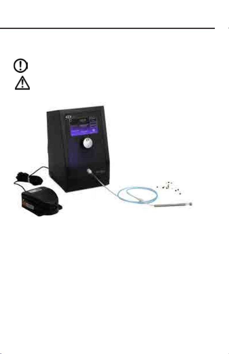
Parts List...................................................................................................................................... 3
Unpacking................................................................................................................................... 3
INSTRUMENT DESCRIPTION ........................................................................................................ 4
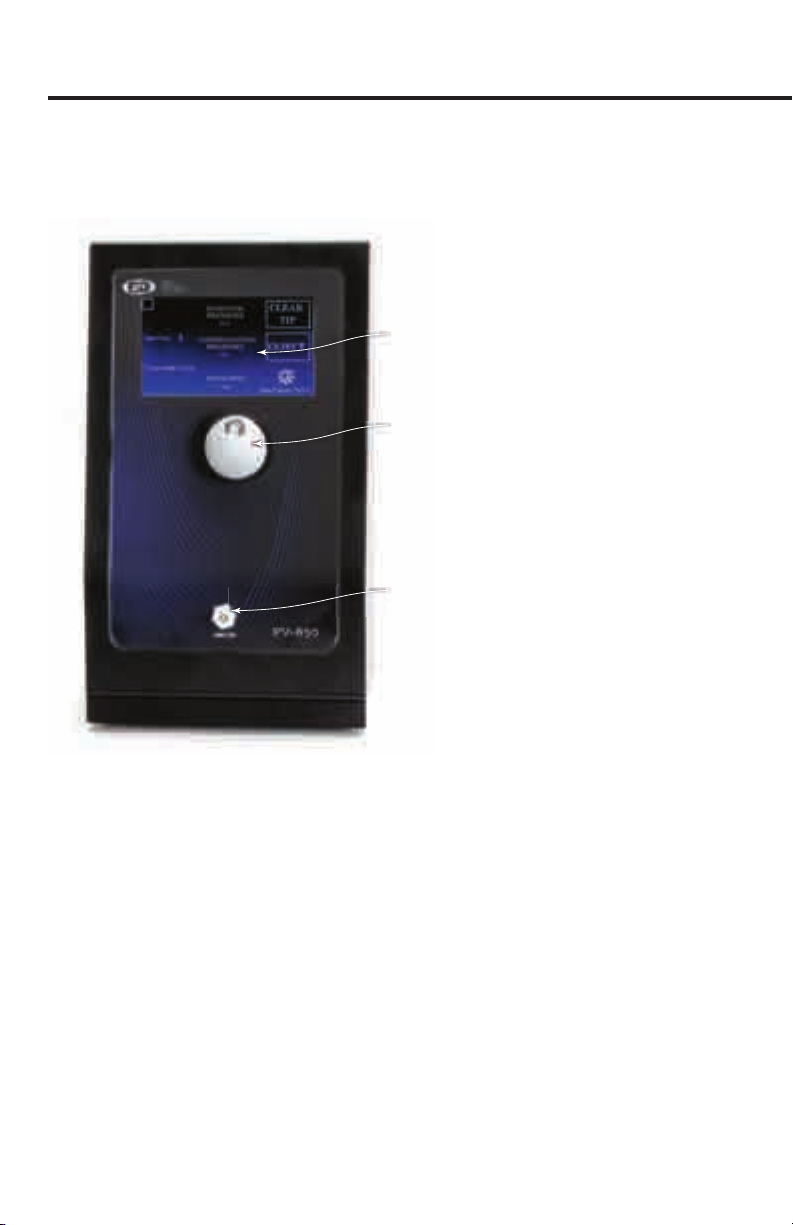
Front Panel ................................................................................................................................. 4
Rear Panel................................................................................................................................... 5
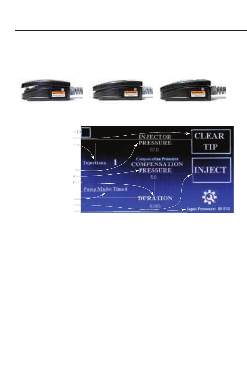
Foot Switch ................................................................................................................................. 6
Touch Panel Display ................................................................................................................. 6
Setting Menu.............................................................................................................................. 7
Setup............................................................................................................................................ 8
OPERATING INSTRUCTIONS.......................................................................................................11
Saving a Protocol.....................................................................................................................13
Loading a Protocol..................................................................................................................14
Changing the Pipette..............................................................................................................14
TECHNIQUES IN MICROINJECTION...........................................................................................15
Setting the Compensation Pressure ..................................................................................15
Manufacturing Micropipettes ..............................................................................................16
Calibrating Volume by Measuring Droplet........................................................................17
Calibrating Rate using a Known Volume ...........................................................................18
Multibarrel Microinjection ....................................................................................................19
MAINTENANCE ..............................................................................................................................20
Cleaning.....................................................................................................................................20
ACCESSORIES.................................................................................................................................20
TROUBLESHOOTING ...................................................................................................................21
SPECIFICATIONS............................................................................................................................22
APPENDIX A: DROPLET VOLUME..............................................................................................23
Volume of a Micropipette .....................................................................................................23
BIBLIOGRAPHY..............................................................................................................................24
DECLARATION OF CONFORMITY ..............................................................................................26
WARRANTY .....................................................................................................................................27
Claims and Returns ................................................................................................................27
Repairs.......................................................................................................................................27
Copyright © 2020 by World Precision Instruments. All rights reserved. No part of this publication may
be reproduced or translated into any language, in any form, without prior written permission of World
Precision Instruments, Inc.

ii World Precision Instruments

PV850
World Precision Instruments 1
ABOUT THIS MANUAL
The following symbols are used in this guide:
This symbol indicates a CAUTION. Cautions warn against actions that can cause
damage to equipment. Please read these carefully.
This symbol indicates a WARNING. Warnings alert you to actions that can cause
personal injury or pose a physical threat. Please read these carefully.
NOTES and TIPS contain helpful information.
Fig. 1—MIRO-ePUMP Microinjector requires an external pressure source.
INTRODUCTION
Designed to simplify intracellular injection and a variety of other microinjection tasks,
the PV850 uss aru ruat ar rs sur or ntn s t u nt
volumes range from picoliters to nanoliters. The port supplies positive pressure for
high-pressure ejection. The pressure port maintains a low positive “compensation” pres-
sur to t ntn tt tn nton uss to rnt u u ta trou
capillary action.
Timing, injection pressure and compensation pressure are adjusted independent-
ly using the touch screen interface. Time intervals can range from 2 seconds down
to s or ss nn on t nton rssur sttn nton rssur
interval is triggered by using a foot switch, manually, or a computer-controlled TTL pulse.
The PV850 s sn to nt r sa uantts o us su as rus nto
cells or small organelles. Pressure injection is an especially useful alternative to
troonoorss sn t os not anat t us o ar ons o ffrnt

2 World Precision Instruments
positive pressures may be applied–one for ejection at high pressure and a second,
or rssur to rnt a n o t tt aar aton
The PV850 offrs sarat ruat onsaton (a n rnton) an
ejection pressures with a precision timing circuit that switches from injection pressure
to compensation pressure automatically.
Features
• Regulated compensation and injection pressure
• Pressure output: 0.3-87 PSI
• Injection can be triggered manually using the touchscreen, by foot switch, or by a
computer-controlled TTL pulse
• Low volume tubing assembly
Benets
• Intuitive user-interface for injector
• Small footprint takes up very little bench space
• Easy to navigate with touch screen and control knob
• Inject into a single cell in picoliter volumes
Applications
• Microinjection of diverse compounds and biomolecules – DNA, RNA, proteins
• Pre- and post-implantation in embryos of various species – mice, rats, monkeys,
on s ras t
Notes and Warnings
!
WARNING: SECURE THE PIPETTE FIRMLY IN THE HOLDER. WHEN HIGH
PRESSURE IS APPLIED, A LOOSE PIPETTE CAN BE EJECTED FORCEFULLY.
DO NOT APPLY PRESSURES IN EXCESS OF 100 PSI (100 KPA).
!
WARNING: THIS INSTRUMENT IS FOR INVESTIGATIONAL USE ONLY IN
ANIMALS OR OTHER TESTS THAT DO NOT INVOLVE HUMAN SUBJECTS.

PV850
World Precision Instruments 3
Parts List
After unpacking, verify that there is no visible damage to the instrument. Verify that all
items are included:
() PV850
() oot st
() 300753 PV850 Capillary Kit which includes:
() tt asts (rn)
() tt asts (a)
() tt asts (r)
() tt asts (t)
() Ptt an
() San orns
() Ptt or
() un ass
() atr tun ass
() 3316 Input Kit for PicoPumps which includes:
() P ttn or ntron tan ruator
() ar tun
() auu ttn
() CBL102 a n on u to (a)
() 803130 Stereo splitter cable, 3.5 mm male to two female
() / Por atr
() nstruton anua (aaa onn at no/anuas)
Unpacking
Upon receipt of this instrument, make a thorough inspection of the contents and
check for possible damage. Missing cartons or obvious damage to cartons should be
noted on the delivery receipt before signing. Concealed damage should be reported
at once to the carrier and an inspection requested. Please read the section entitled
“Claims and Returns” on page 27 of this manual. Please contact WPI Customer
Sr an arts ar ssn at () or ustorsrno
Returns: o not rturn an oos to P tout otann ror aroa (
rur) an nstrutons ro Ps turns artnt oos rturn
(unautor) ot rt a rus a rturn snt s nssar us
the original container, if possible. If the original container is not available, use a suitable
substitute that is rigid and of adequate size. Wrap the instrument in paper or plastic
surroun t at ast (our ns) o so asorn atra or urtr
details, please read the section entitled “Claims and Returns” on page 27 of this manual.

4 World Precision Instruments
INSTRUMENT DESCRIPTION
Front Panel
Touch screen interface
Adjustment Knob
Injector Port
Fig. 2—The major features of the PV850 are labeled in this diagram.
Touch Screen Interface – The responsive panel allows for intuitive control. Touch
t nton ountr to rst t t tan rssur au to r t tan ar to
blow a blast of air through the pipette tip, a parameter to modify it using the knob, or
the settings area to adjust the settings.
Adjustment Knob – Rotate the adjustment knob to change the highlighted
aratr Prss t to to tn ross an n tun ontros
Injector Port – Plug the easy connect connector on the tubing into this port.

PV850
World Precision Instruments 5
Rear Panel
Foot Switch Connection*
Air Input Port
USB Port (not used)
Power Supply Connection
*Option: Use 803130 Y
Stereo Splitter for triggering
with a TTL signal
Power Switch
Fig. 3—The foot switch connection, power supply connection and power switch are located
on the back panel of the PV850.
Foot Switch Connection – Plug the connector from the foot switch into the
connection port marked with the foot switch icon. Press the foot switch to initiate a
t sun (t o) or to anua t rssur (anua o) s oot
st s a tosta st rss t aa to ntat an nton (S oot
St on a ) sn t CBL102 BNC cable and the 803130 Y stereo splitter,
you can trigger an injection via a computer-controlled +5 V TTL pulse.
USB Port –This interface is reserved for factory use only.
Power Switch o or on t unt rss t to st to o or off t
unit, press the toggle switch to O.
Power Supply Connection –Insert the power supply connector into this port and
u t otr n nto an / a outt
Air Input Port–This is the air supply for the injector. This pressure must be at least 6
PSI higher than the maximum injection pressure used.

6 World Precision Instruments
Foot Switch
The foot switch is a two-step switch, but the PV850 model activates whenever the
switch is depressed, either half-way or fully. Both positions have the same result. Both
positions trigger an injection.
Not depressed Half way depressed Fully depressed
Touch Panel Display
Injection Pressure
(PSI or kPa)
Compensation Pressure
(PSI or kPa)
Injection Time
(msec - 2 s max.)
(PSI or kPa)
(PSI or kPa)
Protocol Loaded
Clear Clogged Tip
Injection Counter
Mode
Injection Button
Settings Screen
(PSI or kPa)
(msec - 2 s max.)
(PSI or kPa)
(msec - 2 s max.)
2
Fig. 4—The Touch Panel Display gives you access to all the parameters and the settings menu.
Protocol Loaded – The number in the box in the upper left corner indicates the protocol
with stored parameters that is loaded. You can store and recall up to three of your most
used protocols in the PV850 memory. If the box is empty, no protocol is loaded.
Clearing Clogged Tip – Press Clear Tip to force a 500 ms burst of maximum pressure
( PS trou t nton t s an us t t os o
valves are closed when the compensation pressure is at zero. To exercise the CLEAR
function, you can set it at 0.01.
Injection Counter r t ou rss t oot st a t a (n t ort
s na) t injection counter increments. To reset the injection counter to zero,
touch the injection counter on the display.
Injection Pressure – Touch the parameter and rotate the knob to adjust the pressure
used to inject. When you depress the foot switch all the way, this is the pressure that
is forced through the injection tip.
Compensation Pressure – Touch the parameter and rotate the knob to adjust the
onsaton rssur tat s us to rnt t a n o t tt
Injection Time – Touch the parameter and rotate the knob to adjust the length of
each injection.

PV850
World Precision Instruments 7
Mode – This indicates if the pump mode, either Timed or Manual.
Injection Button (Manual)– Use this button to manually initiate an injection.
Settings Screen ou anr n t sttns ara (otto rt ornr) o t
screen to access the settings menu. This area also shows the status of the warning
tones.
Setting Menu
Mode
Units
Save/Load Protocols
Self Test Button
Port Status (On/Off)
Back Button
Mode
Units
Fig. 5—From the Settings menu, you can save and load parameters, choose the mode, set
the units, toggle the MICRO-ePORE™ o or on, silence the tones, and toggle the injection
port o or on.
Mode – Choose either the Manual or the Timed checkbox to determine the injection
mode. Manual control allows for injection pressure to be applied for as long as the
foot switch is fully depressed. Timed injections use the duration set on the main screen.
Units – Select one of the checkboxes to set the display to either PSI or kPa.
Save/Load Protocols – The PV850 can store your three favorite parameter sets
(rotoos) On t an srn st t aratrs as sr n rss on o
the
Save buttons. For example, press SAVE1 to save the parameters as Protocol 1. To load a
st o sa aratrs (a rotoo) rss t arorat O utton nur o
the loaded protocol displays in the box in the upper left corner of the main screen.
Self Test Button
– The Self Test runs whenever the unit is powered on. To initiate a test
manually, press this button. It runs a series of programmed diagnostics and displays
results on the screen.
Port Status – Port ON indicates that the injection port is enabled. To disable the port,
touch the Port ON button. The button will change to Port OFF. To re-enable the port,
press the Port OFF button, and the button will change to Port ON.
Back Button – Touch the Back button to return to the main screen.

8 World Precision Instruments
Setup
/ ar tun (nu) an ut to t t s us or onntn an ar u
or tan sot tun (nu t t aar t) s us or onntn t
rott ors to t rontors outut (INJECTOR) orts
Installing Hard Tubing
Quick Connect Fitting
Collar1/4 in. Tubing
To insert, push the tubing in firmly.
To remove, push in on the collar
while pulling the tubing out.
Fig. 6—The air input port is located on the rear panel.
!CAUTION: Do not remove tubing holders. These parts are intended to remain
on the pump.
o nsta t ar tun r nsrt tun nto t uonnt ttns on t
rear of the instrument. When the tubing is inserted far enough, it engages and cannot
be pulled out. To remove the tubing, press in on the surrounding collar while pulling
the tubing out. Plastic tubing can be disconnected easily, while metal tubing may
rur or ffort
Making Connections and Startup
1. With the PV850 turn off a t oon onntons
• Connect Power Supply to the rear of the unit and plug it into a wall outlet.
• Plug the Foot Switch Connector into the Foot Switch Port.
Fig. 7—The Foot Switch Connector is labeled “Rear Panel.” Do NOT plug it into the injection
port on the front panel.
NOTE: DO NOT connect the capillary kit hose to the PV850.
2. Verify that the capillary kit hose is disconnected from the Injection Port. Then,
power on the PV850. On power up, the following happens:
• The power up screen appears.
• The PV850 performs a self-test.
After the self-test completes, the main display screen appears. See “Touch
Pan sa on a t sas t onuraton sttns us n t
or off t ast t

PV850
World Precision Instruments 9
Fig. 8—(Left) The power up screen shows the software revision on your PV850.
Fig. 9—As the self-test runs through the programmed diagnostic sequence, the display
shows the results.
3. Press the touchscreen to access the main screen. By default, the injection port is
disabled. Tap the warning or the Settings icon to enable the Injection Port.
Fig. 10—The warning indicates that the injection port is disabled by default on startup. To
enable the port, press the Port OFF button. The Port OFF message will become the Inject
button.
Assembling the Capillary Kit
Pipette Holder
Pipette Handle
Tubing Assembly
Adapter Tubing Assembly
Gasket
Cap
Pipette
Tubing connected to the barb
Body
Fig. 11—The 300753 Capillary Kit must be properly assembled.
1. Slide the bare end of the Adapter Tubing Assembly through the Pipette Handle.
2. Connect it to the barb of the Pipette Holder Body. Be careful so that the barb
does not break when attaching or removing the tubing.
3. Slide the Pipette Handle over the barb and carefully screw it onto the Body of the
Pipette Holder. Be careful not to cross thread it.
4. Place a gasket of the correct size in the cap. Refer to the table below. Then, insert
t unt n o t rott (u aar ass) nto t a trou
the gasket and into the body. Screw the cap in place. The screw cap and rubber
ast r o t ass rott

10 World Precision Instruments
Gasket Color Green Black Red White
Ptt atr () 1.0 1.2 1.5 1.65
!
WARNING: DANGER OF INJURY EXISTS IF THE PIPETTE IS INSECURE. HIGH
PRESSURE CAN CAUSE EJECTION AT HIGH VELOCITY.
5. The other end of the small tubing has a quick connector. Connect it with the blue
PV850 Tubing Assembly provided.
6.
Verify that the Injection Port is disabled. If not, touch the Settings area of the
display
to access the Settings menu and touch the Port ON button to set it to Port OFF
.
7. Align the easy-connect Injector connector with the injector port on the front of
the PV850, slide the connector securely into the port and attach it with a slight
clockwise twist.
Fig. 12—(Left) Align the connector with the Injection Port, slide the connector in position and
rotate the connector a little clockwise to lock it into place.
Fig. 13—(Right) The PicoNozzle is connected to the injection port.
Connecting to a Pulse Generator for TTL Control
If you wish to use a computer or pulse generator to send a TTL pulse to trigger an
injection, connect the 803130 Y stereo splitter to the foot switch port on the rear
of the PV850. Connect the CBL102 jack to one of the female ports on the Y stereo
splitter. Plug the BNC cable into the appropriate TTL port.
803130
Y Stereo Splitter
CBL102
Stereo jack to BNC
To computer or
pulse generator
Connect to
Foot Switch
Port
Fig. 14—Use the CBL102 and the 803130 to congure the system for a TTL trigger.

PV850
World Precision Instruments 11
The µPump will inject on the high to low transition of the incoming TTL pulse.
No Injection
INJECTION
No Injection
Fig. 15—The injection happens on the high to low transition of the TTL pulse.
OPERATING INSTRUCTIONS
Changing the Injection Parameters
Prss anr n t sttns ara to ass t Sttns nu Prss Port Off to
turn on t rssur ort (PO O)
Fig. 16—(Left) Touch the setting area in the bottom right corner to access the Settings menu.
Fig. 17—(Right) Touch the Port OFF button to enable the injection port.
2. On the Settings screen you may choose the Pump Mode as TIMED or MANUAL. In
the MANUAL mode, the valve stays open for as long as the Inject button or foot
st s rss n t o t ran s
• MANUAL mode–The pressure valve opens and remains open as long as the
Inject button or foot switch is pressed or a 5 V TTL pulse is triggered by an
external pulse generator.
• TIMED mode–An electronic timer controls the duration that the pressure valve
stays open, and the Inject button, foot switch or 5V TTL trigger serves only to
start the timer. Although the timer control allows you to set sub-millisecond
burst intervals, the true burst interval is limited by the mechanical response of
the valve, which is about 0-2 seconds, depending on the pressure.
outut onntor rous a o outut ( ) orrsonn to
the time interval during with the eject pressure valve is energized. At all other
ts t ontor outut s o ( )
3. To change the parameters, just touch the screen on the parameter you want to
change. A box appears around the parameter to highlight it. Adjust the parameter
by turning the knob. To change the dial adjustment speed, press the knob on the
front of the PV850. The snail mode allows movements in 0.01 increments to the
compensation pressure only, and only when it is below 3.0 PSI. Both conditions
must be met. The running man changes it in increments of 0.
NOTE: When adjusting the COMPENSATION PRESSURE under 3.0 PSI, you may
set it in 0.01 PSI increments.

12 World Precision Instruments
Gross Adjustment
Fine Adjustment
Fig. 18—Touch the parameter in the center column of the screen that you want to adjust
and rotate the knob to modify the parameter. Press the knob to toggle between gross and
ne tuning adjustments, indicated by the running man and the snail on the screen.
4.
Two seconds after a parameter is adjusted, it is saved into the memory. If you move from
on aratr to t nt or to sons t rst aratr s autoata sa
into the memory as the working parameter. This setting will be recalled on power up.
NOTE s s ffrnt ro san aratr sts (rotoos) to oa
5. Activate an injection using one of these methods. You will hear an audible alarm
when the injector port is activated.
• Press the foot switch.
• Press the Inject button on the touch screen controller.
• Send a TTL pulse from a pulse genertator. See “Connecting to a Pulse
Generator for TTL Control” on page 10.
Resetting the Injection Counter
This area in the left column shows the injection count. Whenever the foot switch is
depressed or the Inject button is pressed, the injection counter increments. Reset it to
zero by pressing the injection area of the main display touchscreen.
Fig. 19—Press Injections to reset the injection counter.

PV850
World Precision Instruments 13
Adjust the PV850 Settings
sttn ston (otto rt ornr o t an srn) sas t urrnt sttns
for the
PV850 o (anua or )
Fig. 20—(Left) The Setting area is located in the bottom right corner of the main screen.
Fig. 21—(Right) Touch the Setting area to display the Settings menu.
1. To modify these settings, press the Settings section on the touchscreen.
2. From there, you can make the following adjustments:
• Change the PV850 o (anua or t)
• an t rssur unts sa on t an srn (PS or Pa)
3. Press the BACK button to save the settings and return to the main screen.
Saving a Protocol
After you have adjusted the parameters, you can save the set of parameters as a
protocol. PV850 stor u to tr () rotoos
1. Set the parameters, as desired.
2. Press the Settings section on the touchscreen to access the Settings menu.
Fig. 22—The Settings menu lets you save a protocol or load a saved protocol.
3. To save the existing set of parameters from the main screen, press the SAVE1,
SAVE2 or SAVE3 button. The parameters are saved in Protocol 1, Protocol 2 or
Protocol 3, depending on which SAVE button you chose.
4. Press the BACK button to return to the main screen.

14 World Precision Instruments
Loading a Protocol
Saved protocols may be recalled, and this loads the saved parameters for use. When
a rotoo s oa t rotoo nur ( or ) aars n t o oat n t
upper left corner of the main screen.
1. Press the Settings section on the touchscreen to access the Settings menu.
Fig. 23—The Settings menu lets you save a protocol or load a saved protocol.
2. To bring up a saved protocol with the PV850 parameters, press the LOAD 1,
LOAD2 or LOAD3 button. The unit loads the saved parameters of Protocol 1,
Protocol 2 or Protocol 3, depending on which LOAD button you chose.
3. Press the BACK button to return to the main screen.
Changing the Pipette
o an t tt turn off t nton PO to ao tn t rsror
button indicates the present state of the port.
o turn off t nton Port rss t Sttns ston on t tousrn
Fig. 24—The Settings menu lets you save enable or disable the Injection Port by pressing the
Port ON/Port OFF toggle button.
2. Press the Port ON button to disable the Injection Port

PV850
World Precision Instruments 15
3. Press the BACK button to save the settings and return to the main screen. A
warning indicates that the Injection Port is disabled.
Fig. 25—When the Injection Port is disabled a notice appears on the main screen.
4. To install the micropipette, see “Assembling the Capillary Kit” on page 9.
5. When the micropipette is properly installed, click on the Settings area to access
the Settings menu and press the Port OFF button to enable the Injection Port.
TECHNIQUES IN MICROINJECTION
The PV850 as sn or ann tass t ronton o u nto s
In this section, we will look at several important things to keep in mind when working
with the PV850.
Setting the Compensation Pressure
The onsaton rssur s us to ountraan t aar aton o t u
an nto t tts ou nsrt an t tt nto u ou an s a
meniscus rising from the capillary tip.
Set the Compensation Pressure parameter by touching the Compensation Pressure
parameter on the main screen and adjusting the knob until the meniscus stops at the
sr oston n t rott n an aatons oor or uorsnt
s sso n t nton u aar fft a osr t t
oor an at t t o t tt n t u os nto t tt t oor
of the tip becomes lighter. If the compensation pressure is higher than the capillary
rssur t u oos out o t tt souton aroun t tt
colored. Adjusting the compensation pressure prevents this from happening.
NOTE: When adjusting the COMPENSATION PRESSURE under 3.0 PSI, you may set it in
0.01 PSI increments.
Understanding how aar aton auss t ront n o t tt s ou to
orrt us t onsaton rssur o rat s trn t aar
action and the tip size. Since the tip size is often determined by the requirement of
the application, controlling the compensation pressure becomes the main option to
nat t uta o u aar aton
NOTE: The pressure of capillary action is determined by the inner diameter of
the glass capillary where the meniscus of air/liquid interface is located. It has
nothing to do with the pipette tip size.

16 World Precision Instruments
If you assume the pipette tip is a cylindrical shape, the pressure of capillary action can
be described by the LaPlace equation:
P=4γcosθ/
γ= surface tension
θ= contact angle between the water and glass
d= inner diameter of the capillary where the meniscus is
located
n ost ass an assu t ontat an or ass an atr s ro (unss
t ass sura s trat) ro ts uaton s tat t sar t ns
diameter, the greater the capillary action. The capillary pressure can vary a thousand
times when the meniscus is moved from a 0.5 µm ID tip to the 0.5 mm shank.
rssur at t s aout PS (n auous souton) at t san
be only 0.08 PSI. Using one regulator to counterbalance the pressure in such a large
dynamic range is not practical. 10 PSI can counterbalance a meniscus at the section of
tip where the inner diameter is 4 µm.
In practice, this is the highest pressure ever needed. On the lower pressure end, it
os ut to at ountraan t aar rssur n t nsus
is at the shank of the pipette. However, a 0.1–0.2 PSI pressure imbalance will not
aus a snant ro t t s sa nou rat o t u an t
o rsstan aus rton ro t ass a ot to sto t souton
o at ts rssur
TIP t ost rssur sttn s nfft at rntn t tt u ro
leaking out, try setting the compensation pressure to zero to see if the gravity and
rton ar sunt to ountraan t ront
TIP aar aton an aso ru an a roo u (su as
son o) n t ro san souton t an ot nat
sann t san o t tt (sanaton nrass t θin the LaPlace equation
to )
Manufacturing Micropipettes
Pulling suitable micropipettes is one of the biggest obstacles to taking full advantage
of the PV850 ot ar an sta ans ar rur ou o u t s
markedly dependent on the micropipette tip size.
When using micron-sized tips a reduction in tip-size of a few percent may give an
orr o antu ffrn n t o rat t t ss ss tan rssur
ton os nrasn ut an sa sts ust tan
The most important of these steps is cleaning the glass. Small amounts of dust or
grease can easily clog micron-sized tips. Cleaning with chromic acid solutions before
pulling the electrode is commonly performed, but care must be taken to thoroughly
rns t tts to ro a tras o t ro a as so ant or
glass. Some researchers prefer hydrochloric or nitric acid.
Silanization of the glass is also recommended for small tips. With 1 µm and smaller
tips, capillary action becomes prohibitively large, and the hydrophilic surface of the
Table of contents
Other WPI Laboratory Equipment manuals
Popular Laboratory Equipment manuals by other brands

Velp Scientifica
Velp Scientifica AREX DIGITAL PRO F20500410 instruction manual

Miele
Miele PG8582 CD Installations plan

Aqua Ultraviolet
Aqua Ultraviolet Classic Series Replacement

Netafim
Netafim NetaJet NMC User and installation manual

Cleaver Scientific
Cleaver Scientific CSL-CELLAS instruction manual

CTC Union
CTC Union INJ-IG02-PH Quick installation guide