Mills TS MILLS Mounting instructions
TS MILLS
USE MANUAL
Infrastructure

USE MANUAL
TSMILLS

©Copyright 2016 Mills Estruturas e Serviços de Engenharia S.A.
The copying of this publication by any means or process is forbidden, even if
partially, without previous and written authorization both of the owners and the
intellectual authors.
THIS MANUAL WAS PRODUCED AT
ENGENHARIA NACIONAL
Mills Estruturas e Serviços de Engenharia S.A.
Estrada do Guerenguê, 1381 - Curicica
22713-001 - Rio de Janeiro | RJ
Tel: (21) 2132-4338
www.mills.com.br
SUPERVISED BY
Avelino Pinto da Silva Garzoni
ENGINEERING DIRECTOR
Vinícius Monteiro
ENGINEERING MANAGER
Claudinei Palma de Lima
TECHNICAL MANAGER
Miguel Henrique de Oliveira Costa
TECHNICAL COORDINATOR
Cardec Barcelos Lomeu Bastos
TECHNICAL COORDINATOR
Mário Luiz Sartorio Valiati
DESIGN COORDINATOR
TITLE
USE AND ASSEMBLY MANUAL | TS MILLS SYSTEM
ISSUE 2
Maio - 2016 | Edição 2 — 04.09.05.2016
TECHNICAL TEXT
Cardec Barcelos Lomeu Bastos
Claudinei Palma de Lima
Mário Luiz Sartorio Valiati
DESIGNS, ASSEMBLIES AND ILLUSTRATIONS
João Gabriel Coelho de Salles Victor
Laryssa da Cunha Macedo
Priscilla dos Santos Oliveira
Roberta da Costa Melo
DESIGNS, ASSEMBLIES AND ILLUSTRATIONS
André Durval de Andrade
Gustavo dos Santos Araújo
Jeisson Alves de Carvalho
Laryssa da Cunha Macedo
Marcelo Amancio Lages
Priscilla dos Santos Oliveira
Roberta da Costa Melo
Robson Ferreira das Neves
Thaís Cristina de Carvalho Araújo
Márcia Rita Santanna da Silva
TEXT EDITION
Laryssa da Cunha Macedo
Priscilla dos Santos Oliveira
Roberta da Costa Melo
COLLABORATORS
Wagner de Oliveira
Yuri de Amorim
REVISION
Cardec Barcelos Lomeu Bastos
Claudinei Palma de Lima
Bruno da Costa Ribeiro
Mário Luiz Sartorio Valiati


SUMMARY
10 SYSTEM DESCRIPTION
11 POSSIBILITY OF USING THE TS MILLS SYSTEM
SLABS AND BEAMS
16 TS MILLS SYSTEM ELEMENTS
TS METALLIC TOWERS
18 TUBULAR FRAMES
TS3 AND TS4 FRAME
21 STANCHIONS
22 STANCHIONS ASSEMBLY
23 DX - “X” DIAGONALS FOR BRACING
25 DX VISUAL IDENTIFICATION
26 DTT TS - TRANSVERSE DIAGONAL FOR TS
28 DTT VISUAL IDENTIFICATION FOR TS
29 DTT USE RULE
31 SHOES
33 FIXED SHOE
34 ADJUSTABLE SHOE -TS
ELONGATED SHOE
35 USE OF ADJUSTABLE AND ELONGATED SHOES IN UNEVEN
SUPPORT
36 SUPPORTS FOR TS
37 SINGLE ADJUSTABLE SUPPORT TS
38 DOUBLE ADJUSTABLE SUPPORT TS
39 DOUBLE BASE FOR SUPPORT
40 RULE FOR USING THE DOUBLE BASE
41 KNEE BRACE
43 10T METALLIC TOWER
44 COMPONENTS OF THE 10T METALLIC TOWER
10T FRAME
45 10T STANCHION
46 DX 10T - “X” BRACING DIAGONALS
47 DTT 10T - TUBULAR TRANSVERSE DIAGONAL

48 10T ADJUSTABLE SHOE
49 10T ADJUSTABLE SUPPORT
50 ACCESSORIES FOR TS AND 10T TOWER
COUPLING ANGLE
52 METALLIC TOWER ASSEMBLY (TS OR 10T)
54 MILLSLOCK TOWER
55 MILLS TOWER
56 METALLIC STRUTS
57 METALLIC STRUT MODELS
59 TELESCOPIC SUPPORT I (WITH AND WITHOUT SHOE)
60 TELESCOPIC SUPPORT II (WITH AND WITHOUT SHOE)
61 2T STRUT
62 ALUMILLS STRUT
63 DECK STRUT
65 ACCESSORIES FOR FIXED SUPPORT STRUTS
66 TRIPODS
67 TUBULAR TRIPOD
68 ALUMILLS TRIPOD
69 UNIVERSAL TRIPOD
70 TRIPOD USE RULE
71 ALUMILLS PITCHFORK
72 CROSSHEADS AND SUPPORT T
CROSSHEAD I
73 CROSSHEAD II
74 SUPPORT T
75 METALLIC BEAMS
76 ALUMINUM BEAMS (VA 140, VA165, VA 165 DOUBLE CORE)
78 STEEL BEAMS (VJ2”, VJ3”, VJ5” AND VJ7”)
79 VJ2
80 VJ3
81 VJ5
82 VJ7

83 SUPPORT FOR BODYGUARD VJ5 AND VA 140
84 METALLIC SHAPES
SHAPE I (I 6”, I8”, I10” AND I12” AMERICAN STANDARD)
85 ALUMA RISER
86 RISER SPLICE PLATE
87 OTHER ELEMENTS
METALLIC YOKES
88 INNER YOKE
89 PERIPHERY YOKE
91 PERIPHERY YOKE BODYGUARD SUPPORT
GUIDE SYSTEM AND SUPPORTS FOR BUCKETS
GUIDES FOR REPROPPING RANGE
CONTINUOUS GUIDE
92 BUCKET SUPPORT
OPERATION PRINCIPLE OF THE COMPONENTS
93 ASSEMBLY STEPS
96 PIPES AND CLAMPS
MILLS PIPE
97 CLAMPS
1/49 AND 2/49 CLAMP
2/49/60 CLAMP
98 TYING COLUMN
99 FIXED AND HINGED CLAMP
100 PILLAR PLUMBER II
101 METALLIC CLIP, SUPPORT PLATE, TIE ROD AND WING NUT
102 TECHNICAL USE INSTRUCTIONS
PILLARS
PILLAR LOCKING AND PLUMBING
104 BEAMS
OUTER BEAMS / PERIPHERY / EDGE
STRUTS WITH CROSSHEADS AND T SUPPORT
105 PROPPING WITH TOWER
106 PROPPING USING BRACE

107 PERIPHERY YOKES
108 INNER BEAMS
PROPPING WITH CROSSHEADS AND T SUPPORT
109 PROPPING WITH TOWER
111 INNER YOKES
114 BEAM LOCKING
115 SOUND SLABS PROPPING
119 BRACING WITH STRUTS
120 BRACING WITH TOWERS
121 MIXED PROPPING
DOUBLE AND SINGLE BASE PROPPING
122 SAFETY RECOMMENDATIONS
SAFETY, PPE’S AND TOOLS
123 DESCRIPTION OF THE TS MILLS TS MILLS SYSTEM COMPONENTS
137 ANNEXES

MANUAL DE UTILIZAÇÃO |BALANÇO HIDRÁULICO
10 www.mills.com.br
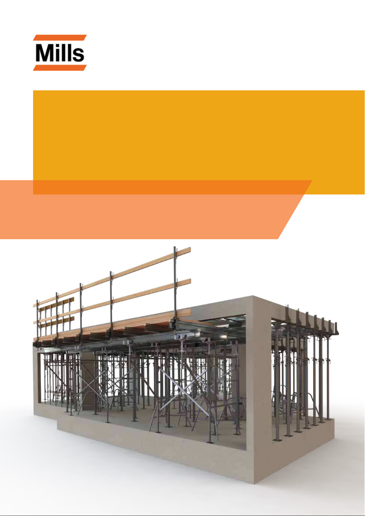
1. SYSTEM DESCRIPTION
A light, quick and exible system, comprised by metallic towers, metallic (steel/aluminum) struts, metallic
(steel/aluminum) beams and accessories.
It is ideal for the propping of slabs and beams of building works (residential, commercial or industrial),
because it enables a high productivity index, due to the handling facility, the lightness of its components
and the system exibility, meeting all geometries.
METALLIC BEAMS
Page 75
METALLIC YOKES
Page 87
STRUTS
Page 57
BODYGUARD
Page 91
METALLIC TOWERS
Page 16

UNIDADE DE NEGÓCIOS INFRAESTRUTURA
11
MILLS ESTRUTURAS E SERVIÇOS DE ENGENHARIA S.A.
1.1. POSSIBILITIES OF USING THE TS MILLS SYSTEM
1.1.1. SLABS AND BEAMS
SITUATION 1
Propping of slabs and beams molded in loco
The TS Mills System has the right solution for your in-loco molded slab and beam independently of the
dimensions; we have a wide array of equipment and accessories, with varied possibilities of solutions
for your work, using metallic towers and struts.
DETAIL
Propping of slabs and beans
molded in loco

MANUAL DE UTILIZAÇÃO |BALANÇO HIDRÁULICO
12 www.mills.com.br
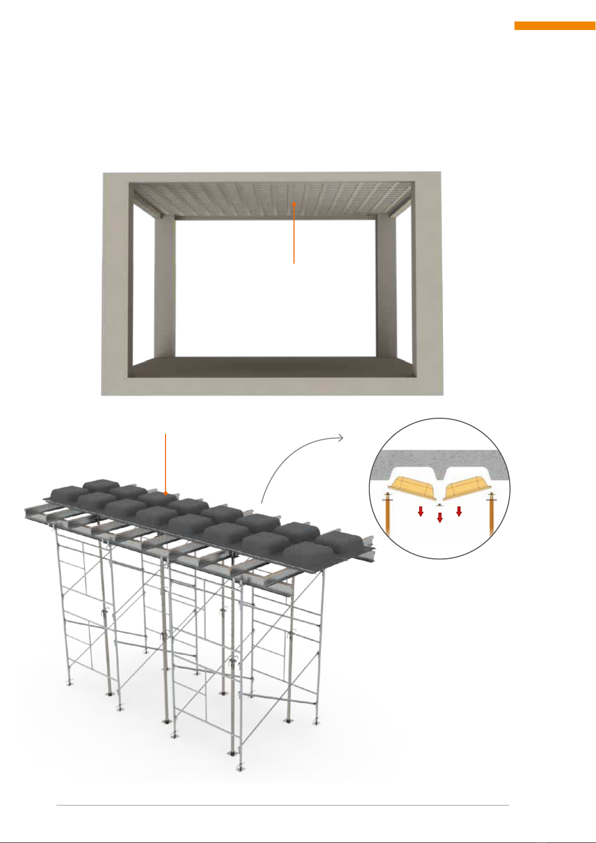
SITUATION 2
Prestressed slab propping
With a light propping comprised of struts and towers, we can give the practicality that your slab requires.
DETAIL
Propping of precast slabs
UNIDADE DE NEGÓCIOS INFRAESTRUTURA
13
MILLS ESTRUTURAS E SERVIÇOS DE ENGENHARIA S.A.
SITUATION 3
Propping of raft slabs
The TS Mills System has a line of equipment and accessories allowing using the same conventional
propping in at slabs, to comprise the repropping, providing more agility to the works, allowing the
entire horizontal and vertical propping to be assembled in the next oor.
BUCKET SYSTEM
Page 92
DETAIL
Raft slab
MANUAL DE UTILIZAÇÃO |BALANÇO HIDRÁULICO
14 www.mills.com.br
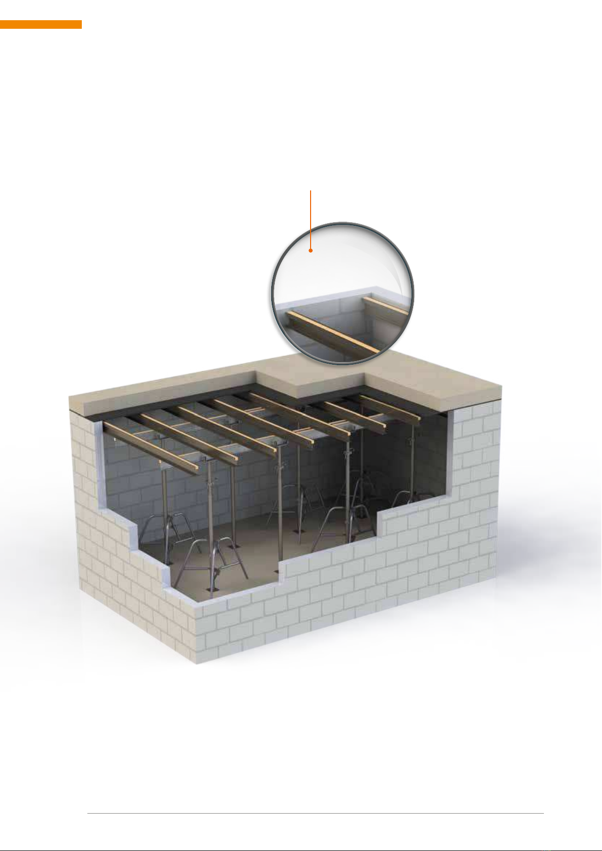
SITUATION 4
Slab propping with structural brickwork
With a light propping comprised of struts and towers, we can provide the agility that your work requires.
DETAIL
Beamwork for slab propping
UNIDADE DE NEGÓCIOS INFRAESTRUTURA
15
MILLS ESTRUTURAS E SERVIÇOS DE ENGENHARIA S.A.
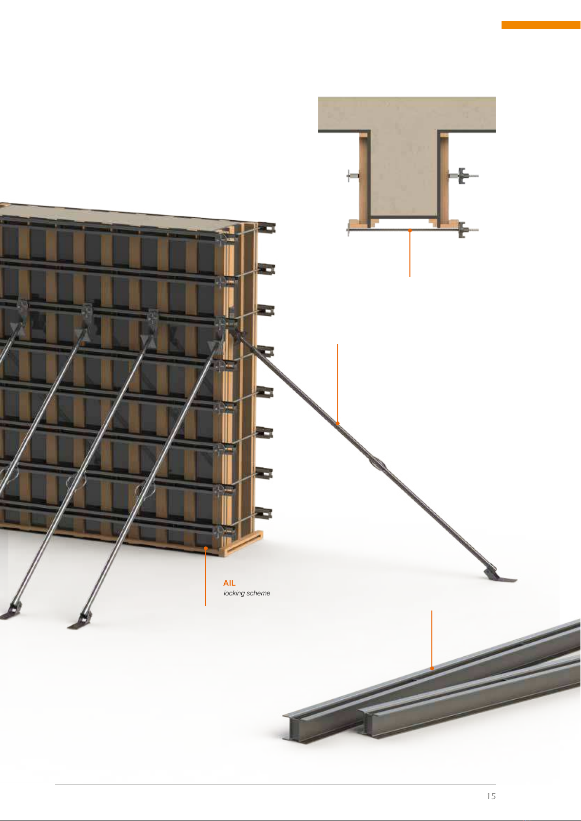
SITUATION 5
Locking of pillars and beams
As an integrating part of the TS MILLS System,
we have a line of equipment directed to the locking
of Pillars and Beams, allowing more safety and
agility for your works.
DETAIL
Pillar locking scheme
RR TIE ROD
Page 102
DETAIL
VJ2 Beam
PILLAR PLUMBER
Page 101
MANUAL DE UTILIZAÇÃO |BALANÇO HIDRÁULICO
16 www.mills.com.br
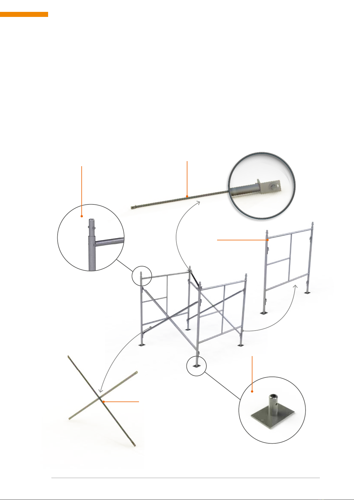
2. TS MILL SYSTEM ELEMENTS
2.1. TS METALLIC TOWERS
The TS metallic towers system is a composition of metallic structures formed by the tting of the
braced tubular frames by “X” diagonal elements. The assembly formed by two frames and two diagonal
elements (DX) is called module.
Its multiple models, measures and accessories offer assembly alternatives that meet several types of
works, mainly where a support structure is required as a way of accessing a certain height.
MAIN COMPONENTS OF THE METALLIC TOWER
DX
Page 23
STANCHION
Page 21
SHOES
Page 31
TS FRAME
Page 18
DTT/TS
Page 26
UNIDADE DE NEGÓCIOS INFRAESTRUTURA
17
MILLS ESTRUTURAS E SERVIÇOS DE ENGENHARIA S.A.
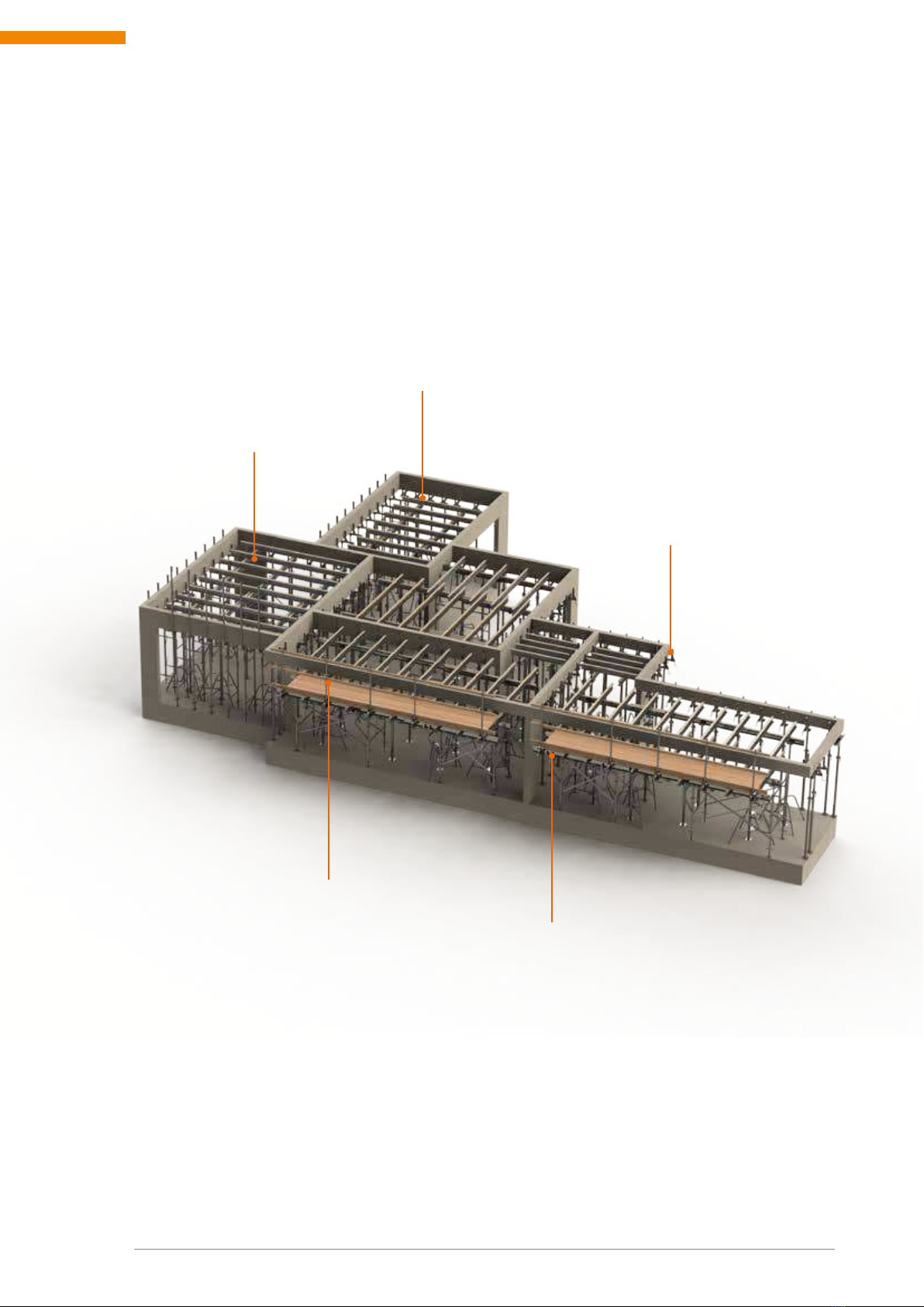
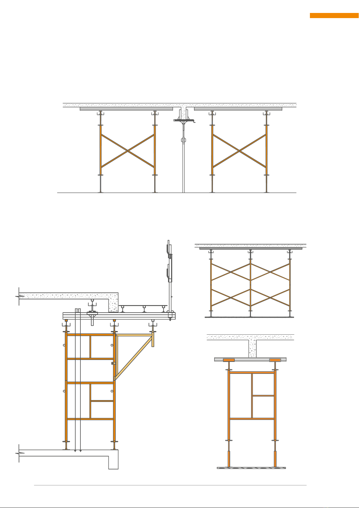
Periphery beam propping with
service platform.
▼
Slab propping with
one module tower.
►
Slab propping with two modules towers
interconnection.
▼
Inner beam propping with
tower with a module.
►
Since it is a practical, safe and easily assembled system, it does not require specialized labor. Therefore,
your system is part of the day to day of countless workers and foremen, such as load towers in the
propping of beams and slabs.
PROPPING EXAMPLES WITH TS METALLIC TOWER

MANUAL DE UTILIZAÇÃO |BALANÇO HIDRÁULICO
18 www.mills.com.br
2.1.1. TUBULAR FRAMES
This line of scaffolds is comprised of frames that differ from each other in width and in height. It is
compact and easily assembled.
Main element of the TS tower, responsible for transmitting the actuating loads to the support. It sets the
width (in the plant) of the tower: TS 3 = 1.50 m or TS 4 = 1.00 m.
01 - FRAME TS
Description Width (L) HEIGHT (H) Weight Load*
1TS-3A 1537 mm 1500 mm 18,600 kg 20 kN/post
2TS-3B 1537 mm 1250 mm 16,820 kg 20 kN/post
3TS-3C 1537 mm 1000 mm 14,100 kg 20 kN/post
4TS-4A 990 mm 1500 mm 16,050 kg 20 kN/post
5TS-4B 990 mm 1250 mm 14,280 kg 20 kN/post
6TS-4C 990 mm 1000 mm 11,920 kg 20 kN/post
(*) Load capacity per post.
(*) Review the load decrease chart
L
H
3
2
1
TS3 FRAME
5
6
4
Due to the number of modules, the allowable strengths of the posts
should be taken into account, according to the load decrease curve
chart. See page 144.
MAXIMUM LOAD PER POST
20 kN = 2000 kgf
2.1.1.1. TS3 AND TS4 FRAME
QUADRO TS4
UNIDADE DE NEGÓCIOS INFRAESTRUTURA
19
MILLS ESTRUTURAS E SERVIÇOS DE ENGENHARIA S.A.
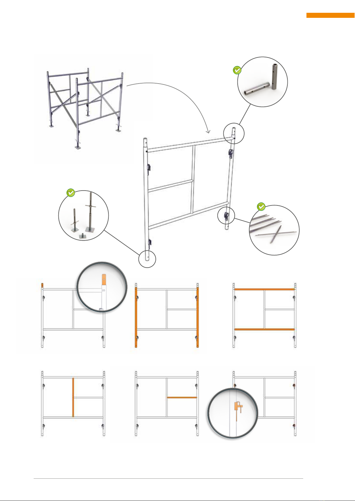
STANCHIONS
UNION
LEGS
STEP
CROSSPIECES
DIAGONAL ELEMENTS
LOCKS
STANCHION
Page 21
SHOES
Página 31
DX DIAGONAL ELEMENTS
Page 23
NOMENCLATURE OF THE PARTS OF A FRAME
Other Mills Construction Equipment manuals


