Milltronics CVCC User manual

CVCC
CURRENT VOLTAGE COMMUNICATION CONVERTER
September 2001
COMMUNICATION CONVERTER
Instruction Manual
*7ML19981FG01*

© Siemens Milltronics Process Instruments Inc. 2001
Safety Guidelines
Warning notices must be observed to ensure personal safety as well as that of others, and to
protect the product and the connected equipment. These warning notices are accompanied
by a clarification of the level of caution to be observed.
Qualified Personnel
This device/system may only be set up and operated in conjunction with this manual.
Qualified personnel are only authorized to install and operate this equipment in accordance
with established safety practices and standards.
Warning: This product can only function properly and safely if it is correctly transported,
stored, installed, set up, operated, and maintained.
Note: Always use product in accordance with specifications.
Copyright Siemens Milltronics Process
Instruments Inc. 2000. All Rights Reserved Disclaimer of Liability
This document is available in bound version and in
electronic version. We encourage users to
purchase authorized bound manuals, or to view
electronic versions as designed and authored by
Siemens Milltronics Process Instruments Inc.
Siemens Milltronics Process Instruments Inc. will
not be responsible for the contents of partial or
whole reproductions of either bound or electronic
versions.
While we have verified the contents of
this manual for agreement with the
instrumentation described, variations
remain possible. Thus we cannot
guarantee full agreement. The
contents of this manual are regularly
reviewed and corrections are included
in subsequent editions. We welcome
all suggestions for improvement.
Technical data subject to change.
MILLTRONICS®is a registered trademark of Siemens Milltronics Process Instruments Inc.
Contact SMPI Technical Publications at the following address:
Technical Publications
Siemens Milltronics Process Instruments Inc.
1954 Technology Drive, P.O. Box 4225
Peterborough, Ontario, Canada, K9J 7B1
Email: techpubs@milltronics.com
For the library of SMPI instruction manuals, visit our Web site: www.milltronics.com

7ML19981FG01 CVCC – INSTRUCTION MANUAL Page 1
Specifications
Power
• 115/230 Vac, 50 VA, 50/60 Hz - std.
• 100/200 Vac, 50 VA, 50-60 Hz - special
Fuse
• 1 A, MDL slo-blo or equivalent
Communication
• 20 mA bipolar current loop, bidirectional
- cable: Belden 9552, two pair shielded twisted, 18 ga.
• RS-232C, bidirectional
- cable: Belden 9552, two pair shielded/twisted, 18 ga.
- cable length: 15 m (50 ft) maximum
• RS-422, bidirectional
- cable: Belden 9553, three pair shielded/twisted 18 ga.
- cable length: 15 m (50 ft) maximum
Operating Temperature
• -20 to 60°C (-5 to 140°F)
Weight
•2.7Kg(5lb)
Enclosure
• general purpose
• 203 mm (8") W x 254 mm (10") D x 84 mm (3.3”) H
cvccfinal.fm Page 1 Thursday, September 6, 2001 2:17 PM

Page 2 CVCC – INSTRUCTION MANUAL 7ML19981FG01
About the CVCC
The CVCC (Current to Voltage Communication Converter) is a passive communication link
used to interface Milltronics equipment using proprietary 20 mA bipolar communication
format with RS-232C or RS-422 communication of a customer’s computer.
Transmissions that enter the CVCC will cause the front panel LED’s to flash, providing a
visual indication that communication through the CVCC is being achieved. The messages
are passed through without interpretation or modification of the message. The CVCC
simply converts the signal level from RS-232C/RS-422 to 20 mA current loop or vice versa.
Installation
1. Take off the top cover by removing the four upper screws.
2. Connect data link from the Milltronics equipment. Refer to Interconnection.
3. Connect data link from the customer’s computer. Refer to Interconnection.
4. Check power input jumpers for standard 115/230 Vac or special 100/200 Vac
operation. Refer to Interconnection or board silkscreen.
5. Connect power. Refer to Interconnection or board silkscreen.
6. Flip power switch to ON.
7. Replace cover and secure.
cvccfinal.fm Page 2 Thursday, September 6, 2001 2:17 PM

7ML19981FG01 CVCC – INSTRUCTION MANUAL Page 3
CVCC Outline
Cable Entry
REAR View
power
signal
254 mm
(10")
C.V.C.C.
203 mm
(8")
84mm
(3.3")
cvccfinal.fm Page 3 Thursday, September 6, 2001 2:17 PM
Page 4 CVCC – INSTRUCTION MANUAL 7ML19981FG01
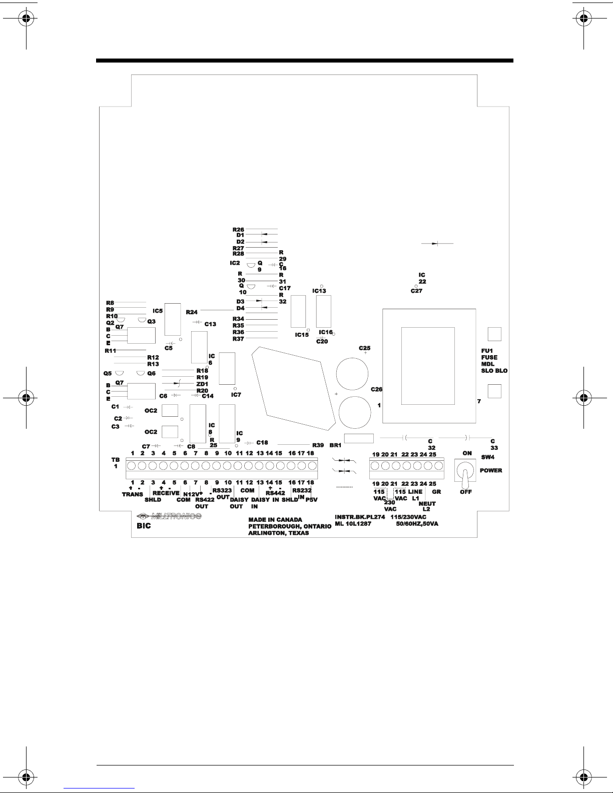
Board Layout
cvccfinal.fm Page 4 Thursday, September 6, 2001 2:17 PM
7ML19981FG01 CVCC – INSTRUCTION MANUAL Page 5
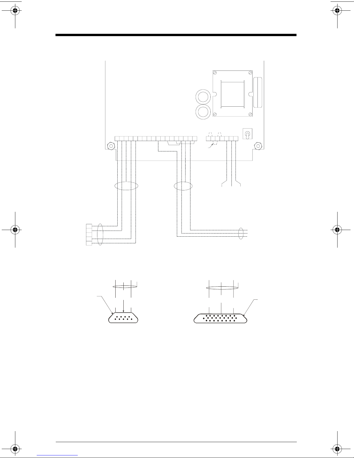
Interconnection
RS-232 Communication Format
Notes:
1. All wiring must be done in conjunction with approved conduit, boxes and fittings and
to procedures in accordance with all governing regulations.
2. All wiring to be done by customer (----). Check that jumpers 1TB-12/15 and 14/18 are
in place.
3. For CVCC 115 Vac operation, wire jumpers across TB1 terminals 19 to 20 and 21 to 22.
For 230 Vac operation, wire a jumper across TB1 terminals 20 and 21 only. Refer to
board silkscreen.
4. Refer to the associated product manuals for details on terminal connections.
Connect shield at only one end.
L
2
/G
L
-
+
-
+V
5
P
N
I
2
3
2
S
R
D
L
E
I
H
S
-
N
I
2
2
4
S
R
+
N
I
Y
S
I
A
D
M
O
C
T
U
O
Y
S
I
A
D
T
U
O
2
3
2
S
R
-
T
U
O
2
2
4
S
R
+V
2
1
N
M
O
C
E
V
I
E
C
E
R
D
L
E
I
H
S
T
I
M
S
N
A
R
T
1
V AC
230
VAC
115
VAC
115
RN1
1
2 3 4 5 6 7 8 9 10 1112 13 14 15 16 17 18 19 20 2122 23 24 25
TB1
note 3
SW 4
FUSE
3
2
7
2
35
2
O
U
T
O
U
T
I
N
I
N
C
O
M
C
O
M
S
H
L
D
S
H
L
D
L1 L2/N GR
main power
connection
Belden 9552
15 m max. run OUT
COM
IN
customer’s
computer
note 4
+
-
+
-
shld
{
{
receive
transmit
Belden 9552
DB 9
connector DB 25
connector
IBM PC Computer Connection
computer serial port (e.g. com1) computer serial port (e.g. com1)
9 PIN 25 PIN
cvccfinal.fm Page 5 Thursday, September 6, 2001 2:17 PM
Page 6 CVCC – INSTRUCTION MANUAL 7ML19981FG01
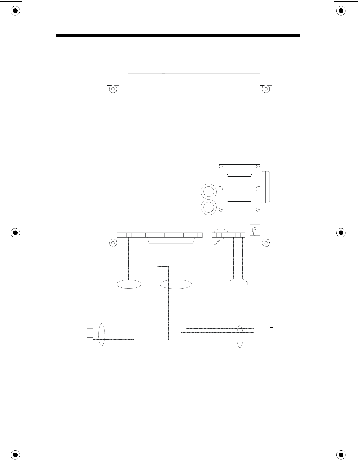
Interconnection
RS-422 Communication Format
Notes:
1. All wiring must be done in conjunction with approved conduit, boxes and fittings and
to procedures in accordance with all governing regulations.
2. All wiring to be done by customer (----). Check that jumper 1TB-7/17 is in place.
3. For CVCC 115 Vac operation, wire jumpers across TB1 terminals 19 to 20 and 21 to 22.
For 230 Vac operation, wire a jumper across TB1 terminals 20 to 21 only. Refer to
board silkscreen.
4. Refer to associated product manuals for details on terminal connections. Connect
shield at only one end.
L
2
/
LG
-
+
-
+V
5
P
N
I
2
3
2
S
R
D
L
E
I
H
S
-
N
I
2
2
4
S
R
+
N
I
Y
S
I
A
D
M
O
C
T
U
O
Y
S
I
A
D
T
U
O
2
3
2
S
R
-
T
U
O
2
2
4
S
R
+V
2
1
N
M
O
C
E
V
I
E
C
E
R
D
L
E
I
H
S
T
I
M
S
N
A
R
T
1
V AC
230
VAC
115
VAC
115
RN1
1
2 3 4 5 6 7 8 9 10 1112 13 14 1516 17 18 19 20 2122 23 24 25
TB1
note 3
SW 4
FUSE
note 4
+
-
+
-
shld
{
{
receive
transmit
Belden 9552
L1 L2/N GR
main power
connection
Belden 9553
15 m max. run OUT
IN
to customer’s
computer port
+
-
-
+
COM
OUT
IN
note 4
cvccfinal.fm Page 6 Thursday, September 6, 2001 2:17 PM

IQ300IX.fm Page 5 Tuesday, October 2, 2001 1:43 PM

IQ300IX.fm Page 5 Tuesday, October 2, 2001 1:43 PM

IQ300IX.fm Page 5 Tuesday, October 2, 2001 1:43 PM

CVCC
CURRENT VOLTAGE COMMUNICATION CONVERTER
September 2001
COMMUNICATION CONVERTER
Instruction Manual PL-370
*7ML19981FG01*
Table of contents


