Milltronics smartlinx User manual
Instruction Manual February 2004
MODBUS RTU
smartlinx interface module

© Siemens MilltronicsProcessInstruments Inc. 2004
Safety Guidelines
Warning notices must be observed to ensure personal safety as well as that of others, and to
protect the product and the connected equipment. These warning notices are accompanied
by a clarification of the level of caution to be observed.
Qualified Personnel
This device/system may only be set up and operated in conjunction with this manual.
Qualified personnel are only authorized to install and operate this equipment in accordance
with established safety practices and standards.
Warning: This product can only function properly and safely if it is correctly transported,
stored, installed, set up, operated, and maintained.
Note: Always use product in accordance with specifications.
Copyright Siemens Milltronics Process
Instruments Inc.2004.AllRights ReservedDisclaimer of Liability
This document is available in bound version and in
electronic version. We encourage users to
purchase authorized bound manuals, or to view
electronic versions as designed and authored by
Siemens Milltronics Process Instruments Inc.
Siemens Milltronics Process Instruments Inc. will
not be responsible for the contents of partial or
whole reproductions of either bound or electronic
versions.
While we have verified the contents of
this manual for agreement with the
instrumentation described, variations
remain possible. Thus we cannot
guarantee full agreement. The
contents of this manual are regularly
reviewed and corrections are included
in subsequent editions. We welcome
all suggestions for improvement.
Technical data subject to change.
MILLTRONICS®is a registered trademark of Siemens Milltronics Process Instruments Inc.
Contact SMPI Technical Publications at the following address:
Technical Publications
Siemens Milltronics Process Instruments Inc.
1954 Technology Drive, P.O. Box 4225
Peterborough, Ontario, Canada, K9J 7B1
Email: techpubs@siemens-milltronics.com
For the libraryof SMPI instruction manuals, visitour Web site: www.siemens-milltronics.com

i
Table of Contents
About this Module .......................................................................................................................................1
Typical Modbus RTU RS-485 System .................................................................................................1
Typical Modbus RTU RS-232 System .................................................................................................2
About this Manual .......................................................................................................................................3
Specifications ...............................................................................................................................................4
Installation ......................................................................................................................................................5
Compatibility .............................................................................................................................................5
Module Outline ........................................................................................................................................5
Termination Switch .................................................................................................................................6
Port Configuration ...................................................................................................................................6
Reserved Switch ......................................................................................................................................6
Cable Connection ....................................................................................................................................7
Operation .........................................................................................................................................................9
Status LEDs ...............................................................................................................................................9
Initialization LED ......................................................................................................................................9
Communications Setup ..........................................................................................................................10
General .....................................................................................................................................................10
Specific Parameters .............................................................................................................................10
Application Layer ......................................................................................................................................12
Parameter Indexes ................................................................................................................................12
How Modbus RTU Works ....................................................................................................................13
Register Mapping ..................................................................................................................................14
Data Access Methods ..........................................................................................................................15
Register Map – Level Products .........................................................................................................17
Data Types ...............................................................................................................................................21
Modbus RTU Error Codes ...................................................................................................................24
Troubleshooting ..........................................................................................................................................25
Generally .................................................................................................................................................25
Specifically ..............................................................................................................................................25
Wiring Guidelines .....................................................................................................................................26

ii

7ML19981BF01 SmartLinx Modbus RTU – INSTRUCTION MANUAL Page 1
mmmmm
About this Module
About this Module
The Milltronics SmartLinx®Modbus® RTU Module plugs into a compatible Milltronics
instrument to allow connection to any Modbus RTU master controller.
Modbus RTU is an industry standard protocol that is supported by many different
instruments. A brief description of the protocol and the Milltronics memory map are
outlined in Modbus RTU Protocol section of this manual (see page 20).
Only those instruments which support the SmartLinx Modbus RTU module can use this
card. See Specifications on page 5 for a list of compatible instruments.
Typical Modbus RTU RS-485 System
®. Modbus is a registered trademark of Schneider Electric.
mA
5
9
C
PP
6
0
78
1234

Page 2 SmartLinx Modbus RTU – INSTRUCTION MANUAL 7ML19981BF01
mmmmm
About this Module
Typical Modbus RTU RS-232 System
mA
5
9
C
PP
6
0
78
1234

7ML19981BF01 SmartLinx Modbus RTU – INSTRUCTION MANUAL Page 3
mmmmm
About this Manual
About this Manual
This manual is intended to provide the user with the information required to successfully
install and connect a Milltronics SmartLinx Modbus RTU module and set it up for
communication within a Modbus RTU network.
This manual is targeted to a technical audience in the industrial communications field
with a sound working knowledge of Modbus RTU.
Modbus RTU is an industry standard protocol owned by Schneider Electric and is used
throughout process control industries for communication between instruments, including
those manufactured by Milltronics, and controllers, such as PLCs and PCs.
A brief description of Modbus RTU is given in this manual. For a full description of the
Modbus RTU protocol, contact Schneider Electric or visit their website at
www.modicon.com.
If you have any questions, comments, or suggestions about the manual contents, please
email us at techpubs@siemens-milltronics.com.
For the complete library of Siemens Milltronics manuals,
go to www.siemens-milltronics.com.
Note: Milltronics does not own the Modbus RTU protocol. All information regarding
that protocol is subject to change without notice.

Page 4 SmartLinx Modbus RTU – INSTRUCTION MANUAL 7ML19981BF01
mmmmm
Specifications
Specifications
Application:
• compatible with Modbus RTU masters that use function codes 03, 06, 16
Compatible Instruments:
• AiRanger XPL Plus/SITRANS LU 10
• AiRanger DPL Plus/SITRANS LU 02
• AiRanger SPL/SITRANS LU 01
•CraneRanger
• InterRanger DPS 300
Communication Settings
• baud rate: 1200, 2400, 4800, 9600, 19200, 38400 bps
• parity: none, odd or even
• stop bit: 1 or 2
• data bits: 8
• hardware flow control: none
Connection:
• 6-position screw terminal
Termination:
• RS-485 switch selectable, open or 110 Ωinternal
Cable:
• for RS-232 connection use cable consistent with the RS-232 standard
• for RS-485 connection use cable consistent with the RS-485 standard
(see Wiring Guidelines on page 26 for more suggestions)
7ML19981BF01 SmartLinx Modbus RTU – INSTRUCTION MANUAL Page 5
mmmmm
Installation
Installation
The SmartLinx module may have been shipped installed in your unit, or separately for
onsite installation. Refer to the manual for the Milltronics SmartLinx instrument for
details on module location and physical installation.
Compatibility
AiRanger Series
• AiRanger XPL Plus/SITRANS LU 10
• AiRanger DPL Plus/SITRANS LU 02
• AiRanger SPL/SITRANS LU 01
•CraneRanger
• InterRanger DPS 300
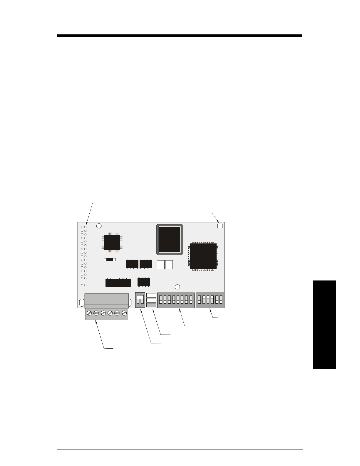
Module Outline
module connector (underside) to
Milltronics instrument initialization LED
cable connector
to host
1.6 m
termination switch
status LEDs
reserved
port configuration
Page 6 SmartLinx Modbus RTU – INSTRUCTION MANUAL 7ML19981BF01
mmmmm
Installation
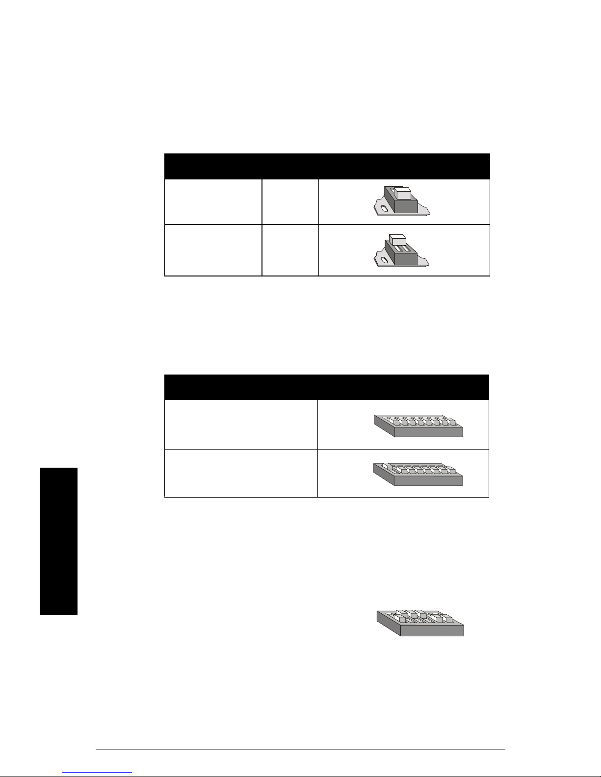
Termination Switch
Termination is generally of concern when communicating at higher baud rates, and when
the Milltronics host instrument is the unique or terminating slave.
If the 110 Ωswitched termination is inappropriate, set the switch to open and connect an
appropriate resistor across terminals 4 and 5.
Port Configuration
Switch one configures the port for either RS-232 or RS-485 transmission.
Reserved Switch
These switches are reserved and must be left in their factory setting.
termination setting
open off
110 Ωon
transmission dip switches
RS-232
RS-485
ON
18
ON
18
ON
16
Other manuals for smartlinx
1
Table of contents
Other Milltronics Recording Equipment manuals


