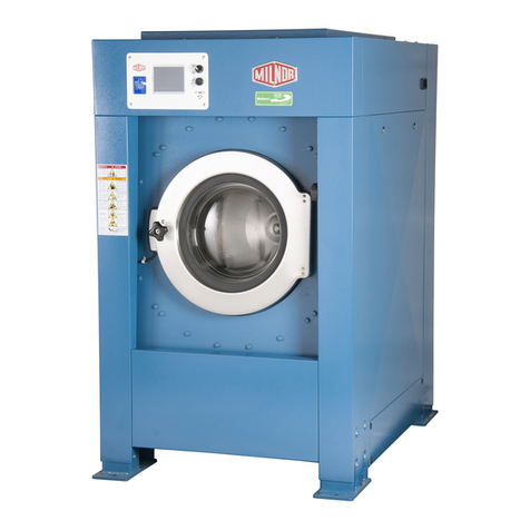
Milnor E-P Plus Service manual

PELLERIN MILNOR CORPORATION Post Office Box 400, Kenner, Louisiana 70063–0400, U.S.A.
Controller Reference
Using the E-P Plus®
Control on MWF_,
MWR_ & MWT_
Models
Manual Number: MCCJUB01
Edition (ECN): 2020434


Pellerin Milnor Corporation i
Contents
Preface ..............................................................................................................................................1
1 About This Manual................................................................................................................1
1.1 Scope ..........................................................................................................................1
1.2 The Normal Display at Start-up ................................................................................1
1.3 If this Manual Does Not Have the Necessary Data ....................................................1
1.4 Trademarks .................................................................................................................1
1 Commissioning..............................................................................................................................3
1.1 Important Data About this Machine ..................................................................................3
1.1.1 Make Sure That All Laundry Personnel are Safe ....................................................3
1.1.2 Change the Data ......................................................................................................3
1.1.2.1 When to Change Data...................................................................................3
1.1.2.2 Steps that are Necessary When You Change Data .......................................4
1.1.2.3 Data Accessibility.........................................................................................4
1.1.2.4 Replace Incorrect Data .................................................................................4
1.2 Determining Load Size ......................................................................................................4
1.3 Vital Information About the Forces Imparted to Supporting Structures by Launder-
ing Machines ...........................................................................................................5
1.3.1 Disclaimer of Responsibility ...................................................................................5
1.3.2 Major Design Considerations ..................................................................................5
1.3.3 Primary Information Sources ..................................................................................6
1.4 Prevent Damage from Chemical Supplies and Chemical Systems ...................................7
1.4.1 How Chemical Supplies Can Cause Damage..........................................................7
• Dangerous Chemical Supplies and Wash Formulas..............................................7
• Incorrect Configuration or Connection of Equipment ..........................................7
1.4.2 Equipment and Procedures That Can Prevent Damage...........................................9
• Use the chemical manifold supplied. ....................................................................9
• Close the line.......................................................................................................10
• Do not let a vacuum occur...................................................................................10
• Flush the chemical tube with water.....................................................................10
• Put the chemical tube fully below the inlet.........................................................10
• Prevent leaks. ......................................................................................................10
2 Programming ...............................................................................................................................14
2.1 Controls on E-P Plus®Washer-extractors .......................................................................14
2.1.1 Control Functions During Normal Operation........................................................15
2.1.2 Control Functions During Manual Operation........................................................17
2.1.3 Control Functions During Programming...............................................................18
2.2 Selecting an Industry Formula Set ..................................................................................18
2.3 Programming the E-P Plus®Controller ...........................................................................20
2.3.1 How to Avoid Data Loss .......................................................................................21
2.3.2 Return to Run Mode (Option 0) ............................................................................21
2.3.3 How to Add or Change a Formula (Option 1).......................................................22
2.3.3.1 What are Formulas, Steps, and Decisions? ................................................22
2.3.3.2 About the Help Screens ..............................................................................22
2.3.3.3 Moving Forward and Backward through Steps and Decisions ..................23
2.3.3.3.1 Actions when the Cursor is at the Step Number..............................23
2.3.3.3.2 Actions when the Cursor is at a Decision within a Step..................23
ii Pellerin Milnor Corporation
2.3.3.4 Create a New Formula................................................................................24
2.3.3.5 Delete an Existing Formula ........................................................................24
2.3.3.6 Change an Existing Formula ......................................................................25
2.3.3.6.1 How to Insert or Delete a Step in an Existing Formula...................25
2.3.3.6.1.1 Inserting a Step .....................................................................25
2.3.3.6.1.2 Deleting a Step .....................................................................25
2.3.3.6.2 The Step Decisions ..........................................................................26
2.3.3.6.2.1 How to Modulate Water Valves to Regulate Incoming
Water Temperature .................................................................29
2.3.3.6.3 How to Use Cooldown ....................................................................29
2.3.3.6.4 How to Select the Bath Level..........................................................30
2.3.3.6.5 How to Select the Steam Code ........................................................31
2.3.3.6.6 Injecting Chemicals .........................................................................32
2.3.3.6.7 Concluding Decisions......................................................................34
2.3.3.6.8 How to Save or Discard Changes....................................................40
2.3.4 Configure the Control (Option 2) ..........................................................................40
2.3.4.1 Moving Forward and Backward in Configure ..........................................41
2.3.4.2 The Configure Decisions............................................................................41
2.3.5 Restoring the Standard Formulas ..........................................................................45
2.3.5.1 Chart 1: Restore Standard Formulas (Part A).............................................45
2.3.5.2 Part B ..........................................................................................................46
2.3.5.3 Part C ..........................................................................................................46
2.3.5.4 Restoring the Standard Formulas on Models Employing the Milnor®
E-P Plus®and E-P Express®Controller .................................................47
2.3.6 Data Transfer (Option 4) .......................................................................................48
2.3.6.1 Establishing the Required Connections......................................................49
2.3.6.2 Saving Data from the Machine to the Storage Device or a Second
Machine ..................................................................................................50
2.3.6.3 Restoring Saved Data to the Machine from the Storage Device or An-
other Machine.........................................................................................52
3 Operating .....................................................................................................................................55
3.1 Running a Formula ..........................................................................................................55
3.1.1 Applying Power.....................................................................................................55
3.1.2 Selecting and Starting the Formula .......................................................................55
3.2 How to Use and Erase the Formula Counter ...................................................................60
4 Troubleshooting...........................................................................................................................61
4.1 The E-P Plus®Manual Menu ..........................................................................................61
4.1.1 The Manual Menu................................................................................................61
4.1.1.1 Components................................................................................................61
4.1.1.2 How to Access the Manual Menu ............................................................61
4.1.1.3 How to Return to the Run Mode from the Manual Menu .......................62
4.1.2 Determining the Software Version ........................................................................62
4.1.3 Viewing Microprocessor Inputs ............................................................................63
4.1.4 Actuating Microprocessor Outputs........................................................................64
4.1.5 Testing and Verifying the DIP Switch Settings .....................................................66
4.1.6 Testing Temperature and Level Sensors................................................................68
4.1.6.1 Testing the Pressure Transducer Circuit.....................................................70
Contents

Pellerin Milnor Corporation iii
4.1.7 Viewing Inputs and Outputs During Operation.....................................................71
4.1.8 Viewing Water Level and Temperature Data During Operation ...........................72
4.2 Error Messages ................................................................................................................72
4.2.1 Error Messages at Power Up .................................................................................72
4.2.2 Error Messages during Normal Operation ............................................................73
5 Supplemental Information ...........................................................................................................76
5.1 The E-P Plus®and E-P Express®Hardware ....................................................................76
5.1.1 Keyswitches...........................................................................................................76
5.1.1.1 Run/Program Keyswitch ............................................................................76
5.1.1.2 Automatic/Test Keyswitch (E-P Plus®Models Only)................................76
5.1.2 Display...................................................................................................................76
5.1.3 Power Supply.........................................................................................................76
5.1.4 CPU Processor Board ............................................................................................77
5.1.5 Outputs ..................................................................................................................77
5.1.6 Option Outputs (E-P Plus®Models Only).............................................................78
5.1.7 Temperature Probe (E-P Plus®Models Only).......................................................78
5.1.8 Pressure Sensor (E-P Plus®Models Only) ............................................................78
5.2 Serial Memory Storage Device Applications ..................................................................78
5.3 Construction of External Serial Link Cables ...................................................................80
5.3.1 Pin Identification ...................................................................................................81
5.3.2 How to Wire the Cables.........................................................................................82
5.3.2.1 Cable Specifications ...................................................................................82
5.3.2.2 Connecting Two or More Machines for Machine-to-machine
Transfer...................................................................................................82
5.3.2.3 Connecting a Machine to a Serial Memory Storage Device ......................83
5.4 Printer Requirements and Settings ..................................................................................84
5.4.1 Cable Requirements...............................................................................................84
5.4.2 Configuring the Citizen GSX-190 Printer.............................................................85
5.4.3 Configuring the Epson LX300 Printer ..................................................................85
5.4.4 Previous Printer Models ........................................................................................86
Figures
Figure 1 How Rotating Forces Act On the Foundation ............................................................6
Figure 2 Incorrect Configurations That Let the Chemical Supply Go In the Ma-
chine by a Siphon........................................................................................................8
Figure 3 Incorrect Configurations That Let the Chemical Supply Go In the Ma-
chine by Gravity..........................................................................................................9
Figure 4 Examples of Manifolds for Chemical Tubes. Your equipment can look
different.......................................................................................................................9
Figure 5 A Configuration that Prevents Flow in the Machine When the Pump is
Off (if the chemical tube and tank have no pressure) ...............................................10
Figure 6 Typical Control Panels..............................................................................................15
Figure 7 Location of DIP Switches .......................................................................................19
Figure 8 Controls Identification on Serial Memory Storage Device ......................................49
Figure 9 Processor Board ........................................................................................................66
Figure 10 Level Sensor Testing Fixture ....................................................................................69
Figure 11 Pressure Transducer Component Identification........................................................71
Contents

iv Pellerin Milnor Corporation
Figure 12 Serial Memory Storage Device.................................................................................79
Figure 13 Rear View of Circuit Board ......................................................................................79
Figure 14 9-Pin DIN Connector Pin Identification (from wire entry side of
connectors)................................................................................................................81
Figure 15 Wiring Diagram for Cable to Connect Two or More Machines ...............................83
Figure 16 Wiring Diagram for Cable to Connect a Machine to a Serial Memory
Storage Device..........................................................................................................84
Tables
Table 1 Trademarks ................................................................................................................2
Table 2 How to Read and Change Data ..................................................................................4
Table 3 Chemical Injection Signals for H_J, X_J, and 30-inch V_J Models .......................13
Table 4 DIP Switch Settings for Industry Configurations ....................................................20
Table 5 Summary of E-P Plus Steam Code Choices ............................................................32
Table 6 Codes for Inject Times of 100 Seconds and Longer ................................................33
Table 7 Summary of Drain Type Choices .............................................................................35
Table 8 Summary of Choices for Ending a Formula (software versions WUV7J1B/
2300P and later or WUH7JA/2200Z and later) .......................................................38
Table 9 Recommended Water Levels ...................................................................................43
Table 10 Controllers Capable of Transferring Memory .........................................................48
Table 11 Coast Times (in seconds) at Program End or Termination ......................................56
Table 12 E-P Plus Inputs .........................................................................................................63
Table 13 E-P Plus Outputs ......................................................................................................65
Table 14 Interpretation of Test DIP Switch Display .............................................................67
Table 15 DIP Switch Positions for E-P Plus®and E-P Express®Machines (External
transmit button required) .........................................................................................80
Table 16 External Serial Link Pin Assignments .....................................................................81
Table 17 Milnor Printer Cables ...............................................................................................84
Table 18 Required Settings for Citizen GSX-190 Printer ......................................................85
Table 19 Required Settings for Epson LX300 Printer ............................................................85
Contents

Preface
BNWCUD02 / 2018256 BNWCUD02 0000189783 C.3 1/2/20 2:19 PM Released
1About This Manual
1.1 Scope
BNWCUD02.C02 0000189781 C.2 C.3 B.2 1/2/20 2:19 PM Released
This manual tells how to start, program, operate, and repair washer-extractors with the Milnor®
E-P Plus®microprocessor control. See the installation manual for installation procedures and me-
chanical requirements. See the maintenance manual for maintenance and repair procedures and to
identify parts. See the schematic manual for electrical parts and electrical repair instructions.
1.2 The Normal Display at Start-up
BNWCUD02.C03 0000189780 C.2 C.3 A.6 1/2/20 2:19 PM Released
The start-up display sequence for the E-P Plus controller is described in 3.1: Running a Formula,
page 55 .
1.3 If this Manual Does Not Have the Necessary Data
BNUUUU03.C01 0000188801 C.2 C.3 B.4 1/2/20 2:14 PM Released
This manual has the best data that was available when your machine was made. If you cannot find
the necessary data:
•Are you looking for data about a component not made by Milnor®but used on your ma-
chine—for example, a motor or a brake caliper? We usually do not put the instructions of
component manufacturers in Milnor®manuals. You can find some of these instructions in the
part of the Milnor®website that gives maintenance data (http://milnortechnicalsupport.force.
com/pkbmilnor/). You can also find instructions for many components on the manufacturers’
websites.
•Are you looking for data about a Milnor®component on your machine that this manual
does not give? If we get better data or more data after the manual is available, we will add it
to a newer version of the manual. Speak with the Milnor®Customer Support group. They can
give you newer instructions if they are available or help you if not.
1.4 Trademarks BNUUUU02.R01 0000158093 C.2 C.3 D.2 4/6/20 2:44 PM Released
These words are trademarks of Pellerin Milnor®Corporation and other entities:
Pellerin Milnor Corporation 1

2Pellerin Milnor Corporation
Table 1. Trademarks
AutoSpot™ GreenFlex™ MilMetrix®PulseFlow®
CBW®GreenTurn™ MilTouch™ Ram Command™
Drynet™ Hydro-cushion™ MilTouch-EX™ RecircONE®
E-P Express®Mentor®MILRAIL™ RinSave®
E-P OneTouch®Mildata®Miltrac™ SmoothCoil™
E-P Plus®Milnor®PBW™ Staph Guard®
Gear Guardian®
Preface

1 Commissioning
BNWCUD03 / 2018256 BNWCUD03 0000189806 A.6 1/2/20 2:19 PM Released
1.1 Important Data About this Machine
BNWCUD03.T01 0000189805 C.2 A.6 1/2/20 2:19 PM Released
Complete these two procedures before you use this machine:
1. Make sure that all laundry personnel are safe.
2. Change and make a check of the data contained in the memory of the machine (configuration,
formulas, and formula accumulator data).
1.1.1 Make Sure That All Laundry Personnel are Safe
BNWCUD03.C01 0000189804 C.2 A.6 1/2/20 2:19 PM Released
Personnel who will use or do maintenance on this machine must read the safety manual first.
Make all user manuals available to the correct personnel. Be sure that all personnel obey all pre-
cautions in the applicable manuals.
1.1.2 Change the Data
BNWCUD03.C02 0000189803 C.2 A.6 1/2/20 2:19 PM Released
1. Make sure that the controller configuration is correct for how you will use the machine.
2. Change the wash formulas if necessary for better results.
3. Make sure that you erased the formula count accumulator to make the formula count
accurate.
1.1.2.1 When to Change Data
BNWCUD03.C03 0000189802 C.2 A.6 1/2/20 2:19 PM Released
Make a check of the data:
• when commissioning the machine
• when required by error message
• after replacing the microprocessor board
• after upgrading the software
• after adding or removing optional equipment
Make the necessary changes.
Pellerin Milnor Corporation 3

4Pellerin Milnor Corporation
1.1.2.2 Steps that are Necessary When You Change Data
BNWCUD03.T02 0000189801 C.2 A.6 1/2/20 2:19 PM Released
1. Make a check of the machine configuration.
2. Write wash formulas.
3. Erase the formula accumulator data, if applicable. See the applicable sections in this manual
for instructions.
1.1.2.3 Data Accessibility
BNWCUD03.C04 0000189816 C.2 A.6 B.3 1/2/20 2:19 PM Released
The key switch must be in the Program position to change configuration and formula data. The
microprocessor controller changes the formula accumulator data while the machine operates.
Thus, the key switch can not prevent changes to the accumulator data. You can use the data as
given in Table 2 .
Table 2. How to Read and Change Data
Data Type How to Change Data
Configuration Data You can read and change data.
Formula Data You can read, change, and erase data.
Accumulator Data You can read and erase data.
1.1.2.4 Replace Incorrect Data
BNWCUD03.C05 0000189826 C.2 A.6 1/2/20 2:19 PM Released
If the microprocessor finds incorrect data, the display will show an error message, usually when
the machine first gets power. The error can prevent machine operation. The troubleshooting in-
structions tell about each error and how to repair it. Obey these instructions to make sure that in-
correct data is replaced with correct data. You can cause dangerous operation or damage to the
machine if you do not obey these instructions.
BNWUUO01 / 2018153A BNWUUO01 0000181431 A.3 1/2/20 2:19 PM Released
1.2 Determining Load Size
BNWUUO01.C01 0000181430 C.2 A.3 B.3 1/2/20 2:19 PM Released
You will not do damage to the machine with a large load if you follow these rules:
1. The goods are made of common cotton or synthetic materials.
2. The load can balance in the cylinder before the extract step.
3. The extract speed has not been increased above the designed maximum.
4. You do not program so many extract steps that you do damage to the motor.
For common goods, the size of the machine sets the quantity you can put in the machine.
These items determine the maximum load weight of soiled goods:
• the volume of the machine's cylinder, and
• the material and weight of the goods.
Commissioning

Pellerin Milnor Corporation 5
Do not try to load the machine to its maximum weight capacity with bulky fabrics.
Use the size of the machine, the type of the goods, the amount of soil, and the wash quality when
you load the machine.
BNUUUI01 / 2019392 BNUUUI01 0000189337 C.3 1/2/20 2:14 PM Released
1.3 Vital Information About the Forces Imparted to Sup-
porting Structures by Laundering Machines
BNUUUI01.C01 0000189336 C.2 C.3 A.5 1/2/20 2:14 PM Released
This document replaces Milnor®document BIWUUI02.
All laundering machines impart static and dynamic forces to the supporting structures (foundation
and soil, floor, and building). Static forces include the machine weight plus the weight of the
goods and water. Dynamic forces are those imparted by various machine movements as explained
in 1.3.2: Major Design Considerations, page 5 . The dynamic forces imparted to supporting struc-
tures can cause vibration and noise outside of the laundry room if supporting structures are
inadequate.
1.3.1 Disclaimer of Responsibility
BNUUUI01.C02 0000189359 C.2 C.3 B.3 1/2/20 2:14 PM Released
Pellerin Milnor Corporation accepts no responsibility for damage or loss as a result of:
• inadequate supporting structures
• interference with the use of the facility caused by machine operation
The facility owner/operator is solely responsible to ensure that:
• supporting structures are strong enough, with a reasonable safety factor, to safely support the
operating machine or group of machines
• supporting structures are rigid enough to isolate vibrations and noise to the laundry room
If the owner/operator does not possess the necessary expertise to ensure that the facility can safely
and functionally accommodate the equipment, it will be necessary to consult the appropriate ex-
pert(s), such as a structural engineer, soils engineer, and/or architect.
1.3.2 Major Design Considerations
BNUUUI01.C03 0000189358 C.2 C.3 A.5 1/2/20 2:14 PM Released
• Vibration and/or noise can be felt or heard outside of the laundry room as a result of the fol-
lowing, if supporting structures are not sufficiently rigid:
– Extraction (the spinning cylinder) in washer-extractors and centrifugal extractors, imparts
sinusoidal forces to supporting structures as shown in Figure 1: How Rotating Forces Act
On the Foundation, page 6 . In rigid washer-extractors, these forces are up to 30 times that
of suspended washer-extractors of the same capacity.
– Extraction forces can be magnified many times if the rotation frequency matches the reso-
nant frequency of supporting structures. To avoid this, supporting structures must have a
Commissioning

6Pellerin Milnor Corporation
natural resonant frequency many times greater than any possible rotation speed of the ma-
chine or combination of rotation speeds of all machines.
– Each time goods fall in the rotating cylinder of a washer, washer-extractor, centrifugal ex-
tractor, or dryer, this can impart a force to the supporting structures.
– The intermittent start and stop actions of large components inside the machine, particu-
larly in a tilting washer-extractor, press-extractor, or centrifugal extractor, can impart in-
termittent forces to the supporting structures.
• The possibility of adverse consequences is significantly greater for upper floor installations
than for installations at grade. Always consult a structural engineer for such an installation.
• The possibility of adverse consequences is significantly greater for installations at grade if
subsidence causes a void between the foundation and the soil or if the soil itself does not pro-
vide adequate strength and rigidity. Some possible remedies are the addition of pilings or a
deeper foundation, installed as to be monolithic with the existing foundation.
• Machine forces can cause damage to the machine or the floor without the correct anchorage.
• Applicable building codes, even when met, do not guarantee sufficient structural support and
isolation of machine forces to the laundry room.
Figure 1. How Rotating Forces Act On the Foundation
Typical Washer-extractor (see note below)
Legend
A...Direction of force
B...Load
C...Rotation (frequency = RPM / 60)
NOTE: This figure applies to both rigid and suspended washer-extractors and to both
at-grade and upper floor installations.
1.3.3 Primary Information Sources
BNUUUI01.C04 0000189357 C.2 C.3 A.5 1/2/20 2:14 PM Released
Milnor®provides, or can provide the following information of use to engineers and architects, for
the given machine model:
• The machine dimensional drawing, found in the installation manual, specifies the machine’s
required anchorage.
• The Milnor®Service Department can provide static and dynamic load values and frequency
(extract speed) values on request.
Commissioning

Pellerin Milnor Corporation 7
NOTICE: All data is subject to change without notice and may have changed since last
printed. It is the responsibility of the potential owner/operator to obtain written confirma-
tion that any data furnished by Milnor®applies for the model number(s) and serial num-
ber(s) of the purchased machine(s).
BIWUUI03 / 2019296 BNUUUR02 0000160550 E.3 1/2/20 2:14 PM Released
1.4 Prevent Damage from Chemical Supplies and
Chemical Systems
BNUUUR02.C01 0000160549 C.2 E.3 B.3 1/2/20 2:14 PM Released
All Milnor®washer-extractors and CBW®tunnel washers use stainless steel with the ANSI 304
specification. This material gives good performance when chemical supplies are correctly ap-
plied. If chemical supplies are incorrectly applied, this material can be damaged. The damage can
be very bad and it can occur quickly.
Chemical supply companies usually:
• supply chemical pump systems that put the supplies in the machine,
• connect the chemical pump system to the machine,
• write wash formulas that control the chemical concentrations.
The company that does these procedures must make sure that these procedures do not cause dam-
age. Pellerin Milnor Corporation accepts no responsibility for chemical damage to the ma-
chines it makes or to the goods in a machine.
1.4.1 How Chemical Supplies Can Cause Damage
BNUUUR02.R01 0000160548 C.2 E.3 B.4 1/2/20 2:14 PM Released
Dangerous Chemical Supplies and Wash Formulas — Some examples that
can cause damage are:
• a very high concentration of chlorine bleach,
• a mixture of acid sour and hypo chlorite,
• chemical supplies (examples: chlorine bleach, hydrofluosilicic acid) that stay on the stainless
steel because they are not quickly flushed with water.
The book “Textile Laundering Technology” by Charles L. Riggs gives data about correct chemi-
cal supplies and formulas.
Incorrect Configuration or Connection of Equipment — Many chemical
systems:
• do not prevent a vacuum in the chemical tube (for example, with a vacuum breaker) when the
pump is off,
• do not prevent flow (for example, with a valve) where the chemical tube goes in the machine.
Damage will occur if a chemical supply can go in the machine when the chemical system is off.
Some configurations of components can let the chemical supplies go in the machine by a siphon
Commissioning

8Pellerin Milnor Corporation
(Figure 2: Incorrect Configurations That Let the Chemical Supply Go In the Machine by a Si-
phon, page 8 ). Some can let chemical supplies go in the machine by gravity (Figure 3: Incorrect
Configurations That Let the Chemical Supply Go In the Machine by Gravity, page 9 ).
Figure 2. Incorrect Configurations That Let the Chemical Supply Go In the Machine by a Siphon
Schematic Views
Legend
P...Pump
T...Chemical tank
S...The siphon occurs above here. Liquid in the gray parts of the chemical tube and tank can go in the machine.
Commissioning

Pellerin Milnor Corporation 9
Figure 3. Incorrect Configurations That Let the Chemical Supply Go In the Machine by Gravity
Schematic Views
Legend
P...Pump
T...Chemical tank
D...Chemical tube. Liquid in the gray areas can go in the machine.
1.4.2 Equipment and Procedures That Can Prevent Damage
BNUUUR02.R02 0000160545 C.2 E.3 B.3 1/2/20 2:14 PM Released
Use the chemical manifold supplied. — There is a manifold on the machine to at-
tach chemical tubes from a chemical pump system. The manifold has a source of water to flush
the chemical supplies with water.
Figure 4. Examples of Manifolds for Chemical Tubes. Your equipment can look different.
Commissioning

10 Pellerin Milnor Corporation
Close the line. — If the pump does not always close the line when it is off, use a shutoff
valve to do this.
Do not let a vacuum occur. — Supply a vacuum breaker in the chemical line that is
higher than the full level of the tank.
Flush the chemical tube with water. — If the liquid that stays in the tube between
the pump and the machine can flow in the machine, flush the tube with water after the pump
stops.
Put the chemical tube fully below the inlet. — It is also necessary that there is no
pressure in the chemical tube or tank when the system is off.
Figure 5. A Configuration that Prevents Flow in the Machine When the Pump is Off (if the chemical
tube and tank have no pressure)
Schematic View Legend
I...Chemical inlet on the machine
L...Chemical tube
P...Pump
T...Chemical tank
Prevent leaks. — When you do maintenance on the chemical pump system:
• Use the correct components.
• Make sure that all connections are the correct fit.
• Make sure that all connections are tight.
BNCJVI01 / 2018385 BNCJVI01 0000181453 D.5 1/2/20 1:16 PM Released
1.5 Connecting Chemical Systems
BNCJVI01.C01 0000181452 C.2 D.5 C.3 1/2/20 1:16 PM Released
Multiple methods are available on E-P Plus®washer-extractors to accommodate chemical sys-
tems. Use this section to help determine the best method of chemical injection and how to connect
the chemical system. Always consult the schematic manual for this machine before connecting
chemical systems to the machine.
Commissioning

Pellerin Milnor Corporation 11
DANGER: Electric Shock Hazard — Contact with high voltage electricity will kill
or seriously injure you. Even with the Master Switch off and/or any
Emergency Stop switches off, three-phase power and control circuit
power are still present at several locations within electric boxes and electri-
cal components.
DANGER: Injury and Damage Hazards — Improper wiring can cause the machine
to malfunction, risking injury to personnel, damage to machine compo-
nents, and damage to goods.
�Electrical and piping connections described in this section must be
made only by qualified, authorized personnel.
�Lock off and tag out power at the external disconnect switches for the
washer-extractor and for any chemical devices that provide power to the interpret relay
box (if furnished) before proceeding.
�Do not rely merely on the information in this section when wiring. Consult all applica-
ble electrical schematics.
�Do not reroute or rearrange any wires not specifically permitted by this instruction.
�Do not connect a common wire to ground. Use the common terminal furnished.
CAUTION: Risk of Poor or Inconsistent Wash Quality — Injection times of less
than 10 seconds are discouraged because fine adjustments are not possible
and factors such as pump lag time may cause significant variations in the
amount of chemical delivered.
�Size pumps or valves small enough for adequate control (i.e., for lon-
ger injection times).
�Use two pumps or valves to inject a small or large quantity of the same
chemical, if required.
1.5.1 Maximizing Chemical Injection Precision
BNCJVI01.R01 0000181451 C.2 D.5 B.3 1/2/20 1:16 PM Released
Injection of a consistent amount of chemical is important in controlling wash quality and using
chemicals economically. When chemicals are injected by units of time, as is done with most
washer-extractors, injections of short duration can be imprecise because of two reasons:
• Fine adjustments to the delivered quantity are not possible. For example, if an injection of
three seconds is extended by one second, the quantity delivered is theoretically increased by
more than 30 percent. However, if an injection of 20 seconds is increased by one second, the
theoretical quantity is increased by only five percent.
• Variations in the time between the start of the chemical signal and the start of the chemical de-
livery into the machine can cause significant differences in the quantity of chemical injected.
In this case, if a pump starts more slowly some times than others, or if the delivery tubes are
partially empty at the start of the inject period, the quantity of chemical delivered may vary
significantly. As an example, assume a peristaltic pump moves chemical along the delivery
tube at a rate of three feet per second. If the delivery tube is empty for three feet along its
Commissioning

12 Pellerin Milnor Corporation
length, then one second of the injection time is spent injecting air rather than chemical. If the
programmed injection time is only three seconds, then one third of the desired chemical is not
being delivered. However, if the programmed injection time is 20 seconds, the chemical de-
livery is only five percent less than desired.
• Increasing the programmed injection time makes any variation less significant. Use pumps
and/or valves sized to allow inject times of at least 10 seconds. If injection times for a specific
chemical vary widely from one formula to another, consider using two pumps or valves for
the same chemical. Actuate one pump for injecting small quantities, and use both pumps or
valves for larger quantities.
1.5.2 Available Chemical Injection Methods
BNCJVI01.C02 0000181450 C.2 D.5 B.3 1/2/20 1:16 PM Released
All machine models are equipped with a chemical chute for the introduction of dry chemical sup-
plies directly into the bath liquor. Automatic or manual flushing is provided on most models to re-
duce the risk of corrosion. One or more other chemical injection devices, described below, are
available according to machine model.
1.5.2.1 Chemical Injection Output Signals
BNCJVI01.R02 0000181449 C.2 D.5 B.3 1/2/20 1:16 PM Released
Five discrete signals (for chemicals 1 through 5) are furnished standard on all washer extractors.
These signals are available at a terminal strip on all E-P Plus® machines. Check the nameplate
on the machine to verify the model.
Starting with E-P Plus software version WUH7JA/2200N, Milnor provides six discrete chemical
signals on H_J and X_J washer-extractors. The sixth chemical signal is between MTA3-1 (com-
mon) and MTA3-10.
1.5.2.2 Optional Five-Compartment Flushing Chemical Injector
BNCJVI01.C03 0000181448 C.2 D.5 B.3 1/2/20 1:16 PM Released
An externally mounted five-compartment dry supply injector is offered as an option on some
models. The five electrically operated flush valves are wired to chemical injection output signals
at a terminal strip on the machine (usually terminal strip TBA).
1.5.2.3 Liquid Chemical Tube Connectors
BNCJVI01.R03 0000181447 C.2 D.5 B.3 1/2/20 1:16 PM Released
A five or six port liquid chemical inlet manifold is standard equipment on most models. Use these
valveless inlets to connect tubes from remote chemical supply injection systems that are not con-
tinuously pressurized and that deliver chemicals only when an injection is commanded.
1.5.3 Considerations for Pumped Chemical Systems
BNCJVI01.C04 0000181446 C.2 D.5 C.3 1/2/20 1:16 PM Released
Pumped chemical systems deliver chemicals to the machine intermittently usually via peristaltic
pumps. Inlets on the machine must be unrestricted at all times (valveless). The supplied pumped
chemical inlets meet this requirement.
Commissioning

Pellerin Milnor Corporation 13
An inherent risk of this method of chemical injection is that concentrated chemicals can dribble
into the machine after it is shut down for the evening, causing machine and/or linen damage. Be-
cause Milnor®has no control over the design or installation of pumped chemical systems, Pellerin
Milnor Corporation accepts absolutely no responsibility for damage to its equipment or textiles
therein caused in this way. Much more information on this subject is provided in 1.4: Prevent
Damage from Chemical Supplies and Chemical Systems, page 7 . Consult this document before
connecting a pumped chemical system.
1.5.4 Connecting Devices to Receive Injection Signals
BNCJVI01.R04 0000181445 C.2 D.5 B.3 1/2/20 1:16 PM Released
For 36-inch and 42-inch V_J models, injection signals provide either 110VAC/50Hz or 120VAC/
60Hz potential. For 30-inch V_J and all F_J/F_B, H_J, and X_J models, injection signals provide
either 220VAC/50Hz or 240VAC/60Hz potential. Each signal can accomodate one apparatus not
exceeding 37 milliamperes. Inject signals cannot be made potential-free.
CAUTION: Avoid Component Damage — Board components will burn out and re-
quire board replacement if devices driven by inject signals do not meet the
electrical specifications. Pumps generally draw a higher current and will
burn out board components.
1.5.5 Connecting Chemicals to H_J, X_J, and 30-inch V_J
Models BNCJVI01.R05 0000181444 C.2 D.5 B.3 1/2/20 1:16 PM Released
Acquire signals at connector TBS near the rear access panel, next to the incoming power connec-
tions. See the following table for connection details.
Table 3. Chemical Injection Signals for H_J, X_J, and 30-inch V_J Models
Signal
Component Chemical Relay
Processor Board
Connection
Terminal
Number
Chemical 1 Detergent CR01M M5-3 95
Chemical 2 Bleach CR02M M5-6 93
Chemical 3 Sour CR03M M5-5 91
Chemical 4 Softener CR04M M5-4 75
*Chemical 5 Starch CR05M M5-2 85
**Chemical 6 —CR06M M3-10
Common all — — 6
* Chemical 5 is not used if the machine is equipped and configured for ChemSave. In this case,
relay CR05M closes whenever the machine desires to inject a chemical.
** Chemical 6 is available only on H_J and X_J models with version software WUH7JA/2200N
or later.
Commissioning

14 Pellerin Milnor Corporation
2 Programming
BNCJHP01 / 2018263 BNCJHP01 0000189822 A.5 1/2/20 1:16 PM Released
2.1 Controls on E-P Plus®Washer-extractors
BNCJHP01.C01 0000189823 C.2 A.5 1/2/20 1:16 PM Released
The controls on these Milnor®washer-extractors include push-buttons, some of which include in-
dicator lights. Some of these controls operate differently in the three machine modes. This docu-
ment gives the function of each control in the different machine modes.
Table of contents
Other Milnor Controllers manuals

Milnor
Milnor MilTouch-EX Manual

Milnor
Milnor 30010CGE User manual

Milnor
Milnor Milnor Phase 7.2.2 User manual

Milnor
Milnor MilTouch User manual

Milnor
Milnor MilTouch Manual

Milnor
Milnor MilTouch MWF27Z8 Series Manual

Milnor
Milnor MilTouch MWF27Z8 Series Manual

Milnor
Milnor E-P Express User manual

Milnor
Milnor MilTouch User manual

Milnor
Milnor Miltrac Use and care manual