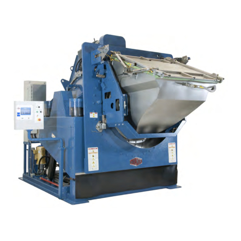
Milnor MilTouch User manual

PELLERIN MILNOR CORPORATION Post Office Box 400, Kenner, Louisiana 70063–0400, U.S.A.
Controller Reference
MilTouch™ Single-
Stage Press
Manual Number: MCP1UB01
Edition (ECN): 2021272


Pellerin Milnor Corporation i
Contents
1 Preface ...........................................................................................................................................5
1.1 About the MilTouch™ Single Stage Press Controller .......................................................5
1.1.1 The MilTouch™ Press Hierarchy of Displays ........................................................6
1.1.2 Manufacturer Data for Non-Milnor®Machine Components ..................................7
1.1.3 How to Contact Milnor®..........................................................................................8
1.2 Safety Alert for Owners/Managers and Maintenance Personnel: Using the Door In-
terlock Bypass Key Switch ......................................................................................9
2 Configuration...............................................................................................................................10
2.1 Machine Configuration ....................................................................................................10
2.1.1 The Program Menu Display ..................................................................................11
2.1.1.1 The Configure Controls Display ................................................................12
2.1.1.2 How to Make Configuration Changes........................................................13
2.1.1.2.1 The Configuration Decisions...........................................................14
2.1.1.2.2 Small Load Detection ......................................................................20
2.1.1.2.3 Configure PID Gains .......................................................................20
2.1.1.2.4 Network Configuration....................................................................21
2.2 Lockout Password ...........................................................................................................22
2.2.1 Enable and Define a Lockout Password................................................................22
2.2.2 Change or Disable the Lockout Password.............................................................23
2.2.3 Recover a Lost Password.......................................................................................23
3 Press Codes and Press Code Maintenance ..................................................................................24
3.1 Press Code Maintenance ..................................................................................................24
3.1.1 To Add a Press Code .............................................................................................25
3.1.2 To Change a Press Code ........................................................................................25
3.1.2.1 The Press Code Decisions ..........................................................................26
3.1.2.2 About the End Codes..................................................................................27
3.1.2.3 About the Optional RAM Command™ (Soft Squeeze) Feature................28
3.1.3 To Enter or Change the Name of a Press Code .....................................................29
3.1.4 To Delete a Press Code..........................................................................................29
3.1.5 To Copy a Press Code............................................................................................29
3.1.6 Typical Goods and Press Code Values ..................................................................30
4 Operation .....................................................................................................................................32
4.1 Physical Controls .............................................................................................................32
• Main Controls .............................................................................................................33
• Reuse Pump (Press Return Pump) Controls ...............................................................33
• Additional Controls.....................................................................................................34
4.2 Emergency Stop Switch (locking push button) ...............................................................34
4.3 Automatic Mode ..............................................................................................................35
4.3.1 The Automatic Operation Display.........................................................................36
4.3.1.1 Names and Progress Area (A) ....................................................................37
4.3.1.2 Performance Analysis Tools (B) ................................................................37
4.3.1.2.1 Cake Data Display...........................................................................37
4.3.1.2.2 Performance Data Display...............................................................38
4.3.1.2.3 Analog Data.....................................................................................39
4.3.1.3 Diagnostics Tools (C) .................................................................................40
4.3.1.4 Machine Status Area (D) ............................................................................41

ii Pellerin Milnor Corporation
4.3.2 About the Optional Steam Disinfect Feature.........................................................41
4.4 Manual Mode ...................................................................................................................43
4.4.1 Manual Functions ..................................................................................................44
4.4.1.1 The Press Cycle Summarized.....................................................................47
4.4.1.2 Monitor Inputs and Outputs Related to Manual Functions ........................48
4.5 Press State Messages .......................................................................................................48
4.5.1 Press Receiving a Load .........................................................................................49
4.5.2 Press Discharging ..................................................................................................50
4.5.3 Operation ...............................................................................................................51
4.5.4 Other Press States ..................................................................................................51
• Error-Related.......................................................................................................51
• Evening Shutdown-Related.................................................................................52
• Deprecated ..........................................................................................................52
5 Initialization and Shutdown.........................................................................................................53
5.1 Initialization .....................................................................................................................53
5.1.1 Power Loss or Safety (Three-Wire) Circuit Disabled Condition ..........................53
5.1.2 Press Initialization Steps........................................................................................54
5.1.2.1 “Goods on Belt” Steps................................................................................55
5.1.3 When Cake Data Must be Confirmed ...................................................................56
5.1.3.1 Cake Data Confirmation Procedure............................................................56
5.2 Evening Shutdown ...........................................................................................................57
5.2.1 Evening Shutdown Procedure ...............................................................................57
6 Troubleshooting...........................................................................................................................59
6.1 Troubleshooting Inputs and Outputs ...............................................................................59
6.1.1 Digital Inputs .........................................................................................................59
6.1.2 Digital Outputs ......................................................................................................60
6.1.3 Lists of Inputs and Outputs....................................................................................61
6.1.3.1 Inputs ..........................................................................................................62
6.1.3.2 Outputs .......................................................................................................67
6.2 Errors ...............................................................................................................................70
6.2.1 Error Messages and Corrective Actions ................................................................71
6.2.1.1 Mechanical and Processing Faults..............................................................71
6.2.1.2 Switch Faults ..............................................................................................79
6.2.1.3 Miscellaneous Faults ..................................................................................80
6.3 Identification and Location of Switches, Sensors, and Photoeyes ..................................81
6.3.1 Proximity Switches................................................................................................82
6.3.2 Water Probe Sensors..............................................................................................83
6.3.3 Photoeyes...............................................................................................................83
7 Data Transfer ...............................................................................................................................84
7.1 Memory Backup ..............................................................................................................84
7.1.1 The USB Flash Drive Formatting Requirement....................................................84
7.1.2 How to Save Data to a USB Flash Drive for Backup............................................84
7.1.3 How to Restore Backup Data to the Controller from a USB Flash Drive.............85
7.1.4 Data Sharing ..........................................................................................................86
7.1.5 Clear Memory........................................................................................................86
8 Supplemental Information ...........................................................................................................88
8.1 Software Update Procedure .............................................................................................88
Contents
Pellerin Milnor Corporation iii
8.1.1 Format your USB Flash Drive...............................................................................88
8.1.2 Save and Copy the Update File to the USB Flash Drive.......................................91
8.1.3 Apply the Update File to the Machine Controller .................................................93
Figures
Figure 1 Door Interlock Bypass Key Switch and Safety Placard .............................................9
Figure 2 Program Menu Display.............................................................................................12
Figure 3 Configure Controls Display ......................................................................................13
Figure 4 Example Configuration Window ..............................................................................13
Figure 5 Typical Small (Eccentric) Load which Can Require a Lower Press
Pressure.....................................................................................................................20
Figure 6 Configure Gains Display ..........................................................................................21
Figure 7 Network Configuration Display................................................................................22
Figure 8 Create Password Window .........................................................................................22
Figure 9 Password Recovery Key ...........................................................................................23
Figure 10 Add/Change Press Code Display..............................................................................24
Figure 11 Modify Press Code Display ......................................................................................25
Figure 12 Comparison of Normal and Slow Programs .............................................................28
Figure 13 RAM Command™ Options ......................................................................................28
Figure 14 Copy Press Code Display .........................................................................................30
Figure 15 Typical MilTouch™ Press Control Panel .................................................................32
Figure 16 Lamp Test Button......................................................................................................34
Figure 17 Emergency Stop Switch............................................................................................35
Figure 18 Press Main Menu Display.........................................................................................35
Figure 19 Automatic Operation Display ...................................................................................36
Figure 20 Names and Progress Area .........................................................................................37
Figure 21 Performance Analysis Tools .....................................................................................37
Figure 22 Cake Data Display ....................................................................................................38
Figure 23 Performance Data Display ........................................................................................39
Figure 24 Analog Data ..............................................................................................................39
Figure 25 Diagnostic Tools .......................................................................................................40
Figure 26 Machine Status Area.................................................................................................41
Figure 27 Steam Disinfect Mode ..............................................................................................42
Figure 28 Parts of the Press.......................................................................................................43
Figure 29 Operate Individual Functions....................................................................................44
Figure 30 Manual Functions Input and Output Status ..............................................................48
Figure 31 Page 2 of the Input Status Displays ..........................................................................60
Figure 32 Page 0 of the Output Status Displays........................................................................61
Figure 33 Ram and Can Proximity Switches ............................................................................82
Figure 34 Discharge Door Proximity Switches.........................................................................82
Figure 35 Load Chute Water Probe Sensors .............................................................................83
Figure 36 Discharge End Photoeye...........................................................................................83
Figure 37 Memory Transfer Display.........................................................................................85
Figure 38 Clear Memory Window ............................................................................................87
Figure 39 Typical View of USB Flash Drive in File Explorer..................................................89
Figure 40 Typical File Explorer Context Menu ........................................................................90
Figure 41 Format Removable Disk Main Window ...................................................................90
Contents

iv Pellerin Milnor Corporation
Figure 42 File Explorer Context Menu, Copy Command Indicated .........................................91
Figure 43 USB Flash Drive in File Explorer.............................................................................92
Figure 44 Safely Remove Hardware Icon .................................................................................92
Tables
Table 1 Examples of Specialist Activity .................................................................................5
Table 2 The MilTouch™ Press Display Hierarchy .................................................................6
Table 3 Pellerin Milnor®Corporation Contact Information ...................................................8
Table 4 Typical Press Code for Walk-Off Mats ....................................................................30
Table 5 Typical Press Codes for Towels and Uniforms ........................................................31
Table 6 Page 0 — Standard Inputs (I/O Board #1) ...............................................................62
Table 7 Page 1 — Standard Inputs (I/O Board #2) ...............................................................63
Table 8 Page 2 — Standard Inputs (Q7 Processor Board) ....................................................64
Table 9 Page 3 — Extra Data Pass Inputs (I/O Board #3) ....................................................65
Table 10 Page 4 — Allied Weight Inputs (I/O Board #4) ......................................................66
Table 11 Page 0 — Standard Outputs (I/O Board #1) ............................................................67
Table 12 Page 1 — Standard Outputs (I/O Board #2) ............................................................68
Table 13 Page 2 — Standard and Extra Data Pass Outputs (I/O Board #3) ...........................69
Table 14 Page 3 — Allied Weight Inputs and Additional Outputs (I/O Board #4) ................69
Contents

1 Preface
BNP1UB01 / 2019194 BNP1UB01 0000219064 A.8 1/2/20 1:58 PM Released
1.1 About the MilTouch™ Single Stage Press Controller
BNP1UB01.C01 0000219062 B.3 A.8 1/2/20 1:58 PM Released
The Milnor®MilTouch™ single-stage press controller uses a touch-sensitive display screen to op-
erate the machine. All the functions and information you need to configure, program, and run the
machine appear on this screen.
CAUTION: Excessive pressure — can damage the display screen.
�Do not push hard on the glass.
�Use only a finger to touch the glass. Do not touch the screen with a
tool.
Operators will use the MilTouch™ controller to operate the press. However, the MilTouch™ con-
troller also has features that are accessible when the machine is idle. These features will interest
specialists, such as service technicians who work with the machine. These features are the subject
of this manual. Refer to the operator guide for operator instructions.
The MilTouch™ controller contains several displays organized into a hierarchy. Top-most is the
Main Menu display (Figure 18: Press Main Menu Display, page 35 ). Each display contains but-
tons that access lower level displays.
The chapters in this manual are organized, not by display, but by types of specialist activity. Ex-
amples are given in the following table. For a hierarchal tour of the displays, see Section 1.1.1 :
The MilTouch™ Press Hierarchy of Displays, page 6.
Table 1. Examples of Specialist Activity
Specialist Type of Activity Section & Page
Factory tester Initial configuration Section 2.1 : Machine Config-
uration, page 10
Textile processing specialist Create and modify press codes. Section 3.1 : Press Code Main-
tenance, page 24
Transfer memory to/from the
machine.
Section 7.1 : Memory Backup,
page 84
Closely monitor machine
operation.
Section 4.3.1 : The Automatic
Operation Display, page 36
Laundry management View machine performance
data.
Section 4.3.1.2 : Performance
Analysis Tools (B), page 37
Pellerin Milnor Corporation 5

6Pellerin Milnor Corporation
Table 1 Examples of Specialist Activity (cont'd.)
Specialist Type of Activity Section & Page
Set a lockout password to pre-
vent personnel from accessing
certain functions.
Section 2.2.1 : Enable and De-
fine a Lockout Password, page
22
Service technician Troubleshoot error conditions. Section 6.2 : Errors, page 70
Change settings to accommo-
date newly added hardware
such as a discharge conveyor
(COINC).
Section 2.1 : Machine Config-
uration, page 10
Monitor the status of inputs
and outputs.
Section 6.1 : Troubleshooting
Inputs and Outputs, page 59
1.1.1 The MilTouch™ Press Hierarchy of Displays
BNP1UB01.C03 0000222018 B.3 A.8 A.15 1/2/20 1:58 PM Released
In Table 2 :
• The Main Menu display is the default view. It appears when no other display has been ac-
cessed and when you back up to the Main Menu display with the Exit button.
• Access a display from the less-indented (parent) display above it.
• Display names in parentheses are implied; that is, the name does not appear on the display.
Table 2. The MilTouch™ Press Display Hierarchy
Display Name Button Text See
MilTouch™ Press Main Menu N/A Figure 18: Press Main
Menu Display, page 35
Evening Shutdown Evening Shutdown
Procedure
Section 5.2 : Evening Shut-
down, page 57
Operate Individual Functions Operate Individual
Functions
Section 4.4 : Manual Mode,
page 43
Individual function control
windows
Individual function buttons
(Ex. Ram and Can UP/
DOWN, Can UP/DOWN)
Section 4.4.1 : Manual
Functions, page 44
Input Status View Status of Inputs Section 6.1.3.1 : Inputs,
page 62
Automatic Operation Automatic Mode Section 4.3.1 : The Auto-
matic Operation Display,
page 36
Cake Data Cake Data Section 4.3.1.2.1 : Cake
Data Display, page 37
Performance Data Performance Data Section 4.3.1.2.2 : Perform-
ance Data Display, page 38
Analog Data Analog Data Section 4.3.1.2.3 : Analog
Data, page 39
Preface

Pellerin Milnor Corporation 7
Table 2 The MilTouch™ Press Display Hierarchy (cont'd.)
Display Name Button Text See
Program Menu Program Menu Section 2.1.1 : The Pro-
gram Menu Display, page
11
Add/Change Press
Code
Add/Change Press Code Figure 10: Add/Change
Press Code Display, page
24
Display Page
(Modify
Press Code)
Press code buttons (Ex. For-
mula 1)
Section 3.1.2 : To Change a
Press Code, page 25
Copy Press Code Copy Press Code Section 3.1.5 : To Copy a
Press Code, page 29
Configure Controls Configure Controls Section 2.1.1.1 : The Con-
figure Controls Display,
page 12
Configura-
tion decision
windows
Configuration decision but-
tons (Ex. A = Language, B
= Machine Type)
Section 2.1.1.2.1 : The
Configuration Decisions,
page 14
Configure Gains Configure Gains Section 2.1.1.2.3 : Config-
ure PID Gains, page 20
Gains value
windows
Gains buttons (Ex. KP, KI) Section 2.1.1.2.3 : Config-
ure PID Gains, page 20
Memory Transfer Memory Transfer/Update Section 7.1 : Memory
Backup, page 84
Clear Memory Clear Memory Section 7.1.5 : Clear Mem-
ory, page 86
Create Password Enable Password Section 2.2.1 : Enable and
Define a Lockout Pass-
word, page 22
Input Status Input Status Section 6.1.1 : Digital In-
puts, page 59
Output Status Output Status Section 6.1.2 : Digital Out-
puts, page 60
1.1.2 Manufacturer Data for Non-Milnor®Machine
Components
BNP1UB01.C02 0000219061 B.3 A.8 A.7 1/2/20 1:58 PM Released
This machine uses some non-Milnor®components that have their own manual, such as the inver-
ter. Although information about such components is not normally needed by the owner/operator
of a Milnor®machine, you can usually find information about these components in the manufac-
turer’s manual, which we include with the machine. You can also find related information in the
technical knowledge base on the Milnor®website (milnor.com/technical-knowledge-
base/bulletins/maintenance-2/) and on the manufacturers’ websites.
Preface

8Pellerin Milnor Corporation
1.1.3 How to Contact Milnor®
BNUUUT01.C01 0000123012 B.3 A.8 E.3 1/2/20 2:14 PM Released
Your authorized Milnor®dealer can assist you with your Milnor®machine and knows about the
local conditions that may be pertinent to the installation, use, or maintenance of the machine.
Contact your dealer first. For assistance from the Milnor®factory, refer to Table 3 for contact
information.
Table 3. Pellerin Milnor®Corporation Contact Information
Purpose Department Telephone FAX E-mail/Web site
Order or ask about
replacement parts
Parts 504–712–7775
or
800–299–1500
504–469–9777 parts@milnor.com
Get advice on instal-
ling, servicing, or
using
Customer Serv-
ice/ Technical
Support
504–712–7780 504–469–9777 service@milnor.com
www.milnor.com
(Customer Service)
Learn about, request,
or enroll in Milnor®
service seminars
Training 504–712–7716 504–469–9777 training@milnor.com
Determine warranty
eligibility or claim
status
Warranty
Administration
504–712–7735 504–469–9777 service@milnor.com
(Attention: Warranty)
Ask about, comment
on, or report an error
in equipment
manuals
Technical
Publications
504–712–7636 504–469–1849 techpub@milnor.com
European contacts Milnor®
International
+ 32 2 720 5822 —milnor@milnor.be
Ask about the ship-
ping weight of your
machine before it ar-
rives at your facility
Logistics
Department
504–712–7686 504–471–0273 —
Pellerin Milnor Corporation
Post Office Box 400
Kenner, LA 70063-0400
Telephone: 504-467-9591
http://www.milnor.com
Preface

Pellerin Milnor Corporation 9
BNP1US01 / 2019194 BNP1US01 0000219060 A.4 1/2/20 1:58 PM Released
1.2 Safety Alert for Owners/Managers and Maintenance
Personnel: Using the Door Interlock Bypass Key
Switch BNP1US01.C01 0000219059 B.3 A.4 1/2/20 1:58 PM Released
The hand-operated access doors on this machine are equipped with safety lockout switches that
disable the machine if a door is opened. The Door Interlock Bypass key switch permits a qualified
maintenance technician to bypass this safety feature during both manual and automatic operation.
This key switch, located inside the low voltage control box, is shown in the following figure.
Figure 1. Door Interlock Bypass Key Switch and Safety Placard
Set the Door Interlock Bypass key switch to the “Maintenance Only” position during required
maintenance procedures to allow access to certain moving parts.
DANGER: Moving components under power while the Door Interlock Bypass key
switch is in the “Maintenance Only” position — can crush or injure you.
To prevent serious injury or death, comply with, or ensure compliance with
the following:
�Never use the machine for normal operation with this switch in the
“Maintenance Only” position.
�Never use this switch to clear faults or for any operational function.
�Use this switch only if you are a trained, authorized service technician, and only when
performing maintenance that requires immediate access to moving parts normally
shielded by the doors.
�Always turn the switch to the “Safe Operation” position and remove the key before re-
suming normal operation or stepping away from the machine.
�Keep the Door Interlock Bypass key secured away from machine operators and all
other personnel who do not fully understand the results of using it.
�Keep all electrical and control cabinets closed and securely latched. Keep control cab-
inet keys away from untrained employees.
Preface

10 Pellerin Milnor Corporation
2 Configuration
BNP1UP01 / 2021272 BNP1UP01 0000219057 B.2 6/28/21 4:53 PM Released
2.1 Machine Configuration
BNP1UP01.C01 0000219120 B.3 B.2 A.8 1/2/20 1:58 PM Released
Your machine was configured at the factory with the optimum or required settings for your ma-
chine. You can use the following chart to make a copy of your machine configuration settings for
future reference.
Configure Decision Configure Decision
User- or Hardware- Dependent User- or Hardware- Dependent
Setting Setting
Description Description
AUser Language QUser Receive Device Load
Direction
BHardware Machine Type R User Receive Device Load
Level
CHardware Load Chute SUser Synchronize COINC
Transfer
DHardware Load Door T User Compatibility
EHardware Discharge Conveyor U User Loading Time
F User Allied Receive V User Belt Run Time
GUser Allied Weight Inputs W User Time to Block CO-
INC Eye
HUser Add 1 to Allied
Input XUser Time to Clear CO-
INC Eye
I User Allied Discharge Y User COINC Run Time
J User Extra Data Pass ZUser Check for Ram at
Low Position
K User Network String
Length AA User Maximum Pressure at
Ram Low Position
LUser Miltrac Address BB User Can Valve Setting
MUser Mildata Address CC User Ram Valve Setting
N User Hold Receive
Device DD Hardware Pressure Sensor Zero
Offset
OUser Ignore Single Cake EE Hardware Booster Pump
PUser Goods Unit FF Hardware Ram Command
Most configuration decisions are hardware-dependent. The only reason to modify hardware-de-
pendent settings is to accommodate modifications to your machine’s hardware.

Pellerin Milnor Corporation 11
CAUTION: Careless modification of hardware-dependent settings — Is likely to
degrade machine performance and may cause damage or malfunction.
�Do not make unauthorized changes to hardware-dependent configura-
tion settings.
�Consult Milnor®Technical Support before you change hardware-de-
pendent settings.
2.1.1 The Program Menu Display
BNP1UP01.C05 0000221299 B.3 B.2 A.12 1/2/20 1:58 PM Released
From the Program Menu display, you can access the displays needed to
1. configure your machine
2. program press codes
3. backup, restore, or erase the machine’s memory
4. enable a lockout password
To access the Program Menu display:
1. From the Main Menu display, touch Automatic Mode. The Automatic Operation display
appears.
2. On the Automatic Operation display, touch Program Menu. The Program Menu display
appears, shown in the following figure.
Configuration

12 Pellerin Milnor Corporation
Figure 2. Program Menu Display
Legend
A...Return to the Automatic Operation display (see Section 4.3.1 : The Automatic Operation Display, page 36)
B...Access the Add/Change Press Code display (see Section 3.1 : ), page 24
C...Access the Copy Press Code display (see Section 3.1.5 : To Copy a Press Code, page 29)
D...Access the Configure Controls display (see Section 2.1.1.1 : The Configure Controls Display, page 12)
E...Access the Configure Gains display (see Section 2.1.1.2.3 : Configure PID Gains, page 20)
F...Access the Memory Transfer display (see Section 7.1 : Memory Backup, page 84)
G...Access the Clear Memory display (see Section 7.1.5 : Clear Memory, page 86)
H...Access the Create Password display (see Section 2.2.1 : Enable and Define a Lockout Password, page 22)
I...Access the Network Configuration display (see Section 2.1.1.2.4 : Network Configuration, page 21)
2.1.1.1 The Configure Controls Display
BNP1UP01.C02 0000219558 B.3 B.2 6/23/21 2:08 PM Released
From the Configure Controls display, you can configure the MilTouch™ controller based on
your machine’s model, features, and capabilities.
To access the Configure Controls display, shown in the following figure, touch Configure Con-
trols on the Program Menu display.
Configuration

Pellerin Milnor Corporation 13
Figure 3. Configure Controls Display
Each decision button shows the
letter code for the decision (see
Section 2.1.1.2.1 : The Configura-
tion Decisions, page 14) and the
current value of the decision. Any
configure decisions that are not
used on your machine show “N/
A.”
2.1.1.2 How to Make Configuration Changes
BNP1UP01.T01 0000219187 B.3 B.2 A.8 1/2/20 1:58 PM Released
To make changes to your machine’s configuration:
1. Touch the configuration decision you want to change. A configuration window similar to the
one shown in the following figure appears.
Figure 4. Example Configuration Window
Legend
A... Keypad
B... Delete one character from the value in the text
box
C... Delete all the characters in the text box
D... Save your changes and close the window
E... Abandon the most recent changes and close the
window
F... Explanation of the configuration decision
G... Numeric choices for this configuration decision
2. In the configuration window, use the keypad to enter a value in the text box above. The num-
bers can correspond to certain decisions (such as 0 = no and 1 = yes), or to a numerical value
(such as 5 = 5 seconds). Use Section 2.1.1.2.1 : The Configuration Decisions, page 14 and the
list of choices (G) on the configuration window to determine what value to enter.
3. Touch Enter (D) to enter your changes and close the window.
4. Save or abandon your changes.
• Touch Save Changes to save all your changes and return to the Program Menu display.
• Touch Exit to abandon your changes made during this session and return to the Program
Menu display.
Configuration

14 Pellerin Milnor Corporation
NOTE: You can touch Restore Defaults to restore the default settings.
2.1.1.2.1 The Configuration Decisions
BNP1UP01.R01 0000219056 B.3 B.2 B.6 6/28/21 2:38 PM Released
A = Language — This decision allows selection of English or the alternate language supplied
in the software, if any.
0all prompts appear in English
1all prompts appear in the alternate language specified when the press was ordered
B = Machine Type — Select the machine type corresponding to the model number of your
machine.
00 MP1601 (31 bar)
01 MP1602 (47 bar)
02 MP1603 (35 bar)
03 MP1604 (50 bar)
04 MP1A03 (40 bar)
05 MP1550 (50 bar)
06 MP1540 (40 bar)
07 MP1640 (40 bar)
08 MP1656 (56 bar)
09 MP1A50 (50 bar)
10 MP1556 (56 bar)
11 MP1A56 (56 bar)
12 MP1650 (50 bar)
C = Load Chute — No longer used on any single-stage presses. Leave this decision at 0 (the
default setting).
NOTE: Here, the term “load chute” does not refer to either the receiving chute attached
to the can, or the load chute scupper attached to the press frame.
D = Load Door — Configure as appropriate for your installation. Single-stage presses that are
loaded by a wet goods shuttle/bucket conveyor (COBUC) are equipped with a load door.
0press is not equipped with a load door (default setting)
1press is equipped with a load door
E = Discharge Conveyor — Configure as appropriate for your installation.
0press does not control a discharge/inclined conveyor (COINC)
1press controls a discharge/inclined conveyor (COINC)
F = Allied Receive — Sets the system protocol for loading.
0press receives from a Miltrac™ controlled device. This is the default value.
Configuration

Pellerin Milnor Corporation 15
1press receives from a non-Miltrac™ controller device (allied loading). For a more detailed ex-
planation of Allied Interfaces, see manual MTPALI01 “Installation — Allied Interfaces for
Milnor®Automated Laundering System Machines.”
G = Allied Weight Inputs — This decision is only available if the press receives from an allied
device (configuration decision : F = Allied Receive, page 14 , is set to 1).
0no allied weight inputs. This is the default value.
1press receives weight information from a non-Miltrac™ controlled device via 12 allied weight
inputs (see Section 6.1.3.1 : Inputs, page 62). It requires an additional 8/16 board (address =
04H).
H = Add 1 to Allied Input — This decision is only available if the press receives from an allied
device (configuration decision : F = Allied Receive, page 14 , is set to 1), and only applies to cus-
tomer code and goods code inputs. Set this value to 1 if the allied output from your loading device
is offset by 1.
0No; allied inputs will be processed as received
1Yes; add one to the allied inputs values for goods code and customer code.
I = Allied Discharge — This decision sets the system protocol for discharging.
0press discharges to a Miltrac™-controlled device. This is the default value.
1press discharges to an allied (non-Miltrac™-controlled) device and sends batch data via allied
data-pass outputs.
J = Extra Data Pass — This decision is only available if the press receives from an allied de-
vice or discharges to an allied device (configuration decision : F = Allied Receive, page 14 , and/
or configuration decision : I = Allied Discharge, page 15 , is set to 1). Extra data pass requires an
additional 8/16 board (address = 03H). This provides 6 inputs for goods code, 6 inputs for cus-
tomer codes, 4 inputs for destination codes and 8 outputs for goods code.
0No; extra data pass is not required
1Yes; extra data pass is required
K = Network String Length — This decision (also known as Baud Rate, Bytes for Network,
and Number for Network) applies only to devices in a Milnet or Miltrac™ network.
NOTE: If you change the network string length (baud rate) on this machine (Mil-
Touch™ press), you must also change the network string length of the Miltrac™ (or Mil-
net) computer and every machine on the Miltrac™/Milnet link to the same value.
00 the system uses Miltrac™ software version 89100 or later, but before 21000
11, 13 enter one of these numbers for systems with Milnet versions between 86088 and 86095.
If the device does not communicate with the Milnet controller at the first setting chosen, se-
lect the other one.
24 the system uses Miltrac™ software version 8624C and earlier
30 enter this number for systems with Miltrac™ versions 89001 to 89018.
96, 97, 98, 99 Enter 96, 97, 98, or 99 for Milnet or Miltrac™ software version 21000 and later.
Differences in baud rate are a trade-off between communication speed, which can affect pro-
ductivity, and protection against data corruption from electromagnetic interference, common
Configuration

16 Pellerin Milnor Corporation
in industrial processing settings. A technician familiar with Miltrac™ device communication
may need to experiment with the baud rate setting.
96 = 9.6 kb/s; slowest, but most reliable communication rate
97 = 19.2 kb/s; somewhat favors reliability over speed
98 = 38.4 kb/s; average speed and reliability (recommended starting value)
99 = 57.6 kb/s; somewhat favors speed over reliability
NOTE: If your machine or system performance is poor at all available baud rates, con-
sult your dealer or a Milnor®technician using the information in Section 1.1.3 : How to
Contact Milnor®, page 8.
L = Miltrac Address — If either configuration decision : F = Allied Receive, page 14 , or con-
figuration decision : I = Allied Discharge, page 15 , is disabled (set to 0), the single stage press is
a Miltrac™ device requiring an address. This address must be three digits and unique in the Mil-
trac™ system. Refer to the Miltrac™ manual for additional details.
000 lowest available address and default value
008 address 008 (example)
255 highest available address
M = Mildata Address — This display prompts for a single stage press address on the Mildata®
system.
000 lowest available address and default value
016 address 016 (example)
255 highest available address
N = Hold Receive Device — This decision applies only if Miltrac™ discharge is enabled
(configuration decision : I = Allied Discharge, page 15 , is set to 1). To determine the correct re-
sponse to this decision, ask “Should the Device receiving goods from the single stage press wait
for more than one load before moving?” For example, respond 1 if the receiving conveyor should
wait for two or more loads before transferring to a multi-cake dryer. Refer to the Miltrac™ con-
troller reference manual for more information.
0No; multiple cake discharge is disabled. The press always ends the discharge sequence with
the Miltrac™ state I'm Finished, Do Not Hold.
1Yes; multiple cake discharge is enabled. The press continues receiving new batches and dis-
charging them to the receiving device until it loads a single cake or receives the Miltrac™
command “You're Finished, Do Not Hold.”
O = Ignore Single Cake — This decision causes the press to ignore the single cake flag, and
applies only if the press is configured to hold the receiving device (: N = Hold Receive Device,
page 16 ). Correct operation of this decision requires that the Miltrac™ controller ignore single
cake flags at the x-coordinate of the receiving device. Refer to the Miltrac™ controller reference
manual for more information.
0No; all single cake flags set the Miltrac™ state of the press to “I'm Finished, Do Not Hold.”
1Yes; if the Miltrac™ controller is properly configured, the press controller will ignore the sin-
gle cake flag.
Configuration

Pellerin Milnor Corporation 17
P = Goods Unit — Configure as appropriate for your installation.
0Goods tracked by weight
1Goods tracked by pieces
Q = Receive Device Load Direction — This decision applies only if Miltrac™ discharge is
enabled (configuration decision : I = Allied Discharge, page 15 , is set to 1).
0the receive device runs forward when the single stage press discharges to it. This is the
default.
1the receive device runs in reverse when the single stage press discharges to it
R = Receive Device Load Level — This decision applies only if Miltrac™ discharge is en-
abled (configuration decision : I = Allied Discharge, page 15 , is set to 1). Enter the level at which
an elevating device accepts a cake from the single stage press. The valid range is 0 to 7. Refer to
the Miltrac™ controller manual.
NOTE: The term COINC in the following configure decisions refers to the inclined
conveyor that the press discharges to and which is operated by the press controller.
S = Synchronize COINC Transfer — This decision is only available if the press is config-
ured for a discharge conveyor (configuration decision : E = Discharge Conveyor, page 14 , is set
to 1).
0the COINC will prepare to transfer as soon as it receives a cake
1the COINC will prepare to transfer (i.e., wait to display “Want to Transfer”) only when it has
a cake and the main press is prepared to transfer. This allows the shuttle to take two cakes
without waiting. If either the COINC cake or the main press cake is a single cake or the two
cakes are incompatible (based on Compatibility decision), the press will display “Want to
Transfer.”
T = Compatibility — This decision is only available if configuration decision : S = Synchron-
ize COINC Transfer, page 17 , is enabled (set to 1). Enter either a 0 or 1 for each type of goods
data, in the following order: formula, dry code, destination code, customer code, goods code.
0compatibility is not required for this type of goods data
1compatibility match is required for this type of goods data
You must enter all 5 digits as one value, then touch Enter. For example, if Formula= 1, Dry
code= 1, Destination code= 1, Customer code= 0, and Goods code= 0, enter 11100 in the box and
then touch Enter.
U = Loading Time — Enter the amount of time (in seconds) that the press waits for loading be-
fore lowering the ram.
00 0 seconds (minimum time)
05 5 seconds (default value)
30 30 seconds (maximum time)
Configuration

18 Pellerin Milnor Corporation
NOTE: Field experience indicates that the best value for this decision is about 4 sec-
onds. This time usually allows the water to drain from the press load chute before the ram
moves down. The reference manual for the Mentor®controller describes the interaction
between this configure decision and the “Pause at Top Dead Center” rotation timer.
V = Belt Run Time After Discharge — Set this value to the time (in seconds) for the belt to
run after the cake clears the eye. Belt runs for 2 seconds if this value is less than 2.
00 0 seconds (minimum and default time; belt runs 2 seconds)
20 20 seconds (default value)
99 99 seconds (maximum time)
W = Time for Cake to Block COINC Eye — This decision is only available if the press is
configured for a discharge conveyor (configuration decision : E = Discharge Conveyor, page 14 ,
is set to 1). Set to maximum time (in seconds) for a cake discharged from the press to block the
eye.
000 0 seconds (minimum and default time)
005 5 seconds (default value)
255 255 seconds (maximum time)
X = Time for Cake to Clear COINC Eye — This decision is only available if the press if con-
figured for a discharge conveyor (configuration decision : E = Discharge Conveyor, page 14 , is
set to 1). Set the maximum time (in seconds) for a cake discharged from the COINC to clear the
eye.
00 0 seconds (minimum and default time)
05 5 seconds (default value)
99 99 seconds (maximum time)
Y = COINC Run Time After Discharge — This decision is only available if the press is con-
figured for a discharge conveyor (configuration decision : E = Discharge Conveyor, page 14 , is
set to 1). Set the time for the COINC to run after a cake clears the eye.
00 0 seconds (minimum and default time)
20 20 seconds (default value)
99 99 seconds (maximum time)
Z = Check for Ram at Low Position — This decision determines whether the controller
monitors proximity switch PXSL to determine if the load in the can is a small load. The machine
is set to monitor the proximity switch (set to 1) by default.
0Ignore proximity switch PXSL. All press codes will be executed as programmed.
1Monitor proximity switch PXSL and restrict the maximum diaphragm pressure to the value
configured in : AA = Maximum Pressure at Ram Low Position, page 19 , if the load is deter-
mined to be a small load (if PXSL is cleared during the press cycle).
Configuration
Other manuals for MilTouch
3
Table of contents
Other Milnor Controllers manuals

Milnor
Milnor MilTouch-EX Manual

Milnor
Milnor E-P Plus Service manual

Milnor
Milnor E-P Express User manual

Milnor
Milnor 30010CGE User manual

Milnor
Milnor Miltrac Use and care manual

Milnor
Milnor MilTouch MWF27Z8 Series Manual

Milnor
Milnor MilTouch User manual

Milnor
Milnor MilTouch MWF27Z8 Series Manual

Milnor
Milnor Milnor Phase 7.2.2 User manual

Milnor
Milnor MilTouch Manual