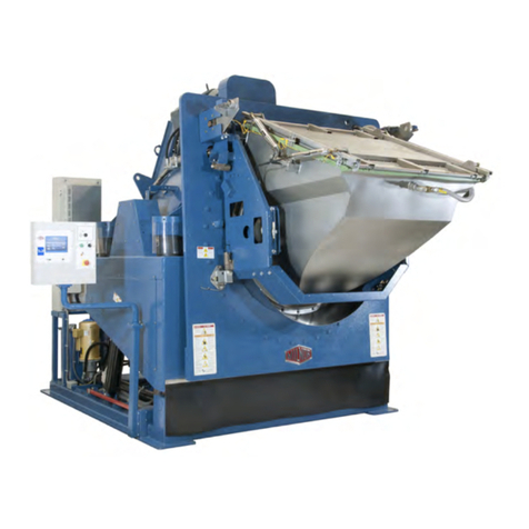
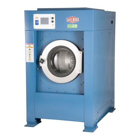
Milnor 30010CGE User manual

Published Manual Number: MTCEXB01
• Specified Date: 20040120
• As-of Date: 20040120
• Access Date: 20040120
• Depth: detail
• Applicability: CEX
• Language Code: ENG01, Purpose: publication, Format: 1colA
General—
Electronic Coin Washer-
extractor Control with
Seven Formulas
PELLERIN MILNOR CORPORATION POST OFFICE BOX 400, KENNER, LOUISIANA 70063 - 0400, U.S.A.

Applicable Milnor®products by model number:
30010CGE 30015C4E 30015CGE 30022C4E 36021C4E

Preface
PELLERIN MILNOR CORPORATION
Preface
BICEUK01 (Published) Book specs- Dates: 20040120 / 20040120 / 20040120 Lang: ENG01 Applic: CEX
i. About This Manual
i. 1. Scope
This manual provides commissioning, operating, and troubleshooting instructions for Milnor®
washer-extractors in the C_E model line, which are equipped with the Milnor®electronic seven
formula coin washer-extractor control. See the installation manual for information on machine
installation procedures and mechanical requirements. See the service manual for preventive
maintenance, service procedures, and mechanical parts identification. See the schematic manual
for electrical parts identification and electrical troubleshooting instructions.
i. 2. How to Identify this Manual and its Included Documents[Document
BIUUUD13]
A complete identification of this manual or any document in this manual must include all
specifications shown on the front cover, as defined below:
Published manual number—Primary identification number for the manual or any variation of it.
Specified date—The approximate date of introduction of the product or product change this
manual covers.
As-of date—When a manual for an old product is generated, any new information about the old
product developed up to this date will be included in the manual.
Access date—The date the manual was generated (assembled and formatted).
Applicability—Code(s) that represent a group of machines this manual applies to and/or actual
model numbers of applicable machines. The complete list of applicable models is provided
inside the front cover. If “not used” appears here, this is not a product manual, but has another
purpose such as to provide administrative procedures.
Language Code—A code representing the specific language and dialect of this manual. “Eng01”
identifies the language/dialect of the manual as United States English, which is that of the
Milnor factory.
When referring to any document used in this manual (as identified by an eight-character
document number such as BIUUUD13 at the start of the document), a complete identification of
the document must include all specifications shown on the front cover, except substituting the
document number for the published manual number.
i. 3. Trademarks of Pellerin Milnor Corporation[Document BIUUUD14]
The following, some of which may be used in this publication, are trademarks of Pellerin Milnor
Corporation:

Preface
PELLERIN MILNOR CORPORATION
Table 1: Trademarks
Ampsaver® E-P Express® Hydro-Cushion® Milnor® Totaltrol®
Autolint® E-P OneTouch® Mentor® Miltrac
Autovac E-P Plus® Mildata® Staph-Guard®
CBW® Gear Guardian® Milnet® System 7®
— End of BICEUK01 —
BICEXS04 (Published) Book specs- Dates: 20040120 / 20040120 / 20040120 Lang: ENG01 Applic: CEX
ii. General Safety Requirements—Vital Information for Coin
Laundry Owners/Managers and Employees
Notice 1 : Important Safety Instructions—Read and save all instructions
The placard shown in Figure 1 instructs laundry owners, their managers and employees about
installing, maintaining, testing, and providing instructions to users for safe operation of the
machine. The instructions on this placard and other general safety requirements are described in
more detail following the figure.
Figure 1: C4E and CGE Warning Placard for Owners, Managers, and Employees
Incorrect installation, neglected preventive maintenance, abuse, and/or improper repairs or
changes to the machine can cause unsafe operation and personal injuries, such as multiple
fractures, amputations, or death. The owner/manager is responsible for understanding and
ensuring the proper operation and maintenance of the machine. The owner/manager must be
familiar with the contents of all machine instruction manuals, and verify that the machine is
operated as described in this manual and all other manuals pertaining to this machine. The
owner/manager should direct any questions about these instructions to a Milnor®dealer or the
Milnor®Customer Service department.

Preface
PELLERIN MILNOR CORPORATION
ii. 1. Laundry Facility
Provide a supporting floor that is strong and rigid enough to support—with a reasonable safety
factor and without undue or objectionable deflection—the weight of the fully loaded machine and
the forces transmitted by it during operation. Provide sufficient clearance for machine movement.
The laundry facility must provide protection from the elements. Do not install the machine
where it will be exposed to the weather.
As of this writing, the National Electrical Code requires a clearly marked electric disconnect
switch within sight of the machine and no farther away from the machine than 50 feet. Local
codes may have additional requirements.
You are urged to consult your licensed electrician and take immediate steps to comply if your
installation does not meet the National Electrical Code requirement and/or local codes.
Under certain conditions, hydrogen gas may be produced in a hot water system that has not been
used for 2 weeks or more. Hydrogen gas is explosive. if the hot water system has not been used
for such a period, before using a washing machine, turn on all hot water faucets and let the water
flow from each for several minutes. This will release any accumulated hydrogen gas. As the gas
is flammable, do not smoke or use an open flame during this time.
ii. 2. Maintenance
Ensure the machine is inspected and serviced in accordance with good practice and the preventive
maintenance schedule. Replace belts, pulleys, bearing seals, etc. before they are severely worn.
Do not permit inspection, service or maintenance by unqualified personnel.
ii. 2.1. The Danger from Operating a Damaged Machine—The door interlock must permit
the door to be opened for a short time after the start of the cycle then prevent it from being
opened for the remainder of the cycle. Test this mechanism daily, as explained in Section iv.
“Daily Test of Door Interlock”.
Immediately investigate any evidence of impending failure and make needed repairs. Conditions
indicating that service is required include, among others, leaking seals, valves, and hoses, motor
or bearings making whining or grinding noises or becoming abnormally hot, and cracks or bends
in the cylinder, shell, or frame.
WARNING 2 : Multiple Hazards—Operating a damaged machine can kill or injure
personnel, further damage or destroy the machine, damage property, and/or void the warranty.
• Do not permit the machine to be operated with any evidence of damage or malfunction.
• Do not disable any safety device or permit the machine to be operated with a
malfunctioning safety device.
WARNING 3 : Explosion Hazards—Cylinder—A damaged cylinder can rip apart during
extraction, puncturing the shell and discharging metal fragments at high speed.
• Do not permit the machine to be operated with any evidence of damage or malfunction.
ii. 2.2. The Danger of Exposing Normally Guarded Hazards—Every guard and access
panel on the machine exists to isolate energized or moving parts from machine users and
bystanders and must be securely in place for safe operation.
WARNING 4 : Electrocution and Electrical Burn Hazards—Contact with high voltage
will electrocute or burn you. High voltage is present at the machine unless the main machine
power disconnect is off.

Preface
PELLERIN MILNOR CORPORATION
• Do not service machine unless qualified and authorized.
• Lock out and tag out power at the main machine disconnect before servicing, or in
accordance with factory service procedures.
• Replace guards and covers before returning the machine to service and do not permit the
machine to be operated with guards or covers removed.
WARNING 5 : Entan
g
le and Crush Hazards—Contact with moving components normally
isolated by guards, covers, and panels, can entangle and crush your limbs. These components
move automatically.
• Do not service machine unless qualified and authorized.
• Lock out and tag out power at the main machine disconnect before servicing, or in
accordance with factory service procedures.
• Replace guards and covers before returning the machine to service and do not permit the
machine to be operated with guards or covers removed.
CAUTION 6 : Burn Hazards—Contact with hot goods or machine components can burn you.
• Do not service machine unless qualified and authorized.
• Lock out and tag out power at the main machine disconnect before servicing, or in
accordance with factory service procedures.
• Replace guards and covers before returning the machine to service and do not permit the
machine to be operated with guards or covers removed.
An attendant key is provided with the machine. This key permits an attendant to bypass the coin
acceptor and start a wash program without coins. The key also provides access to the testing and
maintenance functions described in “Testing and Troubleshooting” in the reference manual.
WARNING 7 : Multiple Hazards—Only knowledgeable service personnel can safely
perform the testing and maintenance functions provided by the attendant key. Unauthorized or
unknowledgeable users can be seriously injured or killed.
• Never leave key in lock.
• Understand the consequences of using the testing and maintenance functions.
ii. 3. Disposal
The discarded machine must not pose an entrapment hazard. Before disposal, remove the
cylinder door.
ii. 4. Customer Awareness
A customer safety placard on the machine alerts the customer to immediate hazards from misuse.
The placard is illustrated and described in Section iii. “The Customer Safety Placard—Vital
Information for Coin Laundry Customers, Owners/Managers and Employees”. Keep the safety
placards clean so that the pictures and words are plainly visible. Replace placards
immediately if lost or damaged. See the “Safety Placard Use and Placement” page in the service
manual to identify the placards and properly locate them on the machine.
Use whatever effective means are available, such as monitoring customer activity and posting
signs prominently in the facility, to ensure a safe environment. Customers must understand:
1. the nature of the potential hazards,
2. how to avoid the hazards, and

Preface
PELLERIN MILNOR CORPORATION
3. what to do in the event of an emergency.
— End of BICEXS04 —
BICEXS05 (Published) Book specs- Dates: 20040120 / 20040120 / 20040120 Lang: ENG01 Applic: CEX
iii. The Customer Safety Placard—Vital Information for Coin
Laundry Customers, Owners/Managers and Employees
Notice 8 : Important Safety Instructions—Read and save all instructions.
The customer safety placard shown in Figure 2 was affixed to your Milnor®machine in a location
that is easily visible to customers. This placard warns customers who are about to use the
machine of hazards that can result from improper use. Safety placards help to ensure a safe work
environment and, as with any other machine part, must be properly maintained. Placards must
be kept clean so that the pictures and words are plainly visible. Placards must be replaced
immediately if lost or damaged. See the “Safety Placard Use and Placement” page in the service
manual to identify the placards and properly locate them on the machine.
Figure 2: Customer Safety Placard
Laundry owners, managers and employees must familiarize themselves with these hazards and
actively prevent any condition in their facility which might make accidents from these hazards
more likely. These hazards are described in more detail below.

Preface
PELLERIN MILNOR CORPORATION
iii. 1. The Danger of Child Entrapment and Scalding
There have been child entrapment incidents with machines from various manufacturers. In
each instance, a small child was placed, climbed, or was helped to climb into a front loaded
coin machine and the door was closed behind him. The door locked, the machine started
running, and in one instance, the child was scalded to death.
WARNING 9 : Entrapment/Scald Hazards—
• Never let a child climb into, operate, or play around this machine. Soon after door is
closed, door may lock and basket may fill with very hot water or spin.
• Do not open door if water is in machine.
Milnor®C4E and CGE coin operated washer-extractors have a door interlock which, to protect
against entrapment, permits opening the door during the first 60 seconds after closing the door
and starting the wash program. As additional protection against entrapment, once the door
locks, it may be unlocked by removing power at the wall-mounted disconnect switch or
circuit breaker, which must be part of the installation. The owner/manager must determine,
based on laundry operation, how to best address such an entrapment emergency. For example, the
owner/manager may wish to post clearly visible signs alerting customers to this, or, if an
attendant is always on duty, to make the attendant responsible for responding to such an
emergency.
iii. 2. The Danger of Amputation Related to a Rotating Cylinder
A tremendous amount of energy exists in the rotating cylinder of any washer-extractor,
even at slow speeds. If someone tries to pull goods from a turning basket, the goods can
wrap around his/her arm, entangling the arm and twisting it off.
WARNING 10 : Amputation Hazard—Turning basket can twist off arms.
• Never reach into or pull clothes from a turning basket.
• Machine pauses between reversals. Do not reach into basket until it remains stopped and
“U” flashes on display.
To protect against child entrapment, the controller used on coin machine models in the Milnor®
C4E and CGE lines permit opening the door during the first 60 seconds after closing the door and
starting a wash program. The door locks after 60 seconds (see Note 1).
Note 1: During the first 60 seconds of the cycle, the door may be opened. If this occurs, the wash program
halts, the drain valve opens immediately, the motor stops driving the basket, and—if the machine still has
electric power—a brake is immediately applied to the basket. If the machine did not lose power, closing the
door will cause the wash program to resume where it was interrupted and the door lock delay time to be
reset so that the door can again be opened for 60 seconds from when the door was subsequently closed.
Once the door locks, it remains locked, until one of the two following conditions occurs:
• When the wash cycle runs to completion without interruption, the door unlocks after the cycle
ends and the safety delay time expires. The safety delay allows time for the machine to coast
to a complete stop before allowing the user to open the door and retrieve the goods inside.
• If power is lost during the wash cycle, the door unlocks to allow the user to open the door and
retrieve the goods (see Note 2).
Note 2: In C4E and CGE models, a wash program interrupted by a power loss cannot be restarted. When
power is restored and the door is closed, the customer can start the wash cycle from the beginning by
inserting more coins, or the attendant can turn the Attendant switch to the horizontal position to allow
starting the machine without coins.
Preface
PELLERIN MILNOR CORPORATION
iii. 3. The Danger from Flammable Materials
WARNING 11 : Fire Hazard—Never place items containing gasoline or other flammable
fluids in machine.
Washer-extractors are not designed to handle flammable materials. This includes goods
containing flammable substances as well as flammable cleaning materials such as solvents. In
either case, highly flammable vapors can be given off, especially when the material is heated.
Any source of spark or flame, such as the machine's motor, can then ignite the vapors, resulting in
fire or explosion. Additionally, washing with water and detergent may not fully remove
flammable materials from the goods, posing a severe risk of fire when those goods are placed in a
dryer.
— End of BICEXS05 —
BICEXS03 (Published) Book specs- Dates: 20040120 / 20040120 / 20040120 Lang: ENG01 Applic: CEX
iv. Daily Test of Door Interlock
The C_E door interlock is designed to lock the door after the machine has been running 60
seconds with the door closed. Test this vital safety mechanism daily to verify that it is functioning
properly.
Notice 12 : Daily test of coin counter not required.—This test, referred to in safety
placards used on some older coin-operated models, is not required on current C_E models.
Current models require only the daily door interlock test.
CAUTION 13 : Scald Hazards—Contact with hot bath liquor can scald you.
• During the following test, hold the door firmly closed as shown in Figure 3 to prevent the
door from springing open if the latch retracts during this test.
Figure 3: Hold Door Shut when Testing the Door Latch Interlock
Verify the door locks as follows:
1. Permit the wash program to progress for 90 seconds, but not much longer.
2. Holding the door closed, attempt to depress the door latch handle.
a. If the latch retracts (if the door unlocks), remove the machine from service until the
problem is identified and corrected.
b. If the latch does not retract (if the door is locked), and assuming no other evidence of
safety problems exists, return the machine to normal operation.
— End of BICEXS03 —

Preface
PELLERIN MILNOR CORPORATION
BIUUUK06 (Published) Book specs- Dates: 20040120 / 20040120 / 20040120 Lang: ENG01 Applic: CEX
v. Contacting Milnor®
Your first contact with any question should be your authorized Milnor dealer, but problems or
special situations encountered in the field may require consultation with the Milnor factory.
Written correspondence can be mailed to this address:
Pellerin Milnor Corporation
Post Office Box 400
Kenner, Louisiana 70063-0400
Telephone: 504-467-9591
www.milnor.com
v. 1. Ordering Replacement Parts
In most cases your authorized Milnor dealer can provide any necessary parts for equipment you
purchased from them. If your dealer is not available or able to help you acquire parts, contact the
Milnor parts group.
Milnor Parts
Telephone: 504-467-2787
Fax: 504-469-9777
E-mail: parts@milnor.com
v. 2. Customer Service and Technical Support
For your technical questions or comments about Milnor equipment, contact your Milnor dealer
first. If your dealer is unable to respond, the Milnor customer service group has many years of
collective experience with our equipment. These men and women will give you the best possible
answer to your question.
Milnor Customer Service
Telephone: 504-464-0163
Fax: 504-469-9777
E-mail: service@milnor.com
www.milnor.com (Customer Service)
v. 3. Warranty Information
Your Milnor dealer can address most warranty claims. However, if you have concerns or
questions beyond the scope of your dealer, please contact our warranty group.
Milnor Warranty Administrator
Telephone: 504-712-7735
Fax: 504-469-9777
E-mail: service@milnor.com (Attention: Warranty)
v. 4. Equipment Manuals
If you have suggestions or questions about any part of this manual or any other documentation
included with your machine, the Milnor technical publications group can assist you.
Milnor Technical Publications
Telephone: 504-712-7636
Fax: 504-469-1849

Preface
PELLERIN MILNOR CORPORATION
E-mail: techpub@milnor.com
— End of BIUUUK06 —

Table of Contents
PELLERIN MILNOR CORPORATION
Table of Contents
Sections Figures, Tables, and Supplements
Preface
i. About This Manual (Document BICEUK01)
i.1. Scope
i.2. How to Identify this Manual and its Included Documents
(Document BIUUUD13)
i.3. Trademarks of Pellerin Milnor Corporation (Document
BIUUUD14) Table 1: Trademarks
ii. General Safety Requirements—Vital Information for Coin
Laundry Owners/Managers and Employees (Document
BICEXS04)
Figure 1: C4E and CGE Warning Placard
for Owners, Managers, and Employees
ii.1. Laundry Facility
ii.2. Maintenance
ii.2.1. The Danger from Operating a Damaged Machine
ii.2.2. The Danger of Exposing Normally Guarded Hazards
ii.3. Disposal
ii.4. Customer Awareness
iii. The Customer Safety Placard—Vital Information for Coin
Laundry Customers, Owners/Managers and Employees
(Document BICEXS05)
Figure 2: Customer Safety Placard
iii.1. The Danger of Child Entrapment and Scalding
iii.2. The Danger of Amputation Related to a Rotating Cylinder
iii.3. The Danger from Flammable Materials
iv. Daily Test of Door Interlock (Document BICEXS03) Figure 3: Hold Door Shut when Testing
the Door Latch Interlock
v. Contacting Milnor®(Document BIUUUK06)
v.1. Ordering Replacement Parts
v.2. Customer Service and Technical Support
v.3. Warranty Information
v.4. Equipment Manuals
Table of Contents
Chapter 1. Commissioning
1.1. Important Owner/User Information (Document BICEUK02)
1.1.1. Ensure Safety of All Personnel
1.1.2. Customize the Machine Controller

Table of Contents
PELLERIN MILNOR CORPORATION
Sections Figures, Tables, and Supplements
1.2. About the Forces Transmitted by Milnor®Washer-
extractors (Document BIWUUI02)
1.2.1. Foundation Considerations
1.2.2. How Strong and Rigid? Figure 4: How Rotating Forces Act on the
Foundation
1.3. Important Instructions for Pumped Chemical Inlets
(Document BIWUUI01)
1.3.1. How Pumped Chemical Systems can Internally Damage
the Washer-extractor
Supplement 1: Preventing Dribbling by
Purging Chemical Lines
1.3.2. Locating Chemical System Components to Reduce the
Risk of Internal Damage
Figure 5: Proper Routing of Chemical
Tubing
1.3.3. Preventing Leaks Which Can Injure Personnel and Cause
External Damage
Figure 6: Rear-mounted Water and Liquid
Supply Injector
Figure 7: Rear-mounted Water Inlet
Assembly (C_E Models)
1.4. Electrical Connections for Liquid Chemical Systems
(Document BICEUI01)
1.4.1. Pump Signal Connections Table 2: Chemical Injection Signals
Figure 8: Pump Signal Connections
1.4.2. Timer Stop Connections
Chapter 2. Configuring
2.1. Setting the Coin Counts (Document BICEXC01) Figure 9: Example Coin Count Settings
Figure 10: Processor Board as Viewed in
Machine
Table 3: DIP Switch Settings for Coin
Counts
Chapter 3. Operating
3.1. Control Panel (Document BICEXO01) Figure 11: C_E Control Panel (Typical)
3.1.1. Control Functions During Normal Operation
3.1.2. Control Functions in Attendant Mode
3.2. Determining Load Size (Document BIWUUO01)
3.3. Using the Machine (Document BICEXO02)
3.3.1. Normal Operation (Coins Required) Supplement 2: The Three-Compartment
Supply Injector (Optional)
3.3.2. Attendant Operation (Attendant Key Required)
3.3.3. Viewing and Clearing the Accumulator
3.3.3.1. Viewing the Accumulator Figure 12: Wash Cycle Accumulator
3.3.3.2. Clearing the Accumulator

Table of Contents
PELLERIN MILNOR CORPORATION
Sections Figures, Tables, and Supplements
3.3.4. Error Recovery Supplement 3: Recycle Sequence to
Reduce Vibration During Extract
3.4. Standard Wash Cycles (Document BICEXP01) Table 4: Wash Cycles for Software
Version WUC4E1A/20001-20006
Table 5: Standard Coast and Delay Times
(in seconds)
Chapter 4. Testing and Troubleshooting
4.1. Error Codes (Document BICEXT01) Figure 13: Error Code Display
4.1.1. How to Clear Error Conditions Figure 14: Normal Position of Attendant
Switch
Figure 15: Attendant Position of Attendant
Switch
Table 6: Quick Reference for Error Codes
4.1.2. Explanations of Error Codes
4.2. Controller Inputs and Outputs (Document BICEXT02)
4.2.1. Resuming Normal Operation
4.2.2. Viewing Inputs Figure 16: Viewing Inputs in Attendant
Mode
Table 7: Input Signals
4.2.3. Actuating Outputs and Functional Tests Table 8: Output Signals
4.2.4. Functional Tests
4.2.4.1. Functional Test 12
4.2.4.2. Functional Test 13

Chapter 1. Commissioning
PELLERIN MILNOR CORPORATION
Chapter 1
Commissioning
BICEUK02 (Published) Book specs- Dates: 20040120 / 20040120 / 20040120 Lang: ENG01 Applic: CEX
1.1. Important Owner/User Information
The following two procedures must be completed before this machine is placed in service:
1. Ensure the safety of all customers and laundry personnel.
2. Customize the machine controller for the desired number of coins per wash cycle.
1.1.1. Ensure Safety of All Personnel
Ensure that all personnel who will maintain this machine or oversee its operation read the safety
documents in this manual before permitting them to access the machine. Ensure that all user
manuals are available to the appropriate personnel and that all precautions explained in all
applicable manuals are observed.
Always require that customers, employed attendants, and qualified maintenance technicians
follow the safety guidelines in all applicable machine manuals. Allow only competent technicians
with the proper training and qualifications to maintain or repair this machine.
1.1.2. Customize the Machine Controller
Customizing the controller in this machine consists of setting the seven banks of DIP switches on
the micro-controller board for the desired coin count for each formula, as described in Section
2.1. “Setting the Coin Counts”. Always verify the coin count settings when the machine is first
placed in service and any time the micro-controller board is replaced.
— End of BICEUK02 —
BIWUUI02 (Published) Book specs- Dates: 20040120 / 20040120 / 20040120 Lang: ENG01 Applic: CEX
1.2. About the Forces Transmitted by Milnor®Washer-extractors
During washing and extracting, all washer-extractors transmit both static and dynamic (cyclic)
forces to the floor, foundation, or any other supporting structure. During washing, the impact of
the goods as they drop imparts forces which are quite difficult to quantify. Size for size, both
rigid and flexibly-mounted machines transmit approximately the same forces during washing.
During extracting, rigid machines transmit forces up to 30 times greater than equivalent flexibly-
mounted models. The actual magnitude of these forces vary according to several factors:
• machine size,
• final extraction speed,
• amount, condition, and type of goods being processed,
• the liquor level and chemical conditions in the bath preceding extraction, and
• other miscellaneous factors.

Chapter 1. Commissioning
PELLERIN MILNOR CORPORATION
Estimates of the maximum force normally encountered are available for each Milnor®model and
size upon request. Floor or foundation sizes shown on any Milnor®document are only for on-
grade situations based only on previous experience without implying any warranty, obligation, or
responsibility on our part.
1.2.1. Foundation Considerations
Size for size, rigid washer-extractors naturally require a stronger, more rigid floor, foundation, or
other supporting structure than flexibly-mounted models. If the supporting soil under the slab is
itself strong and rigid enough and has not subsided to leave the floor slab suspended without
support, on grade installations can often be made directly to an existing floor slab if it has enough
strength and rigidity to safely withstand our published forces without transmitting undue
vibration. If the subsoil has subsided, or if the floor slab itself has insufficient strength and
rigidity, a deeper foundation, poured as to become monolithic with the floor slab, may be
required. Support pilings may even be required if the subsoil itself is “springy” (i.e., if its
resonant frequency is near the operating speed of the machine). Above-grade installations of rigid
machines also require a sufficiently strong and rigid floor or other supporting structure as
described below.
1.2.2. How Strong and Rigid?
Many building codes in the U.S.A. specify that laundry floors must have a minimum live load
capacity of 150 pounds per square foot (732 kilograms per square meter). However, even
compliance with this or any other standard does not necessarily guarantee sufficient rigidity. In
any event, it is the sole responsibility of the owner/user to assure that the floor and/or any other
supporting structure exceeds not only all applicable building codes, but also that the floor and/or
any other supporting structure for each washer-extractor or group of washer-extractors actually
has sufficient strength and rigidity, plus a reasonable factor of safety for both, to support the
weight of all the fully loaded machine(s) including the weight of the water and goods, and
including the published 360-degree rotating sinusoidal RMS forces that are transmitted by the
machine(s). Moreover, the floor, foundation, or other supporting structure must have sufficient
rigidity (i.e., a natural or resonant frequency many times greater than the machine speed with a
reasonable factor of safety); otherwise, the mentioned 360-degree rotating sinusoidal RMS forces
can be multiplied and magnified many times. It is especially important to consider all potential
vibration problems that might occur due to all possible combinations of forcing frequencies
(rotating speeds) of the machine(s) compared to the natural frequencies of the floor and/or any
other supporting structure(s). A qualified soil and/or structural engineer must be engaged for this
purpose.

Chapter 1. Commissioning
PELLERIN MILNOR CORPORATION
Figure 4: How Rotating Forces Act on the Foundation
Typical Rigid Machine
Legend
A. Direction of force
B. Load
C. Rotation (Frequency = RPM / 60)
.
Figure 4 above is intended to depict both on-grade and above-grade installations as well as
models installed directly on a floor slab or on a foundation poured integrally with the slab.
Current machine data is available from Milnor®upon request. All data is subject to change
without notice and may have changed since last printed. It is the sole responsibility of every
potential owner to obtain written confirmation that any data furnished by Milnor®applies for the
model(s) and serial number(s) of the specific machines.
— End of BIWUUI02 —
BIWUUI01 (Published) Book specs- Dates: 20040120 / 20040120 / 20040120 Lang: ENG01 Applic: CEX
1.3. Important Instructions for Pumped Chemical Inlets
Although pumped liquid chemical supply systems are not common in coin laundry installations,
this information applies to Milnor®C_E electronic coin machine models equipped with optional
connection points for such liquid supplies. Machines equipped with this option use the injector
manifold illustrated in Figure 6. Machines equipped with the standard supply chute or three-
compartment supply injector employ the water inlet manifold shown in Figure 7. See the service
manual for an illustration of the three-compartment supply injector.
1.3.1. How Pumped Chemical Systems can Internally Damage the
Washer-extractor
Many pumped liquid chemical systems dribble concentrated chemicals out of the injection tubes
when the system is not used for relatively long periods of time—as after working hours and
during weekends. This puts highly concentrated corrosive chemicals in direct contact with dry
stainless steel surfaces, and often directly on any textiles left in the machine. Chemical
deterioration (rusting) of the stainless steel and damage to the textiles is the inevitable
result.
Pellerin Milnor Corporation accepts absolutely no responsibility whatsoever for damage to its
equipment or to any textiles therein when concentrated chemicals dribble out of the injection
tubes onto any part of the machine or its contents.
Supplement 1 Preventing Dribbling by Purging Chemical Lines
Although the injection site is flushed by washer agitation on some models and after each
injection on other models to aid the injection process, this flushing provides absolutely no

Chapter 1. Commissioning
PELLERIN MILNOR CORPORATION
protection against harmful dribble which occurs later—when the machine is no longer in use.
One foolproof solution for “dribbling” is to completely purge the appropriate chemical injection
tube with fresh water after every injection, so that only fresh water (which cannot cause a
problem) can dribble out.
Obviously, it is the sole responsibility of the pump and/or chemical supplier (not the machine
manufacturer) to furnish such a flushing device. (We understand that such flushing type
chemical injection systems—both for retrofit to existing systems and for new installations—are
now offered by others.)
1.3.2. Locating Chemical System Components to Reduce the Risk of
Internal Damage
If the tubes, pumps, and chemical tanks are kept well below the injection point, the likelihood of
“after-hours dribbling” is reduced, but not totally eliminated.
We therefore urge that tubes from any non-flushing pumped chemical system be connected as
shown in Figure 5. Although fresh-water flushing the just-used tubes after each injection would
be better, we believe routing the tubes as indicated will probably minimize the dribbling effect
about as much as possible without flushing. Never permit tanks, pumps, or any portion of the
tubes to be higher than the injection point. If loops in the injection tubes are employed, make sure
the entire loop is well below the injection point.
Figure 5: Proper Routing of Chemical Tubing
Note 3: As shown in Figure 5, all tanks, pumps, and tubing must be lower than the injection point on the
machine and must not dribble chemicals into the machine, nor leak chemicals externally onto any portion
of the machine or its surroundings.
1.3.3. Preventing Leaks Which Can Injure Personnel and Cause
External Damage
Any ports on the inlet are plugged at the Milnor®factory. When replacing plugs with fittings or
when reinstalling plugs, always use the sealant furnished (LocTite®RTV Silicone Adhesive or
equivalent). Use properly sized hose barbs, always use clamps, and check for leaks. Use the hose
barbs furnished with your machine only if they provide the proper fit for the tubes employed.
Ensure that excessive pressures cannot build up that might burst or disconnect tubing. Instruct the
operator to monitor for leaks and report any occurences.

Chapter 1. Commissioning
PELLERIN MILNOR CORPORATION
When calibrating injections, it is permissible to remove tubes from barbed fittings to take
samples. However, always check for leaks after installing tubes and clamps. A preferable method
for sampling is to install a three-way valve, or two two-way valves and a tee fitting, onto each
injection tube.
WARNING 14 : Avoid chemical burns and corrosion—Concentrated liquid chemicals
leaking from a chemical system can burn skin and eyes, cause other types of injury or illness, and
corrode machine components.
• Ensure that excessive pressures cannot build up which might burst or disconnect a
chemical delivery tube.
• Ensure that there are no external chemical leaks when the system is installed or calibrated.
• Periodically check the system for leaks during operation.
CAUTION 15 : Avoid corrosion and textile damage—Chemicals dribbling into the
machine when it is idle will corrode machine components and damage any textiles left in the
machine.
• If possible, use a system that flushes the entire chemical delivery tube after each injection.
• If a non-flushing system is used, install tanks, pumps, and tubing below the injection point
on the machine, such that chemicals travel to the machine at an upward angle.
CAUTION 16 : Avoid explosions—Certain chemicals will react chemically when
combined. Consult with your chemical supplier representative about the safe use of chemicals.

Chapter 1. Commissioning
PELLERIN MILNOR CORPORATION
Figure 6: Rear-mounted Water and Liquid Supply Injector
Figure Legend
.
1. Assembly for 36- and 42-
inch models
2. Assembly for 30-inch
models
3. Cold water inlet
4. Hot water inlet
5. Water outlet into shell
6. Chemical outlet into drain
sump
7. 3/8-inch NPT chemical
connection (typical)
8. Flushing water inlet (1/2-
inch hose)
9. Water inlet mouth
This manual suits for next models
4
Table of contents
Other Milnor Controllers manuals

Milnor
Milnor E-P Express User manual

Milnor
Milnor MilTouch User manual

Milnor
Milnor MilTouch-EX Manual

Milnor
Milnor Milnor Phase 7.2.2 User manual

Milnor
Milnor MilTouch MWF27Z8 Series Manual

Milnor
Milnor Miltrac Use and care manual

Milnor
Milnor MilTouch Manual

Milnor
Milnor E-P Plus Service manual

Milnor
Milnor MilTouch User manual

Milnor
Milnor MilTouch MWF27Z8 Series Manual