INSTALLATION
Carefully unpack the pump and select a mounting location on the wall, the case of the air conditioner, or
floor. The pump must be level and the inlet must be below the lowest drain, either coil or furnace. If wall or
case mounting, use the mounting tabs on either side of the reservoir to secure the pump.
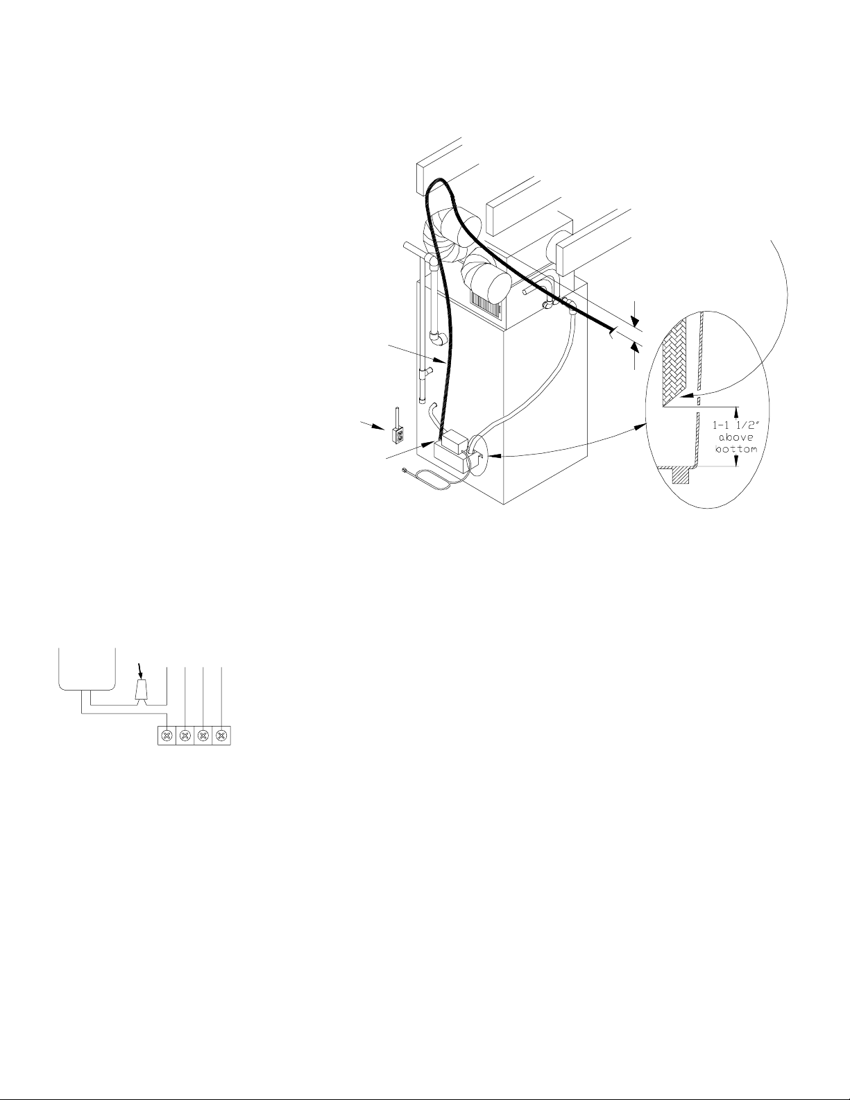
PIPING—Run flexible tubing or pipe
from the evaporator and furnace to
the pump. Insert the pipe into the
drain inlet hole. Make sure the pipe
does not interfere with the float.
Cut an angle on the inlet pipe so
that it doesn’t close off against the
bottom of the pump. See Figure 1 –
exploded detail.
Connect 3/8” ID tubing to the
barbed check valve. Extend this
tubing straight up as high as neces-
sary. (Do not extend this tubing
past the head/GPH of the pump
installed). Do not kink the tubing,
as this will block the flow. From this
high point, slope the discharge tub-
ing downward to a point above the
drain, then turn down and extend
to a point below or level with the
bottom of the condensate pump. If
it is not possible to slope the dis-
charge tubing downwards, make an inverted “U” trap directly above the pump at the highest point. (Figure 1)
ELECTRICAL CONNECTIONS—review precautions on previous page
LINE VOLTAGE—Connect power cord to the proper voltage as indicated on the motor nameplate. Connect
only to a source of constant power, not an intermittent source such as a fan or limit control circuit.
LOW VOLTAGE—AUXILIARY SAFETY SWITCH–Connect the leads of auxiliary
safety switch to the thermostat control circuit of the air conditioner/furnace. This
will disrupt the thermostat demand in a high water condition. (Figure 2)
CAUTION –Thermostat demand disruption should not be utilized if cooling or
heating requirements are a necessity. An alarm system should be used with the
auxiliary switch instead.
OPERATION
After proper installation, the operation of the HARTELL condensate pump is automatic. Water is collected in
the reservoir and pumped out when the float raises to a pre-set point. As the water level goes down the float
turns off the motor at another pre-set point. Under most circumstances the pump requires little maintenance
for efficient operation. If a problem occurs, please refer to the maintenance instructions below.
MAINTENANCE
If a problem develops, the following guidelines can help to return the pump to service.
PUMP DOES NOT RUN
- Check to see that the power to the system (air conditioner and/or furnace) is on to allow production of con-
densate.
- Check that the pump is plugged in and the circuit is active (i.e. fuse or breaker not blown).
- Check the level of water in the reservoir; the level must be within 2” of the reservoir top to activate the
Hose Clamp
3/8" ID Tubing
To Floor Drain
or Laundry Tub.
Ceiling and Joists
Grounded
Outlet
Discharge tube should
slope down toward
outlet if possible
Do not kink tube !
Cut tubing at an angle
so that bottom of
reservoir doesn't close it.
Be sure tubing does not
interfere with float.
Figure 1
Condensate
Pump
Yellow
Yellow
Red
White
Green
Yellow
Wire Nut From Thermostat
Furnace / A.C.
Figure 2


