M E T E R I N G P U M P S
B E A M O P E R A T E D P L U N G E R
LINC 82 ver. 04102003 - pn 15104
LINC MILTON ROY 201 IVYLAND ROAD IVYLAND PA, 18974 USA TEL. 215.441.0800 Page 6
ody (fig. 3, item 1) and "peen"
the all onto the seat to
ensure proper sealing.
6. Install the repaired suction
check valve into the pump
ody. Tighten securely.
7. Reconnect the suction piping.
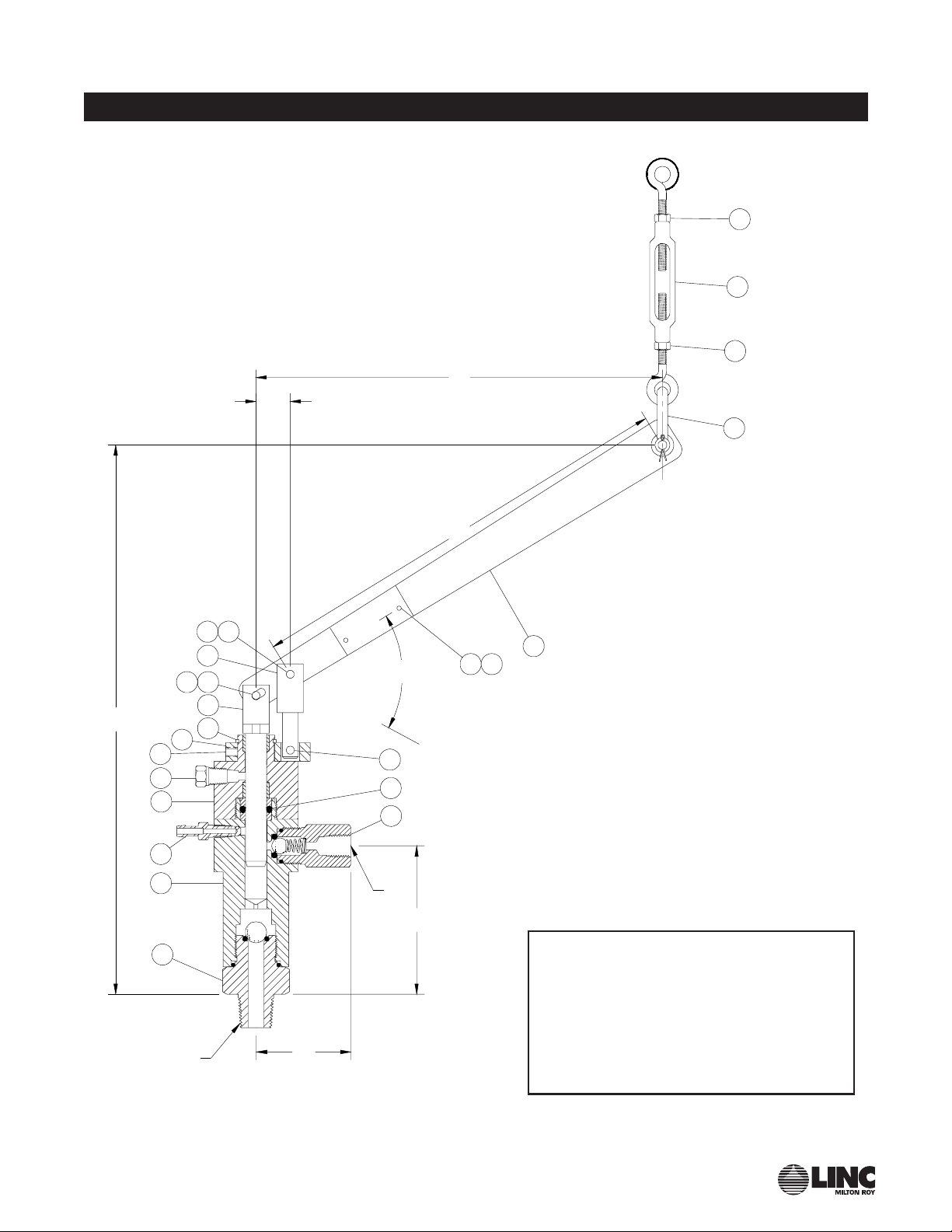
Discharge Check Valve,
Figure 1, item 15 & Figure 2:
1. Assure that the pump is
isolated from the rest of the
system.
2. Disconnect the piping from
the check valve.
3. Unscrew the check valve
ody (fig. 2, item 1) from the
pump lower housing (fig. 1,
item 13).
4. Remove and discard the
o-rings (fig. 2, items 4 & 5).
5. Inspect the all and spring
(fig. 2, items 2 & 3) for dam-
age. Replace if necessary.
Reassem le the check valve
using new o-rings. If the seat
o-ring is Teflon, install in into
the pump lower housing (fig.
1, item 13) and "peen" the
all onto the seat to ensure
proper sealing.
6. Install the repaired discharge
check valve into the pump
lower housing. Place the all
on the o-ring seat followed y
the spring (small end of the
spring toward the all) and
screw the discharge check
valve ody into the pump
lower housing. Tighten
securely.
7. Reconnect the discharge
piping.
Plunger and Plunger Seal,
Figure 1, item 6 & 16:
1. Assure that the pump is
isolated from the rest of the
system.
2. Remove the pin retainer and
pins separating the plunger
assem ly from the eam (fig.
1, items 4 & 5). Remove the
retaining ring and loosen the
set screw and separate the
swivel ring (fig. 1, items 7, 9
& 8) from the packing lock.
3. Grasp the plunger assem ly
(fig. 1, item 6) and pull up out
of the packing lock (fig. 1,
item 11) to remove. Inspect
the plunger for wear, espe-
cially longitudinal grooves.
Replace the plunger assem ly
if necessary.
4. With a pipe or strap wrench
separate the packing lock
(fig. 1, item 11) from the lower
housing (fig. 1, item 13).
5. Remove the plunger seal and
seal ack-ups, where used,
from the lower housing (fig.
1, items 16 & 13). Carefully
remove the seal ack-up and
seal. Inspect for wear or
deterioration from eing
attacked y the chemical the
pump is pumping.
6. Replace the plunger seal and
plunger seal ack-ups if
needed (see parts lists on
page 9). If the plunger seal
is the o-ring type, it should
e installed with a plunger
seal ack-up on each side of
the o-ring. If the plunger seal
is of the Uniseal type, it
should e installed with the
expander ring down toward
the lower housing. Extreme
care should e taken not to
scratch or distort these parts.
7. After the seal has een
replaced, lu ricate with a light
oil to protect against possi le
damage during assem ly.
8. Screw the packing lock onto
the lower housing and tighten
securely. Slide the plunger
assem ly into the packing
lock and down into place.
Install the swivel ring with the
retaining ring and eam with
the pin and pin retainer. See
step 2 a ove under this sec-
tion.
9. If the leed screw has een
removed, install and tighten
securely.
Plunger and Plunger Seal
Lubrication
1. Remove the plug from the
pump ody (fig. 1, item 10).
2. Add silicone ase lu ricant
(Dow Corning DC-7, part
#10354) or equal into the port
where the plug was removed.
Approximately 0.5cc will e
required for each refill.
Replace the plug.
Note Do not use a grease gun
or any metal tool to insert the lu ri-
cant into the pump to prevent dam-
age to the plunger or plunger seal.
3. Silicone lu ricant should e
added every 4 - 6 weeks
depending upon operation
conditions.
M E T E R I N G P U M P S