manuals.online logo
Brands
  1. Home
  2. •
  3. Brands
  4. •
  5. Milton Roy
  6. •
  7. Water Pump
  8. •
  9. Milton Roy GA Series Installation and maintenance instructions

Milton Roy GA Series Installation and maintenance instructions

START UP & COMMISSIONING
MANUAL
G™A - G™M SERIES
PUMP
This manual should be made available to the
person responsible for installation and the
commissioning.
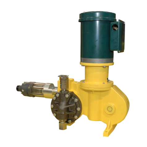
G™A
G™M
Date : 08/2010 N / Ref : Basic_G_US
2
DECLARATION « CE » DE CONFORMITE
F CONFORME A LA REGLEMENTATION CI-DESSOUS
-DIRECTIVE "MACHINES"
DIRECTIVE DU CONSEIL DU 17 mai 2006 (2006/42 CEE) CONCERNANT LE
RAPPROCHEMENT DES LEGISLATIONS DES ETATS MEMBRES RELATIVES AUX
MACHINES.
Nous, MILTON ROY EUROPE 27360 PONT SAINT PIERREFrance déclarons que le
matériel désigné ci-après est en conformité avec la directive "machines" sous réserve que
l'installation, l'utilisation et la maintenance soient effectuées suivant les régles de l'art et selon
les prescriptions définies dans la notice d'instructions.
"EC" DECLARATION OF CONFORMITY
GB CONFORMS WITH THE REGULATIONS BELOW
- "MACHINES" DIRECTIVE
DIRECTIVE OF THE COUNCIL OF may 17, 2006 (2006/42 EEC), CONCERNING THE
APPROXIMATION OF THE LAWS OF MEMBER STATES RELATIVE TO MACHINES.
We, MILTON ROY EUROPE 27360 PONT SAINT PIERRE, France
hereby declare that the equipment designated below : conforms with the "machines" directive,
on the condition that installation, use and maintenance are performed in keeping with
recognized workmanship practices and according to the specifications given in the instruction
manual. EG-KONFORMITÄTSERKLÄRUNG
D IN KONFORMITÄT DER NACHSTEHENDEN BESTIMMUNGEN
- EG-MASCHINENRICHTLINIE
RICHTLINIE DES RATS VOM 17.mai 2006 (2006/42 EWG), BEZÜGLICH DER
ANNÄHERUNG DER GESETZGEBUNGEN DER MITGLIEDSSTAATEN AUF DEM GEBIET
DES MASCHINENWESENS.
Wir, DOSAPRO MILTON ROY 27360 PONT SAINT PIERREFRANCE erklären, daß
die nachstehend bezeichneten Gerätschaften : der EG-Maschinenrichtlinie konform ist, falls
Einbau, Verwendung und Wartung fachgerecht und unter Einhaltung der in der
Gebrauchsanleitung enthaltenen Vorschriften erfolgen.
EG FABRIKANTENCONFORMVERKLARING
NL CONFORM VAN HET HIERONDER VERMELDE REGLEMENT
- RICHTLIJN « MACHINES »
DOOR DE RAAD VAN DE EUROPESE UNIE OP KAN 2006 UITGEVAARDIGD ALS EG-
RICHTLIJN 2006/42, INZAKE DE HARMONISATIE VAN DE WETGEVING DER LIDSTATEN
BETREFFENDE MACHINES.
De ondergetekenden, MILTON ROY EUROPE 27360 PONT SAINT PIERRE
,FRANKRIJK. verklaren dat het hierna vermelde materiaal overeenstemt met de richtlijn
«machines» op voorwaarde dat installatie, gebruik en onderhoud vakkundig en volgens de
betreffende handleidingen plaatsvinden.
DICHIARAZIONE DI CONFORMITA' "CE"
I CONFORME DELLA NORMATIVA SOTTO DESCRITTA
- DIRETTIVA "MACCHINE"
DIRETTIVA DEL CONSIGLIO DEL 17 potere 2006 (2006/42 CEE) IN SEGUITO
ALL'UNIFORMAZIONE DELLE LEGISLAZIONI DEGLI STATI MEMBRI RELATIVE ALLE
MACCHINE.
La società MILTON ROY EUROPE 27360 PONT SAINT PIERREFRANCIA
dichiara che l'apparecchiatura descritta di seguito : è conforme alla eservaa "macchine",
con la eserva che l'installazione, l'utilizzazione e la manutenzione vengano effettuate
attenendosi alle regole d'arte e rispettando le procedure descritte nel manuale d'istruzioni.
3
DECLARACION "CE" DE CONFORMIDAD
E CONFORME AL LA REGLAMENTACION SIGUIENTE
- DIRECTIVAS "MAQUINAS"
DIRECTIVA DEL CONSEJO DEL 17 DE MAYO DE 2006 (2006/42 CEE) RELATIVA AL
ACERCAMIENTO DE LAS LEGISLACIONES DE LOS ESTADOS MIEMBROS EN LO QUE
RESPECTA A LAS MÁQUINAS.
Nosotros,MILTON ROY EUROPE - 27360 PONT SAINT PIERRE – FRANCIA Declaramos
que el matériel que a continuación se designa : cumple la directiva "máquinas" siempre y
cuando la instalación, el uso y el mantenimiento sean efectuados de conformidad con la
normativa profesional y cumpliendo las prescripciones del manual de instrucciones.
DECLARAÇÃO "CE" DE CONFORMIDADE
P CONFORME DA REGULAMENTAÇÃO ABAIXO
- DIRECTIVA "MÁQUINAS"
DIRECTIVA DO CONSELHO DO DIA 17 DE PODER DE 2006 (2006/42 CEE) NO QUE SE
REFERE À APROXIMAÇÃO DAS LEGISLAÇÕES DOS ESTADOS MEMBROS RELATIVAS
ÀS MÁQUINAS.
Nós, MILTON ROY EUROPE - 27360 Pont Saint Pierre – FRANCE , declaramos que o
material designado em seguida : está em conformidade com a directiva "máquinas" sob
reserva que a instalação, utilização e manutenção sejam efectuadas seguindo as regras da
arte e segundo as prescrições da nota de instruções.
EF-OVERENSSTEMMELSESERKLÆRING
DK I OVERENSSTEMMELSE MED I NEDENSTÅENDE BESTEMMELSER
- "MASKIN"DIREKTIV
RÅDETS DIREKTIV AF 17 ma 2006 OM INDBYRDES TILNÆRMELSE AF
MEDLEMSSTATERNES LOVGIVNING OM MASKINER (2006/42/EØF).
Underskrevne: DOSAPRO MILTON ROY - 27360 Pont Saint Pierre - FRANKRIG
erklærer hermed, at nedenstående udstyr : er i overensstemmelse med "maskin"direktivet
under forudsætning af, at montering, anvendelse og vedligeholdelse foregår i henhold til god
faglig praksis og de i vejledningen angivne forskrifter.
"EG"-INTYG OM UPPFYLLANDE
SW I ENLIGHET I NEDANSTÅENDE BESTÄMMELSE
- "MASKIN"ÄDIREKTIV
DIREKTIV FRÅN RÅDET, DEN 17 KAN 2006 (2006/42 EEC) RÖRANDE NÄRMANDE AV
MEDLEMSSTATERNAS LAGSTIFTNINGAR FÖR MASKINER.
Vi, MILTON ROY EUROPE - 27360 Pont Saint Pierre – FRANKRIKE intygar att nedan
beskriven utrustning : överensstämmer med "maskin"-direktivet under förutsättning att den
installareas, används och underhålls enligt konstens regler och enligt de beskrivningar som
ges i användarinstruktionen.
"EU"-TODISTUS VAATIMUSTEN TÄYTTÄMISESTÄ
FIN ALLAOLEVAN MÄÄRÄYKSEN MUKAISESTI
- KONEDIREKTIIVI
NEUVOSTON DIREKTIIVI, 17. Toukokuu 2006 (2006/42 EEC), KOSKIEN
JÄSENVALTIOIDEN KONEISIIN LIITTYVIEN LAINSÄÄDÄNTÖJEN LÄHENTYMISTÄ.
Me, MILTON ROY EUROPE - 27360 Pont Saint Pierre – RANSKA todistamme, että
seuraavassa selostettu varustus : vastaa konedirektiiviä edellyttäen, että se asennetaan, sitä
käytetään ja huolletaan sääntöjen ja käyttöohjeissa olevien selostusten mukaisesti.
∆ΗΛΩΣΗ ΠΙΣΤΟΤΗΤΑΣ "ΕΚ"
GR ΣΥΜΦΩΝΑ ΜΕ ΤΟ"ΜΗΧΑΝΗΜΑΤΑ" ΡΥΘΜΙΣΗΣ
Ο∆ΗΓΙΑ "ΜΗΧΑΝΗΜΑΤΑ" Ο∆ΗΓΙΑ ΤΟΥ ΣΥΜΒΟΥΛΙΟΥ ΤΗΣ 122ης Μπορώ 2006 (2006/42
ΕΟΚ), ΠΟΥ ΑΦΟΡΑ ΤΗΝ ΠΡΟΣ ΕΙΤΙΣΗ ΤΩΝ ΝΟΜΟΘ ΕΣΙΩΝ ΤΩΝ ΚΡΑΤΩΝ
ΜΕΛΩΝ ΣΧΕΤΙΚΑ ΜΕ ΤΑ ΜΗΧΑΝΗΜΑΤΑ.
ΗMILTON ROY EUROPE - 27360 PONT SAINT PIERRE – FRANCE
δηλωνουµε óτι το παρακατω περιγραϕóµενο µηχανηµα :
ειναι συµϕωνο προς την οδηγια "Μηχανηµατα" , µε την επιϕυλαξη óτι η εγκατασταση, η χρη
ση και η συντηρηση του θα πραγµατοποιουνται συµϕωνα προς τους κανονες της τεχνης και τ
ις προδιαγραϕες που οριζονται απó τις οδηγιες χρηοης.
4
RU "ЕС" ДЕКЛАРАЦИЯ ОСООТВЕТСВИИ ПРОДУКЦИИ
ПРОДУКЦИЯ СООТВЕТСВИУЕТ НОРМАМ, ПРИВЕДЕННЫМ НИЖЕ - ДИРЕКТИВЕ О
"МЕХАНИЧЕСКИХ ИЗДЕЛИЯХ"
ДИРЕКТИВА СОВЕТА (КОНСУЛЬСТВА) ОТ 17 МАЯ, 2006 (2006/42 EEC),
ОТНОСЯЩИЕЙСЯ КСОБЛЮДЕНИЮ ЗАКОНОВ УЧАСТНИКОВ ОБЩЕСТВА
МЕХАНИЧЕСКИХ ИЗДЕЛИЙ (МАШИН).
МЫ, КОМПАНИЯ MILTON ROY EUROPE, адрес 27360 PONT SAINT PIERRE, ФРАНЦИЯ
НАСТОЯЩИМ ЗАЯВЛЯЕМ, ЧТО ОБОРУДОВАНИЕ ОПИСАНОЕ НИЖЕ СООТВЕТСВУЕТ
ДИРЕКТИВЕ О«МЕХАНИЧЕСКИХ ИЗДЕЛИЯХ» ПРИ УСЛОВИИ, ЧТО ЕГО УСТАНОВКА,
ИСПОЛЬЗОВАНИЕ ИОБСЛУЖИВАНИЕ ПРОИЗВОДИЛОСЬ КВАЛИФИЦИРОВАННЫМ
ПЕРСОНАЛОМ ИВСООТВЕТСВИЕ СИНСТРУКЦИЕЙ ПО ЭКСПЛУАТАЦИИ.
Alain LAMPERIER
Production Manager
5
CONTENTS
I – PRECAUTIONS 8
II - DESCRIPTION
II - 1. Unpacking and storage 10
II - 2. Description 10
II - 3. Safety and health instructions 11
II - 4. Accessories 11
III - INSTALLATION
III - 1. Technical data 12
III - 2. Hydraulic installation 13
III - 3. Drip collection 13
III - 4. Manipulation 14
III - 5. Handling 14
III - 6. Electrical installation 15
IV – START UP
IV - 1. Procedures before start up 16
IV - 2. Start up 16
IV - 3. Failures on start up 16
For additional information on the pump and its options, please refer to the CD-Rom
delivered with the pump.
6
PART I - PRECAUTIONS
The following precautions should be considered while using the dosing pumps from MILTON
ROY EUROPE range. Please read carefully this section before performing the installation.
Protective clothing
ALWAYS wear protective clothing, mask for the face, protective glasses and gloves
while using or working next to the dosing pump. Some additional precautions should
be taken in conformity with the nature of liquid being pumped. Please refer to the
precaution of the MSDS provided with the liquid.
Water pre-priming
All the pumps are pre-primed with water at the factory. If the liquid to be pumped is not
compatible with water, dismantle the liquid end of the pump. Dry up completely the
liquid end, the check valves and the balls. Reassemble the liquid end by tightening
the screws in a diagonal pattern. Fill the liquid end with the liquid to be pumped
before priming the pump. (It will ease the start-up.)
Chemical compatibility
Check that the material of the liquid end is (chemically ) compatible with the liquid to
be pumped. Always refer to the liquid provider and to Chemical Resistance Chart for
compatibility with your pump. Contact your local distributor for additional information.
Piping connection
The suction and discharge piping connection and the piping size should not be
reduced. The size of the discharge piping should not be increased. Ensure that the
piping is FIRMLY FIXED before use. ALWAYS use piping provided with the pump, it
is specially designed for use with the pump connections. All piping should be
protected and attached to avoid possible damage in case of any breakage or
accidental damages. If the piping is exposed to the sun, a black UV protective piping
should be considered. Check regularly the piping for cracks and replace portions when
required.
Connectors
All connectors shall be tightened by hand. An additional turn of 1/8 to 1/4 of 360°
might be necessary to ensure tightness. Any excessive tightening or using a tool
might damage the connecting device and the seals or the liquid end.
All the GTM series pumps are tightened with o-ring seals. NEVER use Teflon® tape
or a sealing compound to seal the joints. The Teflon® tape can be used on injection
nozzles on the 1/2” NPT side, on the connection of stainless steel liquid end, or
directly on suction or discharge piping.
7
Installation
Always comply with local regulations and requirements. Ensure that the installation is
not obstructed. Comply with local piping regulations. Milton Roy Europe is not
responsible of the pump installation.
Back pressure valve / Anti-syphon valve
If you are pumping downhill or into low or no pressure system, a back
pressure/antisiphon device such as Four-Function Valve should be installed to
prevent over pumping or siphoning. Contact your distributor for further information.
Electrical installation
WARNING: To reduce the risk of electrical shock, the metering pump must be
plugged into a properly grounded grounding-type receptacle with ratings conforming
to the data on the pump nameplate. The pump must be connected to a good ground.
Do not use adapters! All wiring must conform to local electrical codes. If the supply
cord is damaged, it must be replaced by the manufacturer, stocking distributor, or
authorized repair center in order to avoid a hazard.
Line Depressurization
To reduce the risk of chemical splash during disassembly or maintenance, all
installations should be equipped with line depressurization capability. Using Four-
Function Valve (-FV) is one way to include this feature.
Ground Fault Circuit Interrupter
WARNING: To reduce the risk of electric shock, install only on a circuit protected by
a Ground Fault Circuit Interrupter (GFCI).
Clean less
The pump should be clean and dust should be wiped off.
Weight
If the weight of the pump is over 25Kg use adequate means to manipulate/transport it.
8
PART II - DESCRIPTION
II - 1. UNPACKING AND STORAGE
II - 1.1 UNPACKING
The packaging must be carefully examined on receipt in order to ensure that the contents
have not sustained any obvious damage. Precautions must be taken when opening the
packaging in order to avoid damaging accessories which may be secured inside the
packaging. Examine the contents and check them off against the delivery note.
II - 1.2 STORAGE PRECAUTIONS
II - 1.2.1 Storage for less than six months
Equipment shall preferably be stored in its original packaging and protected from
adverse weather conditions.
II - 1.2.2 Storage for more than six months
Store the pump in its original packaging. In addition, packaging in heat-sealing
plastic cover and desiccant bags must be provided for. The quantity of desiccant
bags should be adapted to the storage period and to the packaging volume Store
protected from adverse weather conditions.
II - 2. DESCRIPTION (See figure 1.1a)
The « SERIES GTM » Model A pump is a compact electromechanical metering pump that
is life-lubricated with oil in a sealed housing, with capacity adjustment in operation or when
stopped It is made up of the following components.
It is made up of the following components:
•a drive device comprising a motor,
•a mechanical assembly,
•a liquid end.
The tightness/seal between mechanical part and the liquid end is made by a diaphragm.
The different parts of the pump are described on the below drawing 1.1a
Model GA™ Model GM™
1 Motor 5 Valve assembly (suction) 9Stroke locking device
2 Mechanical assembly 6 Liquid end
3 Stroke adjustment knob 7 Liquid end mounting assembly
4 Valve assembly (discharge) 8 Leak detection port
Figure 1.1a
For the stroke adjustment option, refer to the installation leaflet of the stroke adjustment
option, delivered with the pump
9
II - 3. SAFETY AND HEALTH INSTRUCTIONS
The personnel responsible for installing, operating and maintaining this equipment must
become acquainted with, assimilate and comply with the contents of this manual in order:
•Avoid any possible risk to themselves or to third parties,
•Ensure the reliability of the equipment
•Avoid any error or pollution due to incorrect operation.
Any servicing on this equipment must be carried out when it is stopped. Any accidental
start-up must be prevented (either by locking the switch or removing the fuse on the power
supply line).
A notice must be attached to the location of the switch to warn that servicing is being
carried out on the equipment.
Switch off the power supply as soon as any fault is detected during operation:
•Abnormal heating or unusual noise.
Special care has to be taken for chemicals used in the process (acids, bases, oxiding /
reducing solutions, ...).
II - 4. ACCESSORIES (See Figure 1.2a)
Certain accessories are supplied as standard equipment or as options, as applicable.
•A foot valve (equipped with a filter). This avoids risk of unpriming the pump while
filtering of the fluid.
•An injection nozzle: It isolates the liquid being pumped from the main flow and
creates a back pressure necessary for proper running.
An injection nozzle A foot valve
Figure 1.2a (non contractual drawing)
10
PART III - INSTALLATION
III - 1. TECHNICAL DATA
III - 1.1 COMMON TECHNICAL DATA
•Noise level, in dB A: < 70
•Ambient running temperature: -10°C - +40°C
•Max temperature of pumped liquids: -10°C - +40°C
•Flow and max allowable working pressure are indicated on the pump nameplate.
The running test is made with water and a motor running at 50Hz.
III - 1.2 GM PUMP - TECHNICAL DATA
CODE of pump GM
2
GM
5
GM
10
GM
25
GM
50
GM
90
GM
120
GM
170
GM
240
GM
330
GM
400
GM
500
Steady state
accuracy (flow
rate10between10%
and 100%) ± 3% ±1,5%
Max. suction
pressure, in bar
(Pasp) 5 4 3
Suction head, in
meters water head
(Ha)
4 2.5
III - 1.3 GA PUMP - TECHNICAL DATA
CODE OF PUMP GA2 GA5 GA10 GA25 GA45 GA90 GA120 GA170
Steady state
accuracy (flow
rate10between10%
and 100%)
± 2 %
Max. suction
pressure, in bar
(Pasp)
2
Max. suction
pressure, in bar
(Pasp)
42.5
III – 1.4 LUBRIFICATION
The pump is life-lubricated with oil. However if for some reason oil needs to be replaced, refer
to the specific manual included in the CD-Rom delivered with the pump.
11
III - 2. HYDRAULIC INSTALLATION
For information on hydraulic installation of a dosing pump, refer to the "Advice sheets" of the
CD ROM provided with the pump. The main points are briefly described below.
III - 2.1 GENERAL (See figure 2.1b)
There must be no swan-necks or stagnant volumes which are liable to trap air or gast
Stresses due to incorrect alignment of piping with respect to the centreline of valves must
be avoided as far as possible.
•Remove burrs and clean the piping before fitting.
•It is advisable to provide for a calibrating chamber in order to calibrate the pump in
service conditions.
III - 2.2 PIPING ON THE SUCTION CIRCUIT (See figure 2.1b)
•If your pump is flooded, a shutt-off valve will be required (F 2.1d).
•If your pump is not flooded (suction lift), install the foot valve equipped with the filter
upstream of the above-mentioned item(F 2.1c)
•For viscous products: consult us.
•Install the pump as near as possible to the suction tank.
III - 2.3 PIPING ON THE DISCHARGE CIRCUIT (See figure 2.1d)
•Provide for a safety valve on the discharge pipe, designed to protect the installation.
•It is advisable to install a priming valve on the maintenance of the pump easier.
III - 2.4 CONNECTION DEVICES (See figure 2.1a)
Use connection device adapted to your piping size.
Figure 2.1a
III - 3. DRIP COLLECTION (See figure 1.1a.)
Provide for outlets so that any leak or drips can be easily drained off without any danger. This
is especially important in the case of harmful liquids.
Position a tray under the plain hole located at the bottom of the liquid end mounting assembly
to collect leaks in the event of rupture of the diaphragm or boot.
12
III - 4. HANDLING
The « SERIES G » Model A and M pump requires no special precautions owing to its light
weight. Proceed with mounting as soon as it is set up on site.
III - 5. COMMISSIONING
Fix the pump to a horizontal support. Keep in mind to leaving sufficient space around the
pump to allow maintenance and setting.
Pumps installed outside should be protected by a shelter (adapted to the climatic conditions
of the location)
Pump in suction
(Figure 2.1c)
Pump in discharge
(Figure 2.1d)
1 Tank 7 4-function valve 11 Pulsation
dampener
2 Foot valve (equipped with a filter) 8 Injection nozzle
4 Metering pump 9 Shutt-off valve
6 Process 10 Filter
Figure 2.1b
13
III - 6. ELECTRICAL INSTALLATION
III - 6.1 MOTOR CONNECTIONS
The characteristics of the electrical power supply do not match the specifications of the
motor connections. Connect the motor as per electrical scheme indicated on the terminal
box
Replace the existing cables by those of the electrical supply.
CAUTION: Do not forget to connect the earth terminal on the motor to the
equipment earth conductor.
The electrical protection installed for the motor (fuse or thermal protection) must be suitable for
the motor's rated current
14
PART IV - START UP
IV - 1.PROCEDURES BEFORE START UP
Special care has to be taken for chemicals used in the process
(acids, bases, oxiding/reducing solutions...).
•Check that the pump is secured to its support (Chapter III - 5. COMMISSIONING).
•Check the pipe fitting torque.
•Check the opening of all the isolating valves installed on the suction and discharge
circuits. If your pump is equipped with a 4-function valve, see the relevant specific
documentation. If the discharge circuit is equipped with an injection nozzle or a
back-pressure valve, open the priming valve on the discharge side (if there is no
priming valve, disconnect the piping on the discharge side). This allows you to
check for the presence of liquid if the pump is installed in flooded suction or to prime
the pump if it is installed in suction lift.
•Set the pump capacity adjustment to 0% (stroke adjustment knob)
•Check the compatibility of the liquid end material with the liquid to be pumped.
IV - 1.1 CHECKING THE ELECTRICAL CONNECTION OF THE MOTOR
Start up the pump to check the motor's direction of rotation. It must comply with that
indicated by the arrow marked on the pump cover.
IV - 2 START UP
•Once all the checks and procedures described in the previous section have been
carried out, start up the pump.
•Check visually and by listening. (In particular, check that there are no suspicious
noises).
•Make sure that the stroke adjustment knob is unlocked.
•Adjust the pump capacity gradually from 0% to 100% and control either.
- The liquid output at priming valve
- or, the noise of the liquid when it discharges from the outlet check valve (if your
installation is not equipped with a Priming Valve).
Priming has been achieved when one of these two processes is carried out.
If a Priming Valve is installed close it, otherwise connect the outlet discharge line.
•Set the pump to the desired capacity. Lock the stroke adjustment knob with the
stroke locking device.
IV- 3. FAILURES ON START UP
IV - 3.1 PROBLEMS WITH MOTOR
The motor runs with difficulty and heats up.
•The characteristics of the electrical power supply do not match the specifications of
the motor.
TRI
Phase
One phase is incorrectly connected.
The electrical connection used is not suitable.
•Check that the pressure on the discharge side is compatible with the equipment’s
capabilities.
•Too many flow pulsations: a pulsation dampener is required, or the pulsation
dampener installed is of the wrong size, or the pressurization of the pulsation
dampener (2/3 of the working pressure).
TRI
Phase
The direction of rotation of the motor is incorrect. (Check using the arrow marked on
the cover). Reverse the direction Procedures.(See Chapter IV - 1.1. Checking the
electrical connection of the motor).
15
IV - 3.2 PROBLEMS WITH FLOW RATE
The flow rate is lower than desired
•The pump capacity is incorrectly adjusted: adjust the capacity to the desired value
and lock the stroke adjustment knob.
•The suction power is insufficient (Piping cross-section too small or piping too long):
replace the pipes with ones with a larger cross-section or install the pump in flooded
suction.
•The leak-tightness of the suction pipes is unsatisfactory.
•The viscosity of the liquid is incompatible with the capabilities offered by your pump
version.
•The filter is blocked, clean it.
The capacity is greater than desired
•The pump capacity is incorrectly adjusted: adjust the capacity to the desired value
and lock the stroke adjustment knob.
•A siphoning phenomenon is observed: check that the discharge pressure is higher
by at least 1,5 bar than the suction pressure. Install a back pressure valve on the
discharge portion
•Too many flow pulsations: a pulsation dampener is required, or the pulsation
dampener installed is of the wrong size, or the pressurization of the pulsation
dampener is incorrect.
The capacity is variable
•This problem may be due to particles from the piping which interfere with the
operation of the valve assemblies: clean the piping and the valve assemblies.
•Lack of back pressure on the discharge portion: install a back pressure valve on the
discharge portion
IV - 3.3 OPERATION - SCHEDULE FOR CHECKS AND MAINTENANCE
OPERATIONS
The programme of checks and maintenance operations depends on the conditions in which
the equipment is used. For the frequency of maintenance, refer to the instruction manual for
installation, operating and maintenance included in the CD-Rom delivered with the pump. You
can adapt the frequency to the conditions of your exploitation.
16
GUARANTEE
The vendor guarantees his products according to the Milton Roy Europe. General Conditions
of Sale.
The guarantee for components and sub-assemblies not fabricated by the vendor is limited to
that given by the supplier.
The vendor’s guarantee only covers the replacement or the repair, at his cost and in his
factory, of all parts acknowledged by his technical services as being defective due to an error
in conception, of material or of execution.
It is the purchaser's responsibility to prove the said defects. The guarantee does not cover the
replacement of wear parts mentioned in part V - Preventive Maintenance.
The vendor reserves the right to modify all or part of his products in order to satisfy the
guarantee. The guarantee does not cover charges arising from dismantling, assembly,
transport and movements.
The replacement of one or several parts, for whatever reason, does not prolong the period of
guarantee.
The guarantee is not applicable notably in the following cases:
•Installation not in accordance with standard current practice.
•Deterioration or accident resulting from negligence.
•Lack of surveillance or maintenance.
•Modifications to conditions of use.
•Chemical corrosive or erosive attack. The proposed materials of construction are
recommendations subject in all cases to verification and acceptance by the client.
The recommendations, based on the experience of the vendor and the best available
information, do not guarantee against wear or chemical action.
The guarantee ceases:
•If the storage of the material, out with the vendors factory, does not conform to his
recommendations or to current standard practices.
•In case of work or dismantling of the material by someone who does not respect
written recommendations of the instruction manual (when replacing wear parts).
•If parts from another origin are substituted for the original parts supplied by the
manufacturer. The purchaser cannot call on guarantee claims to justify differing
payments.
INDUSTRIAL OWNERSHIP
This manual can only be used by the purchaser or the user. It cannot be distributed,
published, reproduced (partially or totally) or generally communicated to third parties without
the advance, formal written authorisation of the vendor.
Any breach of these rules may result in legal action being taken.
17
18
FRANCE
ASSISTANCE TECHNIQUE : Tél.: 33.(0.2.32.68.30.02 Fax : 33.(0)2.32.68.30.96
PIECES DE RECHANGE : Tél.: 33 (0)2.32.68.30.01 Fax : 33.(0)2.32.68.30.92
ACCUEIL : Tél.: 33.(0)2.32.68.30.00 Fax : 33.(0)2.32.68.30.93
10 Grande Rue 27360 Pont-Saint-Pierre, France
www.dosapro.com email: contact@dosapro.com
UNITED STATED
L.M.I. (LIQUID METRONICS, INC.)
Tél.: 978 263-9800 – Fax : 978 264-9172
8 Post Office Square Acton, MA 01720
www.lmipumps.com
FLOW CONTROL DIVISION :
TECHNICAL ASSISTANCE AND SPARE PARTS :
Tél.: 215.441.0800 – Fax : 215.293.0468
201 Ivyland Road, IVYLAND, PA, 18974
www.miltonroy.com email: customercervice@miltonroy.com
OTHER COUNTRIES :
Representatives in all countries, contact in FRANCE:
INTERNATIONAL SALE DEPARTMENT
Tél.: 33.2.32.68.3004 – Fax : 33.2.32.68.3094
www.dosapro.com email: [email protected]

This manual suits for next models

21

Other Milton Roy Water Pump manuals

Milton Roy MILROYAL D User manual

Milton Roy

Milton Roy MILROYAL D User manual

Milton Roy PRIMEROYAL User manual

Milton Roy

Milton Roy PRIMEROYAL User manual

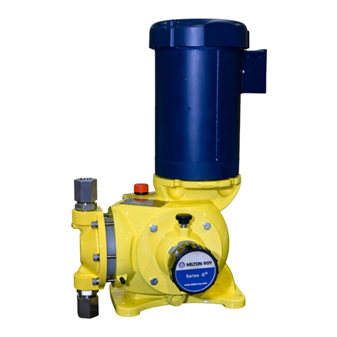
Milton Roy GM Series User manual

Milton Roy

Milton Roy GM Series User manual

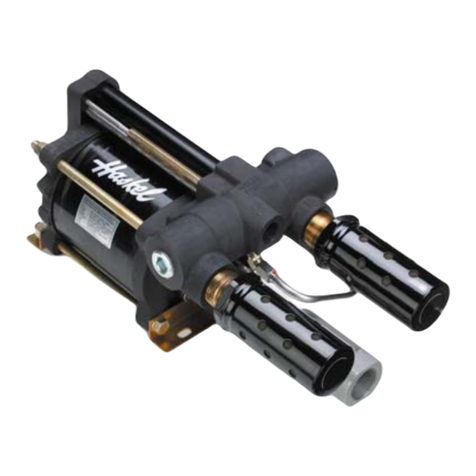
Milton Roy Haskel G Series User manual

Milton Roy

Milton Roy Haskel G Series User manual

Milton Roy MILROYAL B User manual

Milton Roy

Milton Roy MILROYAL B User manual

Milton Roy PRIMEROYAL User manual

Milton Roy

Milton Roy PRIMEROYAL User manual

Milton Roy MILROYAL G User manual

Milton Roy

Milton Roy MILROYAL G User manual

Milton Roy Hartell KT3 Owner's manual

Milton Roy

Milton Roy Hartell KT3 Owner's manual

Milton Roy MAXROY B User manual

Milton Roy

Milton Roy MAXROY B User manual

Milton Roy mROY User manual

Milton Roy

Milton Roy mROY User manual

Milton Roy GB Series User manual

Milton Roy

Milton Roy GB Series User manual

Milton Roy Roytronic A Series User manual

Milton Roy

Milton Roy Roytronic A Series User manual

Milton Roy LINC 82 Series User manual

Milton Roy

Milton Roy LINC 82 Series User manual

Milton Roy G Series Installation guide

Milton Roy

Milton Roy G Series Installation guide

Milton Roy MILROYAL D User manual

Milton Roy

Milton Roy MILROYAL D User manual

Milton Roy MAXROY Series Use and maintenance manual

Milton Roy

Milton Roy MAXROY Series Use and maintenance manual

Milton Roy mRoy XT User manual

Milton Roy

Milton Roy mRoy XT User manual

Milton Roy LMI P1 Installation guide

Milton Roy

Milton Roy LMI P1 Installation guide

Milton Roy MILROYAL D User manual

Milton Roy

Milton Roy MILROYAL D User manual

Milton Roy G Series User manual

Milton Roy

Milton Roy G Series User manual

Milton Roy mRoy B User manual

Milton Roy

Milton Roy mRoy B User manual

Milton Roy mRoy A User manual

Milton Roy

Milton Roy mRoy A User manual

Milton Roy Hartell Pumps Powerflow Series Owner's manual

Milton Roy

Milton Roy Hartell Pumps Powerflow Series Owner's manual

Milton Roy MILROYAL B User manual

Milton Roy

Milton Roy MILROYAL B User manual

Popular Water Pump manuals by other brands

Grundfos Unilift KP 150 manual

Grundfos

Grundfos Unilift KP 150 manual

Zoeller 81 Series installation instructions

Zoeller

Zoeller 81 Series installation instructions

RIKEN P-4 Operation and service manual

RIKEN

RIKEN P-4 Operation and service manual

fluimac TMB Series Operation manual

fluimac

fluimac TMB Series Operation manual

GORMAN-RUPP PUMPS 2D-X.75 1P Installation, operation and maintenance manual

GORMAN-RUPP PUMPS

GORMAN-RUPP PUMPS 2D-X.75 1P Installation, operation and maintenance manual

DAB Hydrodriver A Instruction for installation and maintenance

DAB

DAB Hydrodriver A Instruction for installation and maintenance

Graco SaniForce Series Instructions and parts

Graco

Graco SaniForce Series Instructions and parts

TEXEL MTA-1516 instruction manual

TEXEL

TEXEL MTA-1516 instruction manual

NPC Betta FLO BMLS-M Installation, operation & maintenance instructions

NPC

NPC Betta FLO BMLS-M Installation, operation & maintenance instructions

Simplex G1 manual

Simplex

Simplex G1 manual

Homa Sensoflat C 270 WF Original instruction manual

Homa

Homa Sensoflat C 270 WF Original instruction manual

Edwards Microvac 149-HS instruction manual

Edwards

Edwards Microvac 149-HS instruction manual

Salvatore Robuschi RDV manual

Salvatore Robuschi

Salvatore Robuschi RDV manual

Gardena PTU 3000/4 Operator's manual

Gardena

Gardena PTU 3000/4 Operator's manual

Cole Parmer Mastercraft B/T RAPID-LOAD 77111-30 operating manual

Cole Parmer

Cole Parmer Mastercraft B/T RAPID-LOAD 77111-30 operating manual

Edwards iH80 instruction manual

Edwards

Edwards iH80 instruction manual

Xylem Flygt 2125 Installation, operation and maintenance manual

Xylem

Xylem Flygt 2125 Installation, operation and maintenance manual

Pentair SIATA AQUA CUBIC PLUS Use and maintenance manual

Pentair

Pentair SIATA AQUA CUBIC PLUS Use and maintenance manual

manuals.online logo
manuals.online logoBrands
  • About & Mission
  • Contact us
  • Privacy Policy
  • Terms and Conditions

Copyright 2025 Manuals.Online. All Rights Reserved.