Mindra HK-D07-230-NE1 User manual

MINDRA GREEN ENERGY LLP
TYPE 2 AC EV CHARGER
USERS MANUAL
Edition:V1.1.0

Type 2 AC EV charger Instructions- V1.1.0
About the manual
The manual is prepared for users of Floor-type DC Charging Piles.
Please read the manual carefully before installation, operation, maintenance or inspection
of the product.
Technical service
If any problems found during the use of the charging pile, kindly please contact our
technical service department as below:
For more information, please visit our website: http:// www.mindrasolar.com/
In order to protect and respect intellectual property rights, no companies or individuals
shall provide information in this manual to the third party without any authorization.
To ensure the accuracy, the manual has been carefully reviewed. If any errors found while
using, any comments will be welcomed.
If any conflicts found between the manual and new products, please refer to the extra
specification attached.
Mindra Green energy LLP reserves the right to improve product technologies and
interpret this manual. Product technologies and the manual are subject to changes without
prior notice and relevant technical agreements shall prevail.
Mindra Green energy LLP All rights reserved.
Mindra Green energy LLP
Address: Prasham 102, Devraj Industrial Park
Piplaj - Pirana Rd, Calico Mills, Ahmedabad, Gujarat 382405
TEL: -9157502603
Email:-support@mindrasolar.com
Type 2 AC EV charger Instructions- V1.1.0
Safety Instructions
Please pay special attention to all safety information in the manual. Personal injuries or
causalities might be caused if precautions mentioned in the manual not be observed. Any
personal injury or equipment damages due to customer’s failure in following this manual
shall not be responsible by the Company.
Warning ---- --- means potential dangers. If not avoid, personal
injuries may be caused.
Safety Precautions
⚫Please observe the instructions when using the charger.
⚫Do not carry out wiring when power on.
⚫In case of abnormal situations, please stop using and contact the manufacturer.
⚫Please contact the manufacturer timely in case of abnormal situations during the
operation. Maintenance carried out by other personnel except for professional
technicians may cause further damage, injuries or accidents.
⚫Do not open the charger when the equipment is live or with residual voltage.
⚫Reliable earthing shall be well ensured, otherwise, degrading of insulation
performance may cause leakage or electric shock.
⚫The charger installation and maintenance could only be operated by qualified
electric engineers.
⚫Maintenance and inspection must not be carried out until discharge is confirmed
complete after the main circuit is disconnected.
⚫Do not use the charger that has been found damaged or has faulty parts.
⚫The vehicle connector must not be placed randomly. The plug shall be inserted back
to the protective socket after completion of charging.

Type 2 AC EV charger Instructions- V1.1.0
Rapid Installation Guidance
Installation and Commission Flowchart
Tasks
Check if the installation base and the
installation hole of the charging pile match
Input cable wiring
Charging trial run and commissioning
Fault alarm and treatment
methods (Page 24)
Man-machine interactive
operation (Page 18)
Dimension and Installation
(Page 9)
References
Familiar with the charging process Operation instructions (Page 16)
Inspection and installation
Take the charging pile out of the packing box,
check the product nameplate and confirm
models
Check if the environmental conditions, input/
output cables and other accessories are
complete
Confirm whether the appearance of the
charger pile is damaged
Receiving and
Acceptance
Installation of
the charger pile
Operation and
commissioning
Fault alarm and treatment methods
Introduction (Page 1)
Power distribution (Page 14)

Type 2 AC EV charger Instructions- V1.1.0
Contents
1. INTRODUCTION ........................................................................................................1
1.1 PRODUCT INTRODUCTION.............................................................................1
1.2 PRODUCT MODEL .........................................................................................1
2. PRODUCT MODEL SPECIFICATION....................................................................2
3. NORMATIVE REFERENCE AND SPECIFICATION............................................2
4. ENVIRONMENTAL CONDITIONS .........................................................................3
5. ELECTRIC CHARACTERISTICS............................................................................3
5.1 INPUT CHARACTERISTICS..............................................................................3
5.2 OUTPUT CHARACTERISTICS ..........................................................................4
5.3 PROTECTION CHARACTERISTICS ...................................................................4
5.4 EMC CHARACTERISTICS ..............................................................................5
5.5 SAFETY FEATURES........................................................................................5
5.6 OTHER CHARACTERISTICS ............................................................................6
5.7INDICATOR LIGHT .........................................................................................7
7. DIMENSION AND INSTALLATION........................................................................9
7.1 DIMENSIONS .................................................................................................9
7.2 INSTALLATION METHOD ...........................................................................11
8. POWER DISTRIBUTION.........................................................................................14
8.1 INPUTAC POWER DISTRIBUTION WIRING ..................................................14
8.2 OUTPUTAC VEHICLE CONNECTOR PLUG PIN DEFINITION .........................15
9. OPERATION INSTRUCTION.................................................................................16
9.1 CHECKS BEFORE CHARGING .......................................................................16
9.1.1 Safe checking before charging ............................................................16
9.1.2 Attentions in Operation Process..........................................................16
9.2 CHARGING OPERATION FLOW CHART.........................................................17

Type 2 AC EV charger Instructions- V1.1.0
9.3 CHARGING OPERATION DESCRIPTION.........................................................18
9.3.1 Start Mode Instruction ........................................................................18
9.3.2 Charging Interface Instruction............................................................19
8. System Remote Upgrading Instruction.....................................................23
10. FAULT ALARM AND TREATMENT...................................................................24
10.1 FAULTAND RECOVERY ...........................................................................24
10.2 FAULTALARM AND TREATMENT.............................................................24
11. PACKAGE, TRANSPORTATION AND STORAGE...........................................25
12. MAINTENANCE AND REPAIR............................................................................26
Type 2 AC EV charger Instructions- V1.1.0
1
1. Introduction
1.1 Product Introduction
European standard type 2 wall-mounted AC charger is a new type of AC
charging product developed by Wuhan Hiconics Intelligent Electric Co.,
LTD. This design takes expressing the sense of future as the starting point,
the advanced technical modeling elements and exquisite material ensure
the product a strong sense of The Times.
The design of this charger focuses on product safety performance. With all
plastic molding appearance, insulation protection has greatly strengthened.
With waterproof, dustproof and corrosion proof function and have
environmental protection design with protection grade of IP 54. The
product, with modular design concept, has integrate the vehicle connector,
human-machine interface (HMI), charger, communication and billing parts
together into one cabinet so that it can easily achieve convenient
installation and debugging, simple operation and maintenance, etc.
Products could be applied on large-scale parking lots, residential areas,
shopping malls, hospitals, transfer stations, airports, docks, parks and
scenic spots, etc.
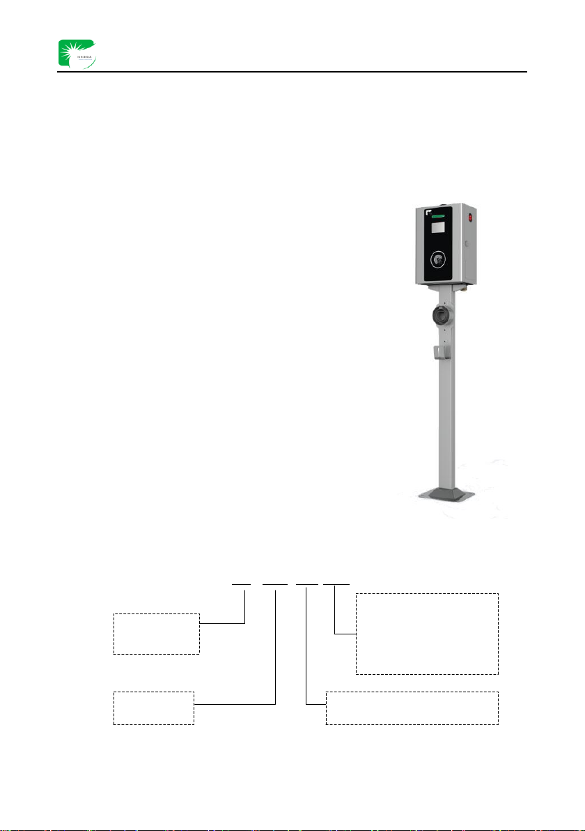
1.2 Product Model
HK:
Manufacturer
Code
HK -D22 -400-NE1
N:Socket type
B:Plug type
E:European Standard
1:Single connector
Single phase AC input: 230VAC
Three phase AC input: 400VAC
Rated Power
/kW
Product model

Type 2 AC EV charger Instructions- V1.1.0
2
2. Product Model Specification
Model
Output
power
Input
Voltage
Rated Output
Current
Input Mode
HK-D07-230-NE1(Socket)
7kW
230V±20%
32A
Single Phase
L+N+PE
HK-D07-230-BE1(Plug)
7kW
230V±20%
32A
HK-D22-400-NE1 (Three phase
22KW socket)
22kW
400V±20%
32A
Three phase
3P+N+PE
HK-D22-400-BE1 (Three phase
22KW plug)
22kW
400V±20%
32A
3. Normative Reference and Specification
IEC 61851-1-2017
Electric vehicle conductive charging system - Part 1: General requirements
IEC 61851-23-2014
Electric vehicle conductive charging system - Part 23: DC electric vehicle
charging station
IEC 61851-24-2014
Electric vehicle conductive charging system - Part 24: Digital communication
between a DC EV charging station and an electric vehicle for control of DC
charging
IEC 61851-21-2-2018
Electric vehicle conductive charging system-Part 1-2: Requirements for
conductive connection of AC/DC power supplies for electric vehicles-Onboard
charging system EMC requirements
IEC 62196-1-2011
Plugs, socket-outlets, vehicle connectors and vehicle inlets –Conductive
charging of electric vehicles –Part 1: General requirements
IEC 62196-3-2014
Plugs, socket-outlets, vehicle connectors and vehicle inlets –Conductive
charging of electric vehicles –Part 3
IEC 60364-4-41:2005
Low-voltage electrical equipment - Part 4-41: Safety protection: protection
against electric shocks
IEC 60990:1999
Measurement of contact current and protective conductor current\
IEC 61439-1:2011
Low-voltage switchgear and control gear assemblies - Part 1: General rules

Type 2 AC EV charger Instructions- V1.1.0
3
IEC 60664-1:2007
Equipment and control equipment components in low-voltage systems - Part 1:
General rules
DIN SPEC70121:2014
Electric vehicle-DC charging system and electric vehicle control system
combined charging system charging digital communication
DIN SPEC70122:2018
Digital communication of the charging system combined by EV DC charging
system and EV control system
4. Environmental Conditions
No.
Item
Technical targets
Unit
Remark
Working
Transportation
Storage
1
Temperature
-30℃~55℃
-40℃~70℃
-40℃~70℃
℃
2
Humidity
5~95
/
5~95
%
Condensation
free
3
Altitude
≤2500
/
≤2500
m
4
Cooling method
Natural Cooling
-
5. Electric Characteristics
5.1 Input characteristics
No.
Item
Technical requirements
Unit
Remark
1
Rated input voltage
7kW
230
VAC
L+N+PE
22kW
400
3P+N+PE
2
Rated input current
7kW
32
A
L+N+PE
22kW
32
3P+N+PE
3
AC input voltage range
7kW
184~276
VAC
Systematical input
voltage
22kW
320~480
VAC
4
AC input frequency range
45~65
Hz
Rated frequency
50Hz/60Hz

Type 2 AC EV charger Instructions- V1.1.0
4
5.2 Output characteristics
No.
Item
Technical requirements
Unit
Remark
1
Rated output power
7
kW
22
2
Rated output voltage
7kW
230
VAC
L+N+PE
22kW
400
3P+N+PE
3
Rated output current
7kW
32
A
L+N+PE
22kW
32
3P+N+PE
4
AC output voltage range
7kW
184~276
VAC
L+N+PE
22kW
320~480
3P+N+PE
5
AC output frequency range
45~65
Hz
Rated frequency
50Hz/60Hz
6
AC output mode
7kW
Single phase three wire
-
L+N+PE
22kW
Three phase five wire
3P+N+PE
5.3 Protection characteristics
No.
Item
Technical requirements
Unit
Remark
1
Input under voltage
protection point
7kW
184
VAC
Adjustable
22kW
320
2
Input overvoltage protection
point
7kW
276
VAC
Adjustable
22kW
480
3
Output over current
protection
yes
-
Exceed 120% of rated
output current
4
Short-circuit protection
yes
-
5
Emergency stop protection
yes
-

Type 2 AC EV charger Instructions- V1.1.0
5
5.4 EMC Characteristics
No.
Item
Technical Requirements
Unit
Remark
1
Electrostatic discharge immunity
Level 3
-
2
Radiofrequency electromagnetic radiation immunity
Level 3
-
3
Power frequency magnetic field immunity test
Level 5
-
4
Electrical fast transient pulse group disturbance
immunity
Level 4
-
5
Surge (impact) immunity
Level 4
-
6
Test for conduction disturbance immunity of RF
field induction
Level 3
-
7
Voltage sag, short interruption immunity
Level 3
-
8
Harmonic current emission limit test
Grade A
-
9
Voltage fluctuation and scintillation test
Grade A
-
10
Power terminal conduction disturbance test
Grade A
-
11
Signal port conduct disturbance check
Grade A
-
12
Protects keyless entry system from radiation
harassment inspection
Grade A
-
13
Shell port radiation harassment inspection
Grade A
-
5.5 Safety features
No.
Item
Technical requirements
Unit
Remark
1
Insulation
resistance
Input-Earth
≥10
MΩ
500VDC
Output-Earth
≥10
MΩ
500VDC
2
Dielectric
strength
Input-Earth
≤10
mA
2.8kVDC
Output-Earth
≤10
mA
2.8kVDC
3
Impulse
withstand
voltage
Input-Earth
No breakdown and insulation damage
-
lightning
impulse±6KV
Output-Earth

Type 2 AC EV charger Instructions- V1.1.0
6
4
Grounding impedance
The maximum resistance between the
charging machine and the site ≤100
mΩ
5
Electric clearance
≥8
mm
6
Creepage distance
≥10
mm
7
Touch current
≤3.5
mA
8
RCD breaker
With
9
Residual current action time
≤0.1
S
10
AC input lightning
protection
Maximum continuous operating voltage is
385 VAC;
Nominal discharge current is 20kA
(5common mode and difference module,
each with 5 times 8/20us impulse wave);
Maximum discharge current is 40kA
Voltage protection level is under 1.8kV
-
5.6 Other characteristics
No.
Item
Technical
requirements
Unit
Remark
1
AC output charging connector
IEC 62196-1-2011
IEC 62196-3-2014
-
2
Standby power consumption
≤15
W
3
Current display accuracy
≤±1
%
4
Voltage display accuracy
≤±0.5
%
5
Meter accuracy level
1
degree
6
IP protection degree
IP54
-
7
Charging cable Length
5
m
Optional
8
Tri-proof protection
moisture proof
mould proof salt
-spray proof
-
The printed circuit board in the
system, connector and other
circuits are dealt

Type 2 AC EV charger Instructions- V1.1.0
7
with moisture proof, mould
proof and salt-spray proof
treatment to ensure that the charger
can run normally in the
environment of damp and salt fog.
9
Anti-corrosion Protection
Anti oxidation
-
Double layer anti-corrosion
measures are taken for the iron
shell, iron supports and parts
exposed outside. The non-iron
metal shell has anti oxidation
protection film or anti oxidation
treatment.
10
Environmental Protection
Meet requirements
of 2011/65/EU; no
cadmium, hydride
and fluoride
-
5.7 Indicator light
No.
Indicator light
Standby
Plugged
In charging
Fault
1
Yellow
ON
/
/
/
2
Green
/
ON
Blinking
/
3
Red
/
/
/
Blinking
Note: When the EV charger is in fault, the red indicator light will blink. Different blinking times stands for
different fault types. Please refer to item 10.2 for detailed explanation.
When the EV charger in remote upgrading process, yellow indicator light will blinking in circle. Please refer
to item 9.3 for detailed explanation.

Type 2 AC EV charger Instructions- V1.1.0
8
6. Product Characteristics
No.
Item
Technical
requirements
Remark
1
Wireless communication
module
2G/4G
Support Unicom , Mobile and Telecom
network
2
Wired LAN
Support
Optional
3
Charging card management
system
Support
Complete card making and issuing
system, with asynchronous settlement
function. Optional
4
Back office monitoring
Support
Optional
5
Remote upgrading function
Support
Optional
6
HMI operation
Support
Equipped with high brightness and High
Definition LCD screen. Optional
7
Alarm and protection
function
Support
8
Plug and charge
Support
Optional
9
Communication protocol
OCPP 1.6J

Type 2 AC EV charger Instructions- V1.1.0
9
7. Dimension and Installation
7.1 Dimensions
(1)The outlook of the EV charger is as follows:
Figure 7.1.1 Outlook of the EV charger
Note: The above figure shows the appearance of standard models. Some customized models have differences
in appearance. The actual charger shall prevail.
Type 2 AC EV charger Instructions- V1.1.0
10
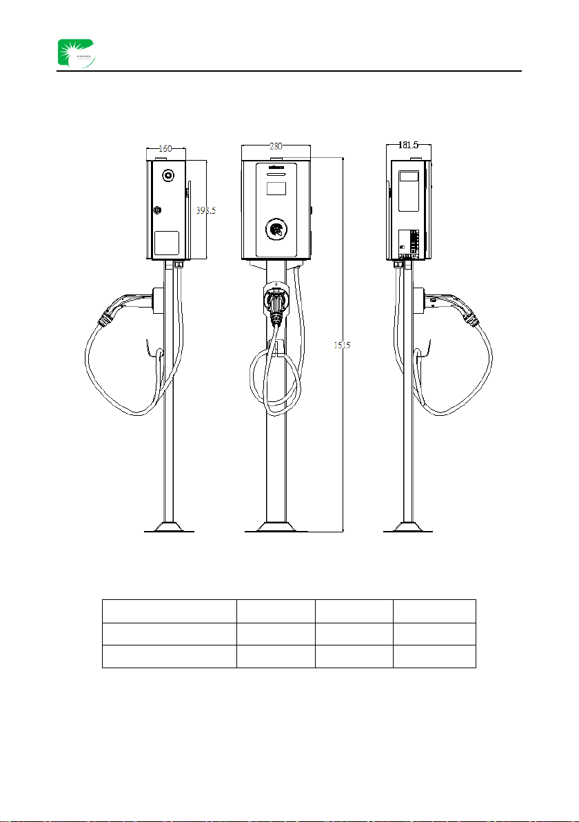
(2)Dimension and size of the EV charger is shown as figure 7.1.2 and chart 7.1.1
Figure 7.1.2 Dimension of the EV charger
Chart 7.1.1 Dimension parameters(Unit:mm)
Length(L)
Width(W)
Height(H)
EV charger
160
280
398.5
EV charger +Charge post
181.5
280
1515

Type 2 AC EV charger Instructions- V1.1.0
11
7.2 Installation Method
(1)If the EV charger is directly installed on the wall, the mounting dimensions of wall pendent are shown in
Figure 7.2.1 and Table 7.2.1:
Figure 7.2.1Backup supporter installation drawings
Chart 7.2.1Backup supporter installation holes parameter(Unit:mm)
L1
L2
L3
Installation Hole (mm)
60
130
266
M6
Installation Method:
➢The EV charger shall be installed and fixed on the vertical surface. In order to ensure a safe and stable
operation of the charger, the vertical surface installed should be smooth and reliable.
➢The power line enters from the bottom of the charger side. For safe and beautiful use of the charger, the
power line-inletting hole shall be reserved on the vertical surface for installation and fixation. Besides,
the power line-inletting hole should be located at an appropriate position on the side of the charger. The
wire line is not allowed to be exposed outside, if any, the exposed wire shall be piped up.
➢The installation height of the charger should be designed in accordance with ergonomics. We
recommend install the charger between 1.3m and 1.5m from the ground to facilitate user operation and
4-M6*80
expansion screw
3-M6*80
expansion screw
Earhook
Backup
supporter

Type 2 AC EV charger Instructions- V1.1.0
12
reduce user fatigue.
➢Before the installation, the charger shall be fixed on the special installation plate of with screws. Then
fix the installation panel on the wall with expansion bolts conforming to specifications. Specific screw
and expansion bolt size should be selected according to charger installation size and site requirements.
➢When the charger installed, charger after sale service and maintenance shall be fully considered.
Note: This installation method is for reference only. The corresponding installation method shall be selected
according to the actual situation on site. Please refer to the detailed construction instructions.
(2)For the wall-mounted AC charger with supporter, the installation size and foundation construction are
shown in Figure 7.2.2, 7.2.3 and chart 7.2.2 below:
Figure 7.2.2 charging post installation drawing
Figure 7.2.3 Construction Drawing
Power line
inletting hole
Concrete base
200MM higher
4-M12*150 Expansion Screw
Right
Left
Front
Back

Type 2 AC EV charger Instructions- V1.1.0
13
L1
L2
Installation Hole (mm)
150
200
Expansion Screw M12
Installation Method:
➢Refer to the above method of installing wall pendant to install the charger on the charging post. The
charging post shall be fixed on the ground.
➢The excavation size of floor support foundation pit shall not be less than 500*550*300mm (length *
width * height).
➢The main body of the foundation is cast in Concrete C25. Top dimensions 300*350*200mm (l * w * h).
➢Referring to the size of the floor bracket base in figure 7.2.2 above, 4 pieces of M12 expansion bolts
need to be embedded in the matrix in advance to ensure that the bolts exposed to 15-20mm of the
matrix for easy installation.
➢Φ 40 PVC pipes need to be embedded in advance on the substrate, as shown in the picture above 7.2.3.
Note: This installation method is for reference only. The corresponding installation method needs to be
selected according to the actual situation on site. Please refer to the detailed construction instructions.
(3)During installation, the recommended specifications of cables used in the user's distribution cabinet are
shown in Table 7.2.3 below.
Chart 7.2.3 Recommended Cable Specification
Model
Input Voltage
Max. Input Current
Cable Specification Recommended
7kW
230V±20%
32A
YJV22-2*16mm²+1*10mm²
22kW
400V±20%
32A
YJV22-3*16mm²+2*10mm²
Note: In order to ensure the safety of electricity on different sites, the cable specifications are recommended to
be large. Users can use the cable according to the site conditions.
Chart 7.2.2 Charging Post Base Installation Holes Parameter(Unit:mm)

Type 2 AC EV charger Instructions- V1.1.0
14
8. Power Distribution
8.1 Input AC Power Distribution Wiring
1、22kW Three phase five wire mode input AC power supply: users need to remove the baffle cover of the
junction box on the side of the charger and connect the cables of recommended specifications in chart 7.2.3 (A,
B, C, N, PE) in turn according to the connection mark of the charger inlet, as shown in Figure 8.1 below.
Figure 8.1 The input AC wiring line drawing of the charger
2、7kW single phase three wire input AC power supply: users need to remove the baffle cover of the junction
box on the side of the charger and connect the cables of recommended specifications in chart 7.2.3 (L, N, PE)
in turn according to the connection mark of the charger inlet, as shown in Figure 8.2 below.
Figure 8.2 The input AC wiring line drawing of the charger
Note: The power of 220V power supply for single-phase household is limited. The user needs to consider
whether the input power can meet the requirements of the vehicle and the charger. Please remember to
read the attached instructions for detailed installation methods. We will not take any responsibility for
any loss caused by improper operation.
Power line inletting hole
Power line inletting hole
This manual suits for next models
2
Table of contents
Popular Automobile Accessories manuals by other brands


ULTIMATE SPEED
ULTIMATE SPEED 279746 Assembly and Safety Advice

SSV Works
SSV Works DF-F65 manual

ULTIMATE SPEED
ULTIMATE SPEED CARBON Assembly and Safety Advice

Witter
Witter F174 Fitting instructions

WeatherTech
WeatherTech No-Drill installation instructions

TAUBENREUTHER
TAUBENREUTHER 1-336050 Installation instruction