manuals.online logo
Brands
  1. Home
  2. •
  3. Brands
  4. •
  5. aci
  6. •
  7. Transducer
  8. •
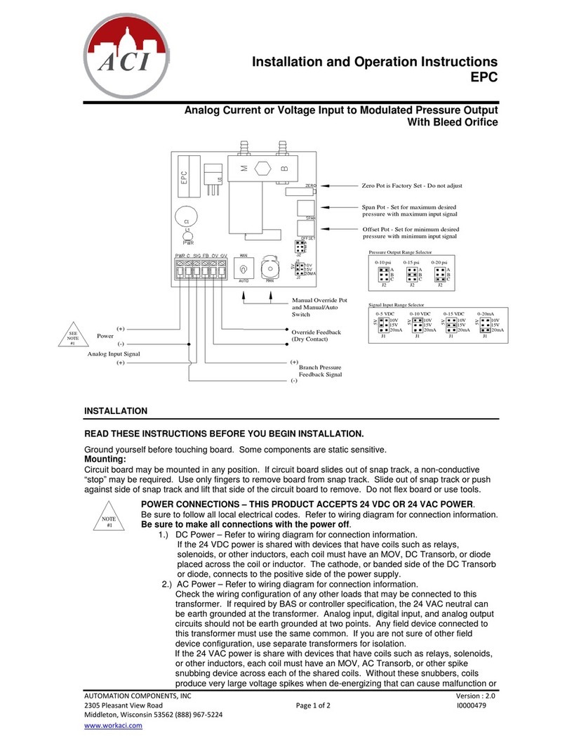
  9. aci ACCESS series Installation instructions

aci ACCESS series Installation instructions

Automation Components, Inc.
2305 Pleasant View Road | Middleton, WI 53562
Phone: 1-888-967-5224 | Website: workaci.com
Page 1
Version: 3.0
I0000590
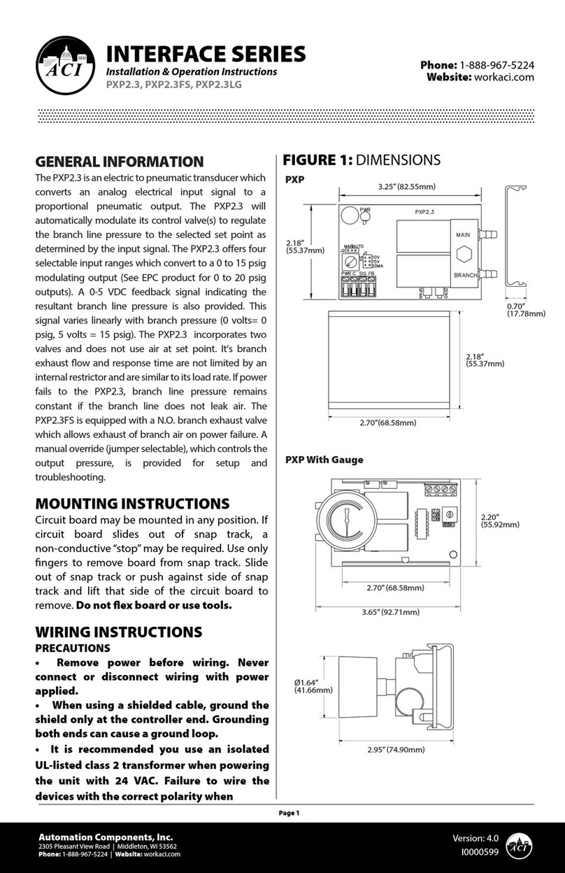
FIGURE 1: DIMENSIONS
INTERFACE SERIES
Installation & Operation Instructions
ATP-R
Phone: 1-888-967-5224
Website: workaci.com
GENERAL INFORMATION
The ATP-R converts an analog signal into a digital
pulse output signal. The user can select eight
standard analog input ranges to the ATP by
changing jumper shunt positions. To select the
output pulse range, the ATP has an eight position
DIP switch. The output pulse is continuous with a
one second o time between pulses.
MOUNTING INSTRUCTIONS
The interface device can be mounted in any
position. If circuit board slides out of snap track, a
non-conductive “stop” may be required. Use only
ngers to remove board from snap track. Slide out
of snap track or push up against side of snap track
and lift that side of the circuit board to remove. Do
not flex board or use tools.
WIRING INSTRUCTIONS
PRECAUTIONS
• Remove power before wiring. Never connect
or disconnect wiring with power applied.
• When using a shielded cable, ground the
shield only at the controller end. Grounding
both ends can cause a ground loop.
• It is recommended you use an isolated
UL-listed class 2 transformer when powering
the unit with 24 VAC. Failure to wire the
devices with the correct polarity when sharing
transformers may result in damage to any
device powered by the shared transformer.
• If the 24 VDC or 24VAC power is shared with
devices that have coils such as relays,
solenoids, or other inductors, each coil must
have an MOV, DC/AC Transorb, Transient
Voltage Suppressor (ACI Part: 142583), or diode placed across the coil or inductor. The cathode,
or banded side of the DC Transorb or diode, connects to the positive side of the power supply.
Without these snubbers, coils produce very large voltage spikes when de-energizing that can
cause malfunction or destruction of electronic circuits.
• All wiring must comply with all local and National Electric Codes.
2.70” (68.58mm)
2.17”
(55.24mm)
2.18” (55.37mm)
2.70”
(68.58mm)
0.70” (17.78mm)
FIGURE 2: WIRING
TABLE 1: JUMPER SHUNTS
Automation Components, Inc.
2305 Pleasant View Road | Middleton, WI 53562
Phone: 1-888-967-5224 | Website: workaci.com
Page 2
Version: 3.0
I0000590
Pwr P2 LO
0V/0mA
10V
15V
P3 HI
20mA
5V
Com Sig CNC NO
ATP
L1
Run
K1
1 2 3 4 5 6 7 8
O
n
Normally Open
Normally Closed
Common
(+)
(-)
Analog Signal Input
24 Volts
AC or DC
(+)
(-)
ATP Pulse Timing
The ATP converts an analog signal into a
digital pulse output signal. The range of the
analog input signal is selectable by the
positions of the jumper shunts P2 and P3 (see
Table 1).
Pulse timing consists of an “ON” pulse and an
“OFF” interval. “OFF” interval is 1 second on
standard and custom ranges.
The standard ranges for Version 1 or 2 are
selected by dip switch 1 “ON” and proper
settings of switches 2 and 3, allows for four
dierent output timing ranges. Switches 4
through 8 are not active when switch 1 is on.
Version 2 operates the same as Version 1
except when the input falls at or below 10%
of the input signal range, no pulse output
occurs, allowing for “OFF” setting of electric
heat Solid State Relays (SSR’s).
P3 (Maximum)
P2 (Offset)
Analog Input
0 - 5V
0 - 10V
0 - 15V
0 - 20mA
1 - 5V
2 - 10V
3 - 15V
4 - 20mA
TABLE 2: ATP PULSE TIMING
TABLE 3: ATP PULSE TIMING (CUSTOM)
Automation Components, Inc.
2305 Pleasant View Road | Middleton, WI 53562
Phone: 1-888-967-5224 | Website: workaci.com
Page 3
Version: 3.0
I0000590
Input Signal Standard Output Range
0-5V 1-5V 0-10V 2-10V 0-15V 3-15V 0-20mA 4-20mA Steps
Dip:1,3
20ms/Step
ON
Dip:1
23ms/Step
ON
Dip:1,2
100ms/Step
ON
Dip:1,2,3
9ms/Step
ON
0 1 0 2 0 3 0 4 0 0 0 0.1 0.59
1.25 2 2.5 4 3.75 6 5 8 64 1.3 1.5 6.5 1.18
2.5 3 5 6 7.5 9 10 12 128 2.5 3 12.8 1.76
3.75 4 7.5 8 11.25 12 15 16 191 3.8 4.5 19.2 2.35
5 5 10 10 15 15 20 20 255 5 6 25.5 2.93
No pulse is output when Version 2 input falls at or below 10% of the
input signal range.
A/D
converter
Johnson Solidyne Andover Novar
The custom mode (refer to Table 3) allows for 128 pulse timing ranges. The custom mode, selected by dip
switch 1 “OFF”, allows switches 2 through 8 to select “ON” pulse timing ranges. These “ON” times are
cumulative and multiple switches can be selected.
Example: 0-10V signal input to an output pulse range of 150 milliseconds (ms) to 38.4 seconds.
1. To obtain a starting pulse signal of 150ms, turn switches 2 & 3 ON, all others OFF (dipswitch 2 on =
50ms at 0 volts, and dipswitch 3 on = 100ms at 0 volts).
2. By looking at the bottom chart note that at 10 volts input signal, the values for switches 2 &3“ON”are
12.8 and 25.6 seconds respectively, totaling 38.4 seconds.
The output range selected is now 150ms to 38.4 seconds.
All times on the charts are shown in seconds (or portion of) with a maximum 6.4 seconds. A pulsing“RUN”
LED on the ATP indicates a pulse width signal output.
Input Signal
0-5V 1-5V 0-10V 2-10V 0-15V 3-15V 0-20mA 4-20mA Steps
0 1 0 2 0 3 0 4 0
1.25 2 2.5 4 3.75 6 5 8 64
2.5 3 5 6 7.5 9 10 12 128
3.75 4 7.5 8 11.25 12 15 16 191
5 5 10 10 15 15 20 20 255
Custom Output Range (DIP Switch Values if ON)
Dip:2
50ms/Step
ON
Dip:3
100ms/Step
ON
Dip:4
200ms/Step
ON
Dip:5
400ms/Step
ON
Dip:6
800ms/Step
ON
Dip:7
1.6s/Step
ON
Dip:8
3.2s/Step
ON
Dip:2-8
6.35s/Step
ON
0.05 0.1 0.2 0.4 0.8 1.6 3.2 6.4
3.3 6.5 13 26 52 104 208 413
6.5 12.9 25.8 52 103 206 413 819
9.6 19.2 38.4 77 154 307 614 1219
12.8 25.6 51.2 102 205 410 819 1626
PRODUCT SPECIFICATIONS
24 VAC or 24VDC, (+/- 10%), 50/60 Hz
50 mA maximum
0-5 VDC, 0-10 VDC, 0-15 VDC, 1-5 VDC, 2-10 VDC, 3-15 VDC @ 1,000,000
0-20 mA, 4-20 mA @ 250
Solidyne™(0.023-6s) | Andover™(0.1-25.5s) | Johnson™(0.02-5s) | Novar™(0.59-2.93s)
Allows for 128 pulse timing ranges
Form “C” Relay
2A @ 24 VAC or 24 VDC
100,000 operations @ 1A, 24 VDC
10,000,000 operations
3A @ 24 VAC only (22-28V)
90° Pluggable Screw Terminal Blocks
16 (1.31 mm) to 26 AWG (0.129 mm)
0.5 Nm (Minimum); 0.6 Nm (Maximum)
35 to 120°F (1.7 to 48.9°C)
10 to 95% non-condensing
-20 to 150°F (-28.9 to 65.5°C)
NON-SPECIFIC INFORMATION
Supply Voltage:
Supply Current:
Input Voltage Signal Range (@
Impedance):
Input Current Signal Range (@
Impedance):
Output Pulse Timing Ranges (Standard
Mode):
Output Pulse Timing Ranges (Custom
Mode):
Output Digital Type, Relay Version
(ATP-R, ATP-Y):
Relay Contact Rating:
Relay Electrical Life:
Relay Mechanical Life:
Output Digital Type, Triac Version
(ATP-Y):
Connections:
Wire Size:
Terminal Block Torque Rating:
Operating Temperature Range:
Operating Humidity Range:
Storage Temperature:
WARRANTY
The ACI ATP Series is covered by ACI’s Two (2) Year Limited Warranty, which is located in the front of ACI’S SENSORS
& TRANSMITTERS CATALOG or can be found on ACI’s website: www.workaci.com.
W.E.E.E. DIRECTIVE
At the end of their useful life the packaging and product should be disposed of via a suitable recycling
centre. Do not dispose of with household waste. Do not burn.
Automation Components, Inc.
2305 Pleasant View Road | Middleton, WI 53562
Phone: 1-888-967-5224 | Website: workaci.com
Page 4
Version: 3.0
I0000590

Other manuals for ACCESS series

16

This manual suits for next models

1

Other aci Transducer manuals

aci ACCESS series Installation instructions

aci

aci ACCESS series Installation instructions

aci WPR2 Series User manual

aci

aci WPR2 Series User manual

aci ACCESS series Installation instructions

aci

aci ACCESS series Installation instructions

aci P51 Series Installation instructions

aci

aci P51 Series Installation instructions

aci EPC User manual

aci

aci EPC User manual

aci ACCESS series Installation instructions

aci

aci ACCESS series Installation instructions

Popular Transducer manuals by other brands

Gems Sensors & Controls 4000K Series Operating & installation instructions

Gems Sensors & Controls

Gems Sensors & Controls 4000K Series Operating & installation instructions

Simrad 38-9 -  REV B datasheet

Simrad

Simrad 38-9 - REV B datasheet

Bitronics M651 user manual

Bitronics

Bitronics M651 user manual

WIKA F9204 operating instructions

WIKA

WIKA F9204 operating instructions

Veris PX3ULX05 Connection instructions

Veris

Veris PX3ULX05 Connection instructions

Veris T-VER-H970-200 Connection instructions

Veris

Veris T-VER-H970-200 Connection instructions

Danfoss VLT series Service manual

Danfoss

Danfoss VLT series Service manual

S+S Regeltechnik RTM-CO2-2S Operating Instructions, Mounting & Installation

S+S Regeltechnik

S+S Regeltechnik RTM-CO2-2S Operating Instructions, Mounting & Installation

AKG DB-1 User instructions

AKG

AKG DB-1 User instructions

LEM ITZ 2000-S FLEX ULTRASTAB manual

LEM

LEM ITZ 2000-S FLEX ULTRASTAB manual

FuehlerSysteme FS1200 operating manual

FuehlerSysteme

FuehlerSysteme FS1200 operating manual

Heise DXD Series Installation and operating instructions

Heise

Heise DXD Series Installation and operating instructions

Induction Dynamics Solid Drive SD1g Installation & use guide

Induction Dynamics

Induction Dynamics Solid Drive SD1g Installation & use guide

Airmar Tilted Element B60 Owner's guide and installation instructions

Airmar

Airmar Tilted Element B60 Owner's guide and installation instructions

Caen ELS CT-BOX quick start guide

Caen ELS

Caen ELS CT-BOX quick start guide

red lion CTL12S manual

red lion

red lion CTL12S manual

red lion CTD manual

red lion

red lion CTD manual

turck IM33-14Ex-CDRi quick start guide

turck

turck IM33-14Ex-CDRi quick start guide

manuals.online logo
manuals.online logoBrands
  • About & Mission
  • Contact us
  • Privacy Policy
  • Terms and Conditions

Copyright 2025 Manuals.Online. All Rights Reserved.