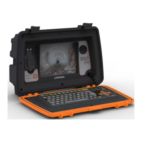
Mini?Cam PROTEUS User guide

Original
Instruction Manual
Version L


This instruction manual is applicable to the PROTEUS
™
inspection system.
A standard system and available options are covered by this document.
Depending on your system conguration you may lack some of the fea-
tures mentioned in this
document.
Disclaimer
Hardware and software mentioned in this document are subject to
continuous development and improvement. Consequently, there may be
minor dierence between the information in the document and the
performance or design of the product. Specications, dimensions and
other statements in this document are subject to change without prior
notice.
Minicam and its suppliers shall not be liable for any damages related to
this software or hardware, or for any other damages whatsoever caused
by the use of or inability to use any Minicam product. This is applicable
even if Minicam has been advised of the damage risk. Under any circum-
stances, Minicam’s entire liability shall be limited to replace such defective
software or hardware that was originally purchased from Minicam.
Minicam Limited
Raven Locks, Ravenscraig Road, Bolton, United Kingdom, M38 9PU
Tel: +44 (0)1942 270524 Email: info@minicam.co.uk
www.minicamgroup.com
Company Registered in England & Wales • Company Registration No: 3728693


CONTENTS
WARRANTY 15
Limited Warranty................................................................................... 15
Extent of the Limited Warranty ........................................................... 15
Conditions of the Limited Warranty ................................................... 15
Warranty Limitations ............................................................................ 15
TEXT CONVENTIONS 16
Danger, Caution and Note .................................................................... 16
Bold Font................................................................................................. 16
Lists.......................................................................................................... 16
Menu Selections .................................................................................... 16
PRODUCT DESCRIPTION 17
EC DECLARATION OF CONFORMITY 18
CE Declaration ....................................................................................... 18
SYSTEM OVERVIEW 19
WARNINGS, SAFETY MEASURES AND CARE 20
Before rst use.......................................................................................22
Safety Measures ....................................................................................24
Maintenance........................................................................................... 26
Cleaning ......................................................................................... 27
General cleaning work ................................................................. 27
Removal and Fitting of the Cable Reel Dirt Tray ...............................28
Checking Plug and Socket Connections ....................................29
CONNECTING THE PROTEUS™ INSPECTION SYSTEM 30
Fitting and removal of crawler wheels ...............................................30
Connection of Cabling between Control Unit and Cable Reel ........ 31
Connection of Cabling between Cable Reel and Crawler ................32

Disconnecting Cabling between Cable Reel and Crawler ...............33
Connection of Camera to Crawler.......................................................34
Connection of Auxiliary Module to Crawler....................................... 35
Pressurising the PROTEUS
™
inspection system.................................36
Check list for adjusting internal pressure of modules............36
Instructions for Pressurising the CRP300 Crawler ...........................37
Instructions for Pressurising the CPL150S Crawler ..........................38
Instructions for Pressurising the CRP140 Crawler............................39
Instructions for Pressurising the CRP90 Crawler..............................40
Instructions for Pressurising the CAM026/26L ................................. 41
Testing the system................................................................................. 42
Lowering the Crawler into the Manhole.............................................43
CCU208 - CONTROL UNIT 44
CCU Overview.........................................................................................45
ON/OFF button .............................................................................46
ALL STOP button...........................................................................46
Power ON sequence..................................................................... 47
Power OFF sequence.................................................................... 47
Crawler function keys ..................................................................48
Survey function keys.................................................................... 49
Media function keys .....................................................................50
Camera function keys .................................................................. 51
Snapshot key ................................................................................. 52
Recording and Playback keys...................................................... 52
QWERTY keys ................................................................................52
Pressurising Operation Mode..............................................................53
Connections and Descriptions.............................................................54
Front view ......................................................................................54
Rear view........................................................................................55
Media Transfer .......................................................................................56
Select a media to browse, either Internal, USB, or SD ............56
Explore the contents of a media ................................................56
Explore the contents of a project............................................... 57

To conrm copying .......................................................................58
While the project is being copied to the USB, progress bars
are shown ...................................................................................... 59
When le copying has nished................................................... 59
WiFi Module............................................................................................ 60
Connecting to your PC ................................................................63
File Sharing ............................................................................................64
Email ...............................................................................................64
WincanWeb....................................................................................64
Share Status .................................................................................. 65
Information and Care............................................................................66
Cleaning .........................................................................................66
Maintenance..................................................................................66
Technical Details - CCU208 ...................................................................67
RMP100 / RMP200 / RMP300 - MANUAL CABLE REEL 68
Connections and Descriptions............................................................. 69
Information and Care............................................................................70
Cleaning ......................................................................................... 70
Maintenance.................................................................................. 70
Technical Details - RMP100................................................................... 71
Technical Details - RMP200 .................................................................. 71
Technical Details - RMP300 .................................................................. 71
RAP200-RAP300 – MOTORISED CABLE REEL 72
Parts and Descriptions .........................................................................73
Connections............................................................................................ 74
Using Motorised Cable Reel RAP200-RAP300................................... 74
Automatic Mode ........................................................................... 74
Manual Mode ................................................................................ 74
Paying Out ..................................................................................... 74
Rewinding ...................................................................................... 75
Motor Torque Value...................................................................... 76
Selecting the Crawler Wheel Size ........................................................77

Selecting Wheel Size When Powering-On the Crawler ...........77
Selecting Wheel Size At Other Times.........................................78
Status Display for the Motorised Cable Reel .....................................80
Status LED......................................................................................82
Controlling the Motorised Cable Reel.................................................83
Control using the Keyboard Keys...............................................83
Control using the Coloured Keys ...............................................84
Cancel Continuous Pay out or Rewind ............................................... 85
Cancel using the Keyboard Keys ................................................85
Cancel using the Coloured Keys ................................................ 87
Cable Reel Emergency Stop Button ....................................................88
Clearing the Emergency Stop Condition ..................................89
Cable Reel Blocked ................................................................................ 91
Reset the Blocked Condition....................................................... 91
Troubleshooting..................................................................................... 93
Information and Care............................................................................94
Cleaning .........................................................................................94
Maintenance..................................................................................94
Safety....................................................................................................... 95
Technical Details - RAP200 ...................................................................95
Technical Details - RAP300 ................................................................... 95
RCP4 – 4 BUTTON REMOTE CONTROL 96
Parts and Descriptions ......................................................................... 97
Pairing RCP4 with MCR..........................................................................98
Connecting RCP4....................................................................................99
RCP4 Operational Range and Disconnection ..................................100
Buttons..................................................................................................100
MCR Blocked and Emergency Stop Button Pressed.......................100
CCU and RCP4 interactions ................................................................ 101
RCP4 battery......................................................................................... 101
All Stop pressed ................................................................................... 101
No CCU present.................................................................................... 101
Information and Care.......................................................................... 101

Cleaning ....................................................................................... 101
PROTEUS CRAWLERS CRP300/140/90 - CPL150S 102
CRP300 Connections and Descriptions............................................103
CPL150S Connections and Descriptions...........................................104
CRP140 Connections and Descriptions ............................................ 105
CRP90 Connections and Descriptions ..............................................106
Information and Care of Proteus Crawlers......................................108
Pressurisation .............................................................................108
Cleaning .......................................................................................108
Crawler wheels............................................................................108
Maintenance................................................................................108
CAM026 – PAN & ROTATE CAMERA 110
Connections and Descriptions........................................................... 110
CAM026L – PAN & ROTATE LASER CAMERA 111
Connections and Descriptions........................................................... 111
Information and Care.......................................................................... 112
Pressurisation ............................................................................. 112
Cleaning ....................................................................................... 112
Maintenance................................................................................ 112
Technical Details CAM026 .................................................................. 113
Technical Details CAM026L ................................................................ 113
CAM027 – AXIAL CAMERA 114
Connections and Descriptions........................................................... 114
Information and Care.......................................................................... 115
Pressurisation ............................................................................. 115
Cleaning ....................................................................................... 115
Maintenance................................................................................ 115
Technical Details CAM027 ................................................................. 115
CAM028L – PAN, ROTATE, ZOOM & LASER CAMERA 116

Connections and Descriptions........................................................... 117
Operation of the Dual Lasers............................................................. 117
Information and Care.......................................................................... 118
Pressurisation ............................................................................. 118
Cleaning ....................................................................................... 118
Maintenance................................................................................ 118
Technical Details CAM028L ................................................................ 119
ALB300 - AUXILIARY MODULE 120
Connections and Descriptions........................................................... 121
Information and Care..........................................................................122
Pressurisation ............................................................................. 122
Cleaning ....................................................................................... 122
Maintenance................................................................................122
Technical Details ALB300 ................................................................... 122
PSP24 - EXTERNAL POWER SUPPLY UNIT 123
Specications .............................................................................. 123
BPP24 - EXTERNAL BATTERY PACK 124
Specications .............................................................................. 125
CCP60 - COMPATIBLE COILER 126
Connections and Descriptions........................................................... 127
Technical Details - CCP60.................................................................... 128
PTP01 – PORTABLE TROLLEY 129
Connections and Descriptions........................................................... 130
Equipping PTP01 Portable Storage Trolley....................................... 131
PTP01 Portable Storage Trolley Equipped ....................................... 132
Technical Details - PTP01....................................................................133
CGP01 – CABLE GUIDE PULLEY 134
Parts and Descriptions ....................................................................... 135

Using CGP01 Cable Guide Pulley .......................................................136
Using CGP01 ......................................................................................... 136
Information and Care.......................................................................... 137
Maintenance................................................................................ 137
Technical Details - CGP01 ................................................................... 137
TRP01 – MANHOLE TOP ROLLER 138
Parts and Descriptions ....................................................................... 138
Using TRP01 ......................................................................................... 139
Information and Care.......................................................................... 139
Maintenance................................................................................ 139
Technical Details - TRP01.................................................................... 139
FRPO1 – FLOATATION RAFT 140
Parts and Descriptions ....................................................................... 141
Connection of Cabling between Cable Reel and Raft.....................142
Disconnecting Cabling between Cable Reel and Raft ....................143
Connection of Camera to Floatation Raft ........................................144
Information and Care..........................................................................145
Maintenance................................................................................145
Technical Details - FRP01 ....................................................................145
Instructions for pressurising the FRP01 Floatation Raft................146
INCLINATION LOGGING & REPORTING 149
Before commencing the Inclination Logging................................... 150
What inclination is for ................................................................150
Recommended Conditions for Inclination Logging ...............150
Setting up the Crawler ............................................................... 151
Setting the Inclination Polarity ................................................. 151
Inclination Zero Calibration....................................................... 151
Setting the Inclination Smoothing ...........................................154
Interpreting the Inclination Graph...........................................156

REPORTING SOFTWARE 159
Principle ................................................................................................160
Basic Usage........................................................................................... 161
QUICK USER GUIDE 162
Create a New Project........................................................................... 162
Choose Which Project to use ............................................................. 162
Create a Section in the Project .......................................................... 163
Select the Project Section to use.......................................................163
Enter the Section Header Information .............................................163
Start Your Survey.................................................................................164
Create a New Observation ................................................................165
Review Your Survey ............................................................................166
End Your Survey ..................................................................................166
Create Your Report Documents ........................................................167
DETAILED USER GUIDE 168
Using Projects ......................................................................................168
The Projects List appears..........................................................168
Choose New Project or an Existing Project ............................ 169
If you chose to create a New Project ....................................... 169
The Projects List appears.......................................................... 170
The project is now opened........................................................ 171
Using Project Sections ........................................................................172
The list of Existing Sections is shown ......................................172
If you chose to create a new section ....................................... 173
The Sections List appears .........................................................173
The Section is now opened....................................................... 174
Preparing for the Survey .................................................................... 175
Entering Survey Header Information ...................................... 175
For each Header Information item, you can choose whether...
176
Beginning the Survey .......................................................................... 179

Performing the Survey........................................................................180
Creating Defect Observations ..................................................180
Ending the Survey................................................................................184
Reviewing the Survey.......................................................................... 185
Editing an Existing Observation ........................................................186
Creating a New Observation..............................................................187
Creating Reports..................................................................................188
Creating Reports for the Whole Project..................................188
Creating Reports for a Selected Section .................................190
WEEE STATEMENT 192
BATTERIES 193
PRODUCT SERIAL NUMBERS 194
USEFUL INFORMATION 194
13
Version L Minicam Proteus

14
Version LMinicam Proteus

Warranty
Limited Warranty
Congratulations on the purchase of your new Proteus
™
Inspection System. Our
products are the result of many years experience and continuous developments.
Conscientious manufacturing and checking are essential objectives in our company.
Nevertheless failures cannot be excluded totally. if this occurs, you are covered by
our generous warranty. Please consider that even the best products
can only be
durable and work properly with the correct handling and maintenance.
Extent of the Limited Warranty
Minicam warrants that your equipment will be in good working condition
and
free of defects in material and/or workmanship for a period of one year.
If failure
occurs, which is provable due to a defect in material and/or workmanship,
we will
remedy it free of charge during the warranty period. We reserve the right, at our
option, to repair the equipment or to replace the whole unit or the faulty parts,
or to refund the then current value of the equipment, if we are unable to repair
or replace the unit. The warranty is a return to base warranty and we are not
liable for any shipping costs.
Conditions of the Limited Warranty
Disassembling the camera, coiler, control unit or any part of the system,
without approval of the manufacturer, is forbidden! Non-compliance of
this direction will result in the loss of the warranty. The beginning of the
warranty period is the date of delivery. This limited warranty does not
cover damage due to improper
treatment of the system, inadequate maintenance, alteration, repair,
normal wear and tear or external causes like lightning, re or frost. The
warranty does not cover wear and tear parts like front camera lenses,
O-rings, cable, push rod, rod rollers
etc. If you require warranty service
please return the system with the original invoice
to your dealer or the
nearest Minicam Service Centre. Equipment returned must be consigned
carriage paid. We will not be liable for carriage costs.
Warranty Limitations
Our responsibility under this warranty is limited to repair, replacement or
refund, as set forth above. Minicam is not responsible for direct, special,
incidental or consequential damages resulting from any breach of war-
ranty including lost prots, downtime, goodwill, damage to or replace-
ment of equipment and/or property.
15
Version L Minicam Proteus

Text Conventions
Danger, Caution and Note
In this user manual the following symbols are used:
DANGER!
Danger means a potentially dangerous situation that can
cause death or severe bodily injury. The icon identies the
type of risk.
CAUTION!
Caution means that the system or equipment can be
damaged or data lost. The icon identies the type of risk.
NOTE!
Notes are used to convey throughout this manual important
information or guidance for system use.
Bold Font
Bold font is used for important words (For example: This must not be
done in reverse order).
Lists
Lists are marked as follows:
• Item 1
• Item 2
Procedures that must be performed in a specic order appear in num-
bered lists like this:
1 Perform this step rst.
2 Perform this step second.
Menu Selections
When describing control unit operation, sequential menu selections are
described in the following format:
Setup > Camera > Enable Backeye Camera > OK
This example describes pressing the Setup key and selecting the
Camera and Backeye options, and nally pressing the OK key.
16
Version LMinicam Proteus

Product Description
The inspection system PROTEUS
™
is a modular system designed for, but
not limited to, inspecting pipeline systems. Using a variety of colour
cameras, optional modules and accessories, the PROTEUS
™
platform
oers everything needed for professional pipeline inspection.
The comprehensive list of modules and accessories allow inspection of
pipes equal to and greater than 150mm diameter. Dierent wheel sets
allow the crawlers to be centred in pipe sizes from 150mm to 1000mm.
The Auxiliary Light with Backeye Camera provides additional forward
illumination and a colour rear view camera with illumination to aid
manoeuvring the crawler in reverse. The system uses a control unit with
twin joysticks, keyboard, and reporting software developed in-house by
Minicam.
Built using high quality materials and state of the art technology the
PROTEUS
™
inspection system is a robust and powerful tool for use in
harsh environments.
17
Version L Minicam Proteus

EC Declaration of Conformity
CE Declaration
We Raven Locks, Ravenscraig Road, Bolton, United Kingdom, M38 9PU
hereby declare that the product PROTEUS
™
to which this
declaration refers is in compliance with the following standards or
standardizing documents:
EN61000-6-2:2005 Generic standards - Immunity for industrial
environments.
EN61000-6-4:2007 Generic standards - Emission for industrial
environments
EHSR MSD Essential Health and Safety requirements of Machinery
Safety Directive.
The following are the stipulated operating and environmental conditions
for said
compliance:
Residential, business, commercial, small-company
and light industrial environments.
This declaration is based on test report(s) of the relevant EMC testing
laboratory.
Authorised representative in the EU:
InPipe GmbH
Jägerwinkel 1a,
6991 Riezlern,
Austria
18
Version LMinicam Proteus

A
CD
*not to
scale
B
System Overview
The PROTEUS
™
inspection system consists of the following main compo-
nents:
• Control Unit (A)
• Cable Reel (B)
• Crawler (C)
• Camera (D)
A typical conguration is shown in this illustration:
19
Version L Minicam Proteus

Warnings, Safety Measures and Care
Please read the safety measures closely and observe them. They pre-
serve your own safety, the safety of co-workers as well as the prevention
of damage to the PROTEUS
™
inspection system and its components.
CAUTION!
The operator of the PROTEUS
™
inspection system must be
trained by either Minicam or one of its authorised
representatives before using the system.
CAUTION!
Despite all of the safety functions built into the system, the
operator is not exonerated in any way from his/her duty of
care. Thus the user alone is responsible for any damage
caused as a result of misuse.
CAUTION!
If the equipment is used in a manner not specied by the
manufacturer, the protection provided by the equipment
may be impaired.
DANGER!
Risk of deadly injuries from electrical current!
The mains plug and or IEC connector of the PSU is the supply
isolation device and must be easily accessible.
DANGER!
Risk of deadly injuries from electrical current!
• The power supply for the crawler can generate a high
voltage which can be considered hazardous, however this
supply cannot be switched on unless all parts of the system
are connected. Consequently this supply is not accessible,
and as soon as any connection is exposed or disconnected
the power supply will automatically shut o.
• This hazardous voltage may be exposed if the control unit,
cable
reel or crawler is opened while the system is operational.
Therefore
the modules of the system should only be opened
by a Minicam Service Centre.
20
Version LMinicam Proteus
This manual suits for next models
1
Table of contents
Other Mini?Cam Analytical Instrument manuals