Halo Photonics Stream Line Pro Mounting instructions

Halo Photonics Stream Line Pro Scanning Doppler Lidar system - Hardware and
Software Guide.
Our modular, autonomous, turn-key, pulsed Doppler Lidar systems were conceived to meet the need for remote
sensing of motion and backscatter in the atmosphere. In this mode of operation, naturally occurring aerosols and
clouds act as a distributed target and backscatter the transmitted pulses. The receiver detects the Doppler shift
brought about by the motion of the distributed targets and therefore the line-of-sight component of their velocity. The
novel optical technology employed and the design approach have led to a new class of eye-safe (Class 1M), high
performance Lidar exhibiting exceptional stability which is compatible with a continuous and unattended mode of
operation. Typical applications include boundary layer wind profiling, plume dispersion, analysis of complex flows,
cloud studies, cloud base measurements and gust and air quality monitoring.
While every effort has been made to provide accurate and calibrated data products, HALO Photonics does not
currently guarantee the calibration of the data in absolute terms.
The system has been designed to be rugged and autonomous. Even so, the end user must respect the fact that the
system is a precision optical instrument that must be treated with great care.
The laser emission from the antenna is in the class 1M category. The responsibility for ensuring suitable safety
procedures and operating modes lies entirely with the end user. HALO Photonics does not accept any
responsibility for issues relating to the field deployment of the equipment and propagation of the beam in the
atmosphere.

General notes on the Lidar PC and the use of third party software.
The Lidar contains a PC, running Windows 7. It is an embedded, ruggedised unit, which controls the Lidar and acts as
a storage system for the collected data. We would encourage users to treat the PC as a sophisticated embedded
controller, and not as a general use PC. For example – the USB ports are for attaching a keyboard and mouse, and
not for charging mobile phones – which has been known to happen, and cause problems.
Each Lidar is shipped with a suite of software that has been tested and found to be stable and Halo Photonics can
only guarantee trouble free operation of the system’s control software and PC as long as no 3rd party software is
installed.
If additional software is needed for security reasons, then it should be fully tested before being the Lidar is left
unattended. The StreamLine user forum may be able to help with advising which software has worked successfully on
other systems.
For remote connection to the Internet, we would advise the use of SIM-based modems that simply present RJ45
connectivity to the Lidar – which means that there is no need for additional software. USB broadband dongles have
been known to cause problems both from the software, and because of the amount of power that they draw from the
USB port.
Windows 7 settings:
Windows auto-updates are disabled.
Windows firewall is on
Windows anti-virus is off
Windows time syncing is disabled
Daylight saving adjustment is disabled
Video resolution is 1280 x 1024
It is advised that no additional accounts requiring logging on are set up.
BIOS settings:
The PC is set to come on with power.
The PC will come on at 12:20 pm if it is powered, but is off (after a shutdown for example)
General settings:
IP address for RJ45-X (192.168.0.1) – please do not change this setting.
IP address for RJ45-BB – This can be fixed if needed. The default is auto assign.

Lidar Storage, Handling & Operating Recommendations.
These recommendations are to be used in conjunction with the operating manual that accompanies the Lidar, and the
specification applicable to each individual unit.
Storage.
The storage temperature specification for the Lidar is –20°C to +35°C.
In the hot extreme, storage in full sunlight must be avoided.
The Lidar units should be stored at room temperature (21°C) outside of any transit case or other insulation for at least
10 hours prior to deployment. For longer pre-deployment periods, the unit can be left inside the insulated transit case.
If a Lidar is being stored for more than 10 consecutive days, then it is recommended that it be kept in its transit case,
and in an environment where the temperature is 21°C ± 10°C.
Handling.
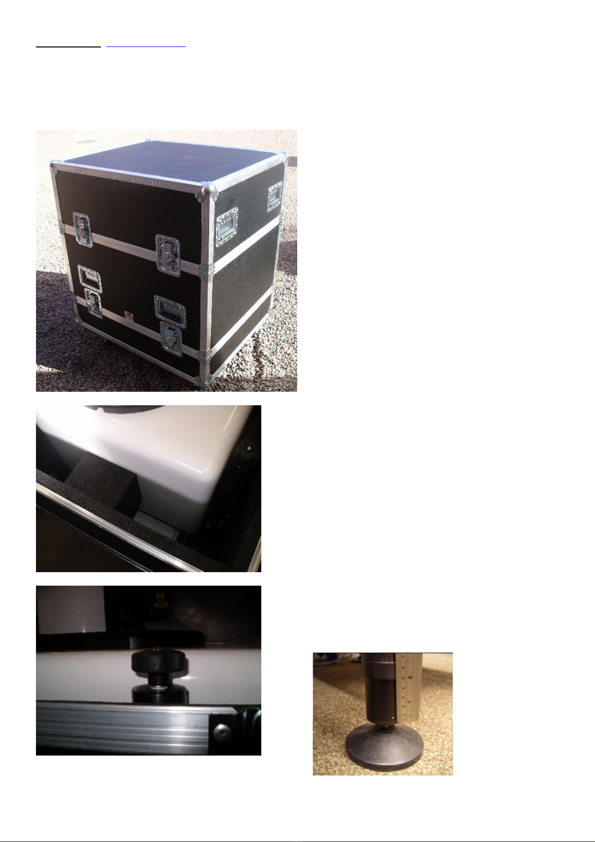
The Lidar must always be transported in the transit case as delivered, or alternatively, another case offering equal or
better protection.
Short movements that can be performed by hand should only be attempted within the guidelines of local manual
handling guidelines.
The Lidar systems are to be handled with the care and attention that would reasonably be expected within the context
of a precision piece of optical equipment.
The Lidar must not be powered whilst being moved or transported.
Operating.
No parts of the Lidar are to be removed or adjusted in any way without the permission of Halo Photonics with the
exception of the lifting handles and mast if fitted. The settings file is not to be modified without permission of Halo
Photonics.
The operating temperature specification is to be observed at all times.
The Lidar should be sited in such a way as to minimise the amount of heat generated by close surfaces (such as
tarmac) or sunlight falling on it. The temperature specification is relevant to the temperature as experienced by the
Lidar, and not a reading taken from a shaded weather station.
The installation and running of software over and above that which was present upon initial delivery (or updated from
time to time by Halo Photonics) must be kept to an absolute minimum. The system’s performance can only be
guaranteed where no 3rd party software has been installed.
If the Lidar loses power for more than 2 hours whilst being operated in an environment where the temperature is
below freezing, then it must be stored at room temperature outside of any transit case or other insulation for at least
10 hours prior to re-deployment.
In cases where the Lidar is to be deployed in an environment within the operating temperature specification, but
outside of the storage temperature specification, an un-interruptible power supply must be used that can supply power
to the Lidar’s battery back-up unit or PCP module for long enough to allow normal power to be reinstated.
The Input voltage to the Lidar must always be within the operating range of 24V DC +/- 10%.
The scanning unit must be allowed to turn freely, and not be impeded by covers, debris or other foreign objects. If
instructed to turn the scanner manually for diagnostic purposes, ensure that the Lidar is either un-powered, or the
motors disabled. The azimuth or elevation movement must not be rotated by hand at a speed to exceeding 10
degrees per second.
It is the responsibility of the user to ensure that all local regulations relevant to operating a Lidar system are adhered
to.

Contents
1. Packing list
2. Unpacking
3. Power requirements and the UPS module.
4. Connections
4.1 24V Bulgin connector
4.2 Air blower and heater assembly
5. Powering up
6. Orientation and levelling
7. Site considerations
8. Controlling the Lidar embedded PC
8.1 Remote connection software.
9. Desktop icons
9.1 Scan Schedule
9.1.1 Variable electronic focus
9.1.2 Stare coordinates
9.1.3 VAD scans
9.1.4 Wind profile scans
9.1.5 User defined scan file
9.1.6 Creating a custom scan file
9.2 Main control software
9.2.1 Real time data display
9.2.2 Data logging
9.2.3 Data file header and data format
9.2.4 Additional displays
9.2.5 Diagnostics tab
9.2.6 Wind profile tab
9.2.7 Stopping the software
10. Shutting down
11. Troubleshooting
12. Routine cleaning
13. Network time synchronisation
14. GPS time synchronisation
15. UDP data broadcasting
16. Typical thermal characteristics
17. Quick start guide and notes
18. Returning a system

1. Packing list. [Back to contents]
1. Lidar unit
2. Separate box or package containing:
1 crossover RJ45 cable.
Spare fuses (10A) for the Lidar, and 2A for UPS module ‘Aux’ output line to blower.
1 spare desiccant cartridge (in a sealed bag)
1 cable to connect the air blower to the Aux connector on the UPS unit (optional).
1 input connector for the UPS module
3. UPS module (optional).
4. Air blower unit (optional).
This picture shows the additional parts.
24V DC UPS module.
Blower unit (optional).

2. Unpacking. [Back to contents]
For transportation, the Lidar and its UPS unit are housed in a transit case that has a removable wheeled base, with all
of the wheels having integral brakes. The transit case with Lidar weighs approximately 110Kg and will need to be
moved according to the appropriate manual handling health and safety guidelines.
The transit case consists of 3 separate pieces. The Lidar is packed fully assembled.
Remove the top section and set it to one
side. The Lidar will now be exposed, and
the integral foam blocks that stop the unit
from moving in transit can be seen.
Note the relative height of the leg tops
compared to the top of the mid-section
transit case. This is the height that the legs
will need to be adjusted to for re-packing –
which is around 50mm.

Check your local manual handling guidelines before lifting, as the unit weighs approximately 60Kg.
Remove the middle section of the case.
There are three locating areas machined
into the legs that match the width of the leg
clamps. The Lidar will be delivered with the
clamps set to the lowest position, and it is
recommended that it be left at this position.
The small pillars with rubber-coned ends
act as support legs when the 4 main legs
are not attached. They prevent the weight
of the Lidar being taken by the cooling
aggregate mounted on the underside of
the main base plate, which would cause
damage.
The feet should all be roughly in the centre
of their positioning recess when the Lidar is
located correctly. Note that the unit will fit
properly in one orientation only.
Lift the unit clear of the transit case tray.
The UPS unit can now also be removed –
along with any other additional parts that
were packed.
Packing the system back up is relatively
straightforward, and is a reverse of the
unpacking procedure. Ensure correct
orientation as shown below.
Scanner
end
Connector
panel end

3. Power requirements and the UPS module. [Back to contents]
The Lidar operates from 24V DC +/- 10%. The supply voltage can sometimes be pulled down to be outside of this
range when the Lidar’s thermal control system is working hard – so it’s best to adjust the input voltage presented to
the UPS module to 25.5V no-load. This will allow the voltage to fall when under load. The Lidar input voltage will be
displayed on the ‘Additional displays’ tab as shown below. The LED will be red if the voltage level falls below 20.5V.
A suitable mains AC to 24V DC power supply unit is recommended for connection to the UPS module (suggestions
are shown on the next page). The output of the PSU be adjusted up to 25.5V DC. It will need to be housed in an
enclosure of suitable IP rating, and have both mains and 24V cable that is safe for use in the working environment.
The Lidar will ship with an optional UPS module that has the correct connections for input to the Lidar. The Lidar
software (when running) will measure the input voltage to the UPS, and if a power cut happens, a warning message
will be displayed in the software tab area, that will warn that a power cut is detected, and show the time remaining until
the Lidar shuts down.
Note that the power cut protection is only active when the software is running and collecting data. The thermal
control circuit is not buffered against power cuts, and the UPS only provides buffered power for the Lidar. If the power
comes back on before the power cut voltage threshold is reached (or the shutdown timer reaches zero), the UPS will
switch back to the 24V main feed, and the system will carry on as normal without shutting down.
I/P Active LED –
illuminated when the unit
has input power.
O/P Active LED – when
lit, 24V is available at the
output connector.
Aux – 24V output.
Connect to the window
blower using the cable
provided.
2-pin Bulgin Maxi
connector

The Lidar draws ~ 6A at 24V DC.
If the active cooling option is fitted, then the additional power draw can draw up to an additional 7A when fully cooling.
The temperature spec of the Lidar with this option is -20 to +40°C.
If the extended cooling option is fitted, then there may be a power draw of up to 14A when fully cooling. The
temperature spec of the Lidar with this option is -20 to +50°C.
The UPS module does not perform any smoothing or regulation of any kind.
A 2-pin Bulgin Maxi connector suitable for 24V DC connection to the UPS unit is provided with the system.
Bulgin Maxi Buccaneer 2 pin socket needed to
connect to the power module input plug. A socket
is supplied with the system.
Part number: PX0911/02/S
+24V DC on the ‘1’ terminal
0V on the ‘2’ terminal
The connector inner (pictured right) is unscrewed
from the main connector body using a left hand
thread. Use a flat blade screwdriver to turn it, and
it will need to be pulled out when unscrewed,
because it has an O’ring seal that will prevent it
from easily coming apart.
Recommended PSU for connection to the 24V DC
input power protection module.
TDK-Lambda HWS600-24 (for the extended cooling option)
Or
QUINT-PS/1AC/24DC/20 (for the passive or active cooling
options)
It is recommended that the no-load voltage of the PSU be turned up to 25.5V before connection to the Lidar
PSU.
The Lidar expects to have a smooth 24V DC +/- 10% at all times. It is the responsibility of the user to ensure that a
suitable 24V DC is provided to the UPS module, and steps should be taken to ensure that the risk of spikes and other
sudden voltage changes outside of the voltage specification are minimised.
A regulator such as this one can be used to provide a clean supply:
http://uk.rs-online.com/web/p/isolated-dc-dc-converters/0491257/
This kind of device is especially useful if a combination of generators and battery banks are being used to power the
Lidar. The output of this unit can be adjusted up to give 25.5V when not connected to the Lidar.
+24V Pin ‘1’

4. Connections. [Back to contents]
From left to right:
RJ45-X – This is for use with an RJ45 crossover cable, which will directly connect the internal PC to another PC.
Power LED and recessed internal PC power button.
The button will act in exactly the same way as a regular desktop PC power button. If the shutdown software has been
run and the PC is switched off, but the system is still powered, then a short press (duration of ½ second) will switch
the PC back on. It is not a reset button.
The power LED will light green when 24V DC is connected to the system. It doesn’t mean that the Lidar components
are powered. There will be a power-up time delay after power is applied. If the fuse (F-1) has blown, the LED will not
be lit. If the time delay is still in progress, the LED will still be lit. When the left most LED close to F-1 and F-2 starts to
flash, it means that the PC is on.
24V DC – this is the 24V DC power inlet coming from the power supply module.
F-1 – 10A 5x20mm fuse for the Lidar circuit.
F-2 – 10A 5x20mm fuse for the heaters and the thermo-electric cooler (TEC) circuit if fitted.
There are 5 small LEDs close to the 2 fuse holders. 1 of them flashes once the internal PC is on and connected to the
control module. This LED is useful when diagnosing the PC’s status.
RJ 45-BB – this is a standard RJ45 connection that can be connected to a regular hub or switch – used to connect the
Lidar to the Internet or a LAN for use with the remote access software.
SVGA – a circular connector requiring the supplied adapter cable to allow connection with a standard SVGA
connector.
Note that the internal PC video resolution is set to be 1280 x 1024 pixels, so the attached monitor will need to be
capable of supporting this resolution.
Mast 1 – Not used
Mast 2 – If the optional GPS module is fitted, then a connector as shown will be fitted; otherwise, the Mast-2
connector will be unwired but in place.
USB-1 and USB-2 are both standard USB 2 connections to the internal PC. They can be used for connecting a
keyboard and mouse.

This picture shows the green GPS
connector, one spare mast connector
another un-wired smaller connector, and
the white purging inlet.
The purge inlet connector will be airtight as
long as the mating input connector is not
installed.
The arrow on the power connector faces
away from the Lidar when it is the correct
orientation. The connector is a ¼ turn
bayonet type. Ensure that it is properly
inserted and locked into position. The
connector may be plastic or metal type.
The metal type still has an orientation
arrow, but it won’t be painted. Ensure that
the connector locks into place when
interfacing. The connector may need to be
supported during the connecting process.
A corresponding enclosure retaining screw labelled
‘Vent’ needs to be removed if a dry air purge of the
system is required (i.e. if the internal humidity of the
system becomes high >60%).
A suitable connector for use with the purge inlet can be
seen here: http://uk.rs-online.com/web/p/hose-
couplings/3872640/
Please contact Halo for advice regarding the purging
procedure if needed.

4.2 Air blower and heater assembly. [Back to contents]
The air blower will help to keep the window clear of dust, water and light snow. An internal heater can be switched on
(the red button), which is controlled via a thermo-switch, which will enable the heater during temperatures lower than
approximately 5ºC. The fan operation is via the blue button.
The blower unit is secured onto the back of the window mount with screw that came with the blower, and a dowel
locates the assembly. It is powered from the UPS box’s ‘Aux’ output and connected using the supplied cable.
The heater draws approximately 20 Watts.
Locating
dowel
Connector
cover

5. Powering up. [Back to contents]
Connect the basic modules as shown in the schematic below. Make all of the connections before switching the power
on. A time-delay device inside the Lidar prevents ‘hot’ power from being applied directly to the internal sub-
components.
*An additional fuse is fitted inside the UPS unit if the extended cooling option is fitted.
Once the UPS module has power and is connected to the Lidar, there may be a short delay before the Lidar starts up
of 10 to 15 seconds. The thermal control system has power 5 seconds or so after power is applied to the Lidar, and so
the external fans may run. Note that if the fans are running, it doesn’t mean that the Lidar itself is also powered, as the
Lidar and thermal control run from separate fuses & time delay units.
Systems fitted with the Active or Extended temperature option.
If either of these options is fitted, the heat exchanger fans will be on all of the time, and soon after power is applied to
the Lidar. The cooling circuit is not covered by the UPS unit, and will go off during a power cut. If the fans are not
operating, and there is not a power cut, then the fuse F-2 may be blown. If fuse F-2 is not blown, then there may be a
fault with the cooling unit, in which case, the Lidar should be powered down to avoid the risk of it over heating.
If the unit has been allowed to cool down to below 15ºC, then additional time will be needed before the unit
can be run. Ideally, the system should be stored at room temperature (20ºC) for at least 24 hours prior to
deployment.
Ensure that a keyboard, mouse and monitor are connected for the first power up.
Optional kit of parts.
Lidar
AC F1 (10A) Lidar input
F2 (10A) Passive & Active
thermal control
Extended cooling system
600W
AC / 24V DC
power supply
Blower
module
A
ux
UPS module
24V DC input
24V DC O/P
*Internal 10A
blade fuse
UPS power
cable

6 Orientation and levelling. [Back to contents]
When the main control software is started, a pitch and roll value will be displayed, and there will be time to level the
system during the setup period.
• An adjustment knob at the top of each leg will extend and retract a telescopic sub-leg to vary the overall leg
length. Adjust the legs in pairs – one end or one side at a time.
• Turn the adjustment knobs clock wise (looking from above) to retract the leg, and counter-clock wise to
extend.
• The pitch and roll sensor has a resolution of 0.1 degrees.
A negative roll number will be displayed
A positive roll number will be displayed
A negative pitch number will be displayed
A positive pitch number will be displayed
All Lidar scan positioning and calculated results will assume
that it is aligned to north as shown. Use the side of the
enclosure, and not the label for reference.
N

7. Site considerations. [Back to contents]
It is highly recommended that the Lidar be deployed on a surface that is not liable to get excessively hot, as the
cooling aggregate (air-flowed heat exchanger) is located on the underside of the base unit. Steps should be taken to
minimise the heat generated underneath the Lidar from direct sunlight - a turfed area is ideal.
Ambient temperatures quoted in the temperature specification of the Lidar are with respect to the air entering the
cooling unit, and not the general ambient temperature on site as measured by a sensor inside a solar shield.
The power supply module should be located directly underneath
the Lidar, and raised off the ground if possible to reduce
exposure to the weather and sunlight.

8. Controlling the Lidar embedded PC. [Back to contents]
There are three methods of controlling the Lidar.
1. Direct connection using a keyboard, mouse and monitor,
2. Network connection using a crossover cable into the RJ45-X connector and a controlling PC with appropriate
remote access software installed,
3. Remote access over a LAN by using another PC on the same LAN running the remote access software.
1. Control using a keyboard, mouse and monitor.
The Lidar has 2 USB ports, and a SVGA connector (via a short interface cable), allowing connection of a keyboard,
mouse and monitor. The monitor resolution is set to 1280 x 1024. A simple USB keyboard without a USB hub is best
used, as it will not require any driver installation.
2. Control using a directly connected PC with crossover cable into the RJ45-X port.
Communication between the Lidar and an attached or LAN connected PC, is achieved by installing
and running the client part of the remote access software found at this address:
http://www.halo-photonics.com/rpcsetup.exe
During installation, you will need to choose to install just the client part.
To remotely connect to the Lidar using a laptop, a crossover RJ45 cable is used. Change your laptop (or other
device) IP settings as follows:
Network settings for an attached PC using the crossover Ethernet cable
IP Address 192.168.0.2
Subnet Mask 255.255.255.0
Default Gateway 192.168.0.1
IP: 192.168.0.2 RJ45-X
Subnet Mask: 255.255.255.0
Default Gateway: 192.168.0.1
Connect your PC to the Lidar using the cross-over cable into the RJ45-X port. Wait for both PCs to find the connection
(usually 10 seconds or so). Now, go to the ‘Remote access software’ step below.
3. Control over a LAN.
It is also possible to attach the Lidar to a LAN using a straight-wired network cable into the RJ45-BB input. The Lidar
is set to acquire an IP address automatically, and the address that is assigned will need to be known in order to use
the remote connection software
LAN Router
RJ45 crossover
Regular RJ45 cable
RJ45-BB

8.1 Remote connection software. [Back to contents]
After the Lidar PC has been given time to boot up, run the client remote PC software on the connected PC. The
following screen will be displayed:
If the connection is made via a crossover cable connected directly to RJ45-X on the Lidar, then the following Remote
computer name is used: 192.168.0.1
If a LAN is being used, then the IP address that has been assigned to the Lidar by the router will need to be entered
instead. It’s also possible that the Lidar will be listed in the drop down menu – if it is, you should be able to use that
instead of having to enter an IP address.
If the PC name isn’t listed, the address that is assigned to the Lidar by your dynamic DNS system must be used. To
find this, it will be necessary to connect to the Lidar using method 1 or 2 as above, so that the IP assigned to the
relevant LAN connection can be observed. This IP address can then be used to connect to the system.
Once the appropriate IP address has been entered as shown above and the connect button clicked, the username
and password dialogue box will appear.
Enter the system serial number for the user name, and the same
reversed for the password. For example, 0102-03 for the username, and
30-2010 for the password including the -character.
Click the ‘Remember password’ check box, so that the username and
password doesn’t have to be entered each time a connection is made, then
click OK to connect.
Use 192.168.0.1 if connected
using a crossover cable into
RJ45-X.
If you are connecting over a
LAN, you will need to enter the
IP address that has been
assigned to the system.
You may also see the computer
name if you select the drop
down menu. If you can see it,
you can select it instead of
entering an IP address.

If the remote PC is physically switched off, or is having a problem connecting to the LAN, then the following message
will be displayed after the ‘Connect’ button is pressed:
If connection is problematic, check that your attached PC is using the correct network settings and that the correct RJ
connection and leads are being used. If the problem persists, follow this procedure:
The first time that a connection is made, the following screen is displayed.
Choose the ‘View screen’ option to view the desktop display of the Lidar PC. The software allows for file transfer
across the connection, as well as an option to view only.
Choose the network connections, choose the
fixed IP connection number (double click), then
choose the support tab. If it's stuck on
acquiring address or is having problems, click
the 'Repair' button. It should then assign the
192.168.0.2 IP address.

At the top of the remote control software window, there are options to Disconnect, Transfer files, Control and View, as
shown below:
Control allows full control over the PC in every way, while View just allows viewing with no interaction.
If the connection configuration and login details are all correct, then the desktop of the Lidar PC will be displayed.
The Transfer Files button will launch a Windows style drag and drop screen with the remote files on the right, and the
local PC on the left. Transfer via this method will be at the connection speed of the LAN. If the Lidar PC is taking data,
then the transfer will be slowed down. Be careful not to transfer or access any data files that are currently being
written to, or sharing violations will occur.
NB. When viewing a remote desktop, it is easy to get confused with respect to which desktop belongs to each PC. It is
recommended to alter the desktop appearance of the attached PC so as to make it sufficiently different to that of the
Lidar PC to minimise the risk of closing down by mistake.
Terminate the software when finished using the Disconnect button.

9 The desktop icons. [Back to contents]
There are 3 software modules related to running the StreamLine Pro Lidar:
Main control software
Shutdown
Scan schedule
The corresponding icons are shown here:
The StreamLine main control software. Double click the icon to load and run.
The scan schedule can be altered during normal control software operation (covered later) and is also accessible
from the desktop at any time. Make sure that no more than one instance of the module is running at any given time.
The Shutdown module is used to power off the internal components when the Lidar will be fully powered down prior
to moving.
Table of contents
Popular Analytical Instrument manuals by other brands

Vigor Equipment
Vigor Equipment V7500/2 operating instructions

Sealey
Sealey VS8199 instructions

AND
AND Density Determination Kit AD-1653 BM Series instruction manual

Leica Geosystems
Leica Geosystems DISTO D110 manual

A&D
A&D LCC12T010 instruction manual

RS Technical Services
RS Technical Services DD LITE 2 Operation manual