Mini Pro Chassis Dyno V1 User manual

CHASSIS DYNO V1
Instruction Manual
REV2.0


2
This dyno is a high-quality analyzing tool intended for persons
aged 18 years and older with previous experience building and
operating Radio Control vehicles. This is not a toy; it is a preci-
sion testing equipment. This dyno is not intended for use by
beginners, inexperienced customers, or by children without di-
rect supervision of a responsible, knowledgeable adult. If you
do not fulll these requirements, please return the kit in unused
and unassembled form back to the shop where you have pur-
chased it.
Before building and operating your dyno, YOU MUST read
through all of the operating instructions and instruction man-
ual and fully understand them to get the maximum enjoyment
and prevent unnecessary damage. Read carefully and fully un-
derstand the instructions before beginning assembly. Contents
of the box may dier from pictures. In line with our policy of
continuous product development, the exact specications of
the dyno may vary without prior notice.
Before Using the Dyno
Soldering IronAllen: 2.0mm
Electronic Speed
Control (ESC)
Vehicle Windows PC
Battery
USING THIS GUIDE
TOOLS REQUIRED
EQUIPMENT REQUIRED
2.0mm
Throttle Controller
R/C Transmitter and Receiver
ESC Controller Sensor*
(Sold by miniPRO)
Servo Tester
Operating System: 7, 8, or 10
(1) USB Port for Dyno
* Additional USB port is required.
OR
OR
* Only for Electric Vehicles
IR Tachometer (Optional)
* Only for Electric Vehicles
OR
Electric Powered
Gas Powered


4
Using this Manual................................................2
Before Using the Dyno .........................2
Tools Required.........................................2
Equipment Required.............................2
Dyno Feature Highlights...................................6
Assemble the Dyno ............................................7
Electronic Connections .....................................8
(miniPRO) Volt. & Current Sensor......8
(Attopilot) Volt. & Current Sensor.. 10
ESC/Servo Controller Sensor........... 11
Driver Installation............................................. 12
Dyno Driver for Windows 7, 8 ......... 12
Dyno Driver for Windows 10 ........... 13
ESC Controller Sensor Driver........... 14
Software Installation ....................................... 15
CONTENTS

5
Dyno Setup......................................................... 16
General Settings .................................. 16
Firmware Update................................. 17
CONTENTS

6
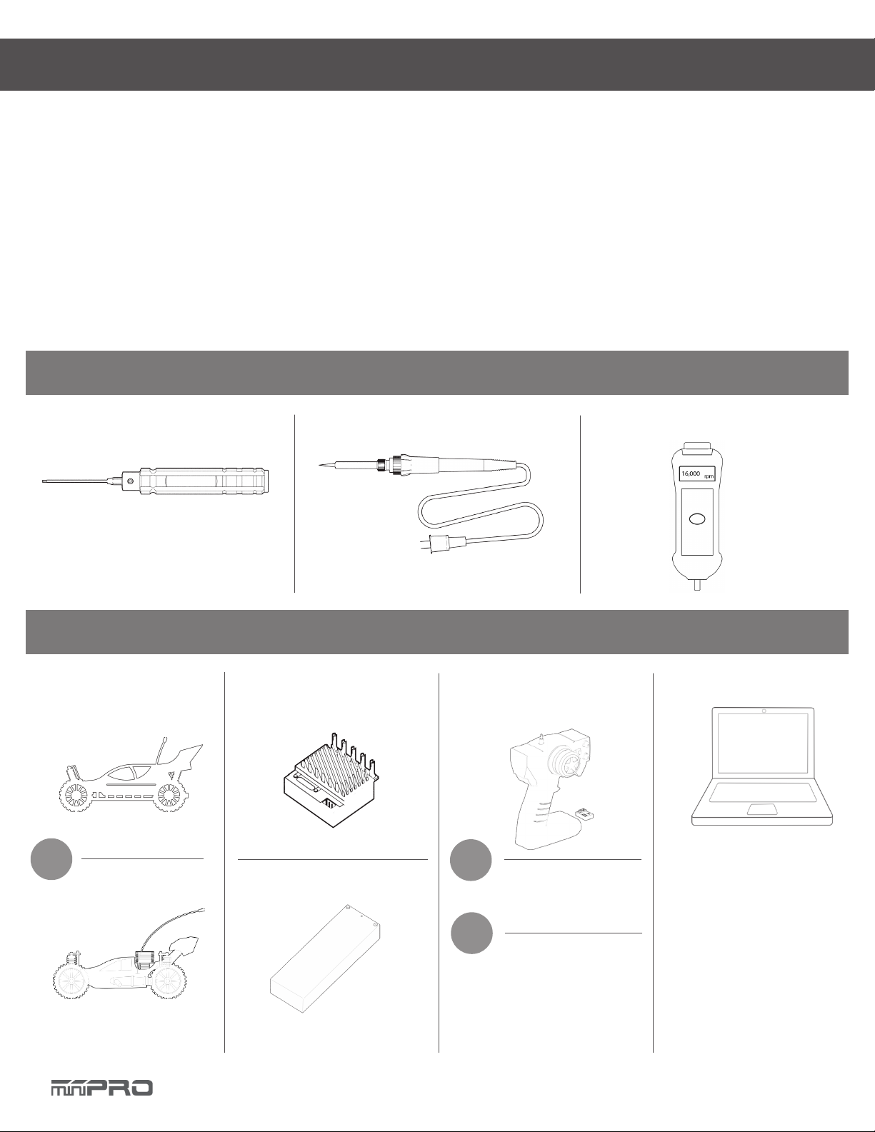
This is a universal chassis dynamometer (dyno) that is ready to test gas or electric vehicles out of the box. Featuring an onboard
electrical board equipped with an optical rpm sensor that measures motor speeds at up to 50,000 rpm. The board is also equipped
with external ports for an external LCD screen, throttle controller, and dierent types of sensors for measuring voltage, current,
and temperature.
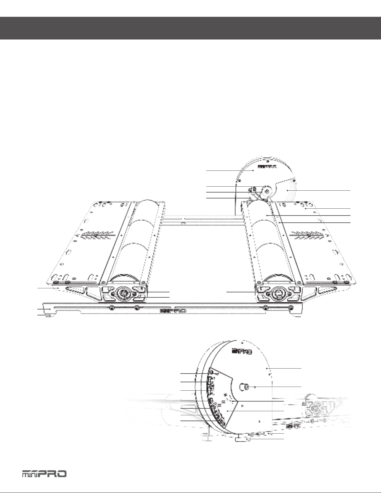
Its adjustable wheelbase and upper deck give the option to test dierent sizes of vehicles (TC, Truck, Buggies, Motorcicles, etc). A
balanced ywheel (inertia mass) is enclosed by a high grade aluminum 6061 cover to provide safety. The ywheel is replaceable,
that means you are not limited to the same load when testing your motors.
This dyno is great tool for motor analysis, ESC (boost) adjustment, brushless sensor adjustment, gearing calculation, acceleration
testing, kV measuring, voltage drop, current draw, power, and torque output analysis.
* May not be included in your kit. Please verify the included accessories in your purchased kit.
DYNO FEATURE HIGHLIGHTS
1. Flywheel Front Cover *
2. Flywheel Pulley *
3. Belt (158T)
4. Flywheel Assy. Stiner
5. Flywheel Window *
6. Upper Deck
7. Roller
8. Roller Cover
9. Side Cover
10. Base Rail
13. Rear Cover *
14. Flywheel *
15. Reset
16. Electronic Board *
17. Flywheel Base Plate for Chassis Dyno
18. Flywheel Bushing Pad
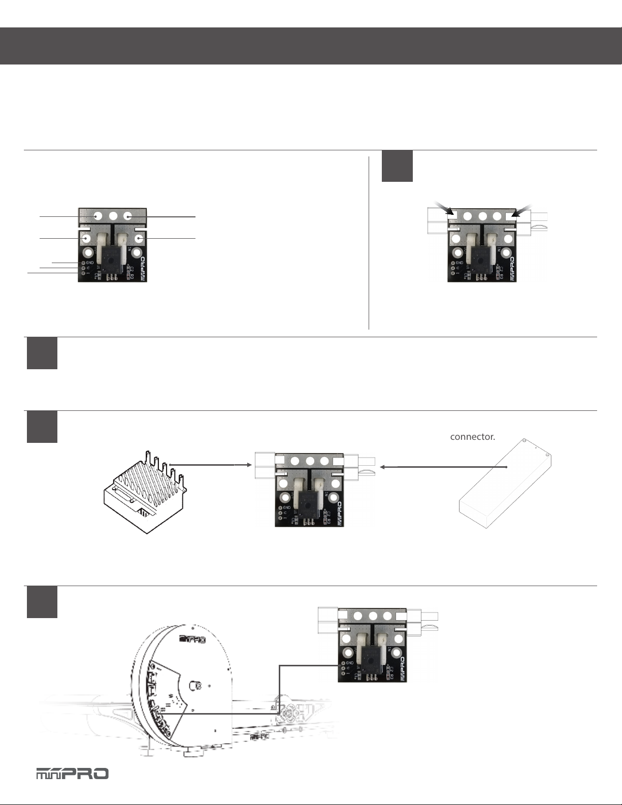
19. Temp. Port #1 (Analog)
20. Temp. Port #2 (Analog)
21. Voltage and Current Sensor Port
22. Micro USB Port
23. LCD/TH/IR Temp. Sensor Port
24. LCD/TH Port
25. Switches
6
19
20
21
22
23
24
13
14
15
16
1
7
9
4
3
2
11
10
12
13
14
5
8
11. Base Bushing Pad
12. Roller End Cap (Free)
13. Roller Holder
14. Roller End Cap (Flywheel)
(For Additional Flywheel Unit)
17
18
24

7
Install Flywheel Assy. Stiner Adjust Wheelbase Install Belt Straps on Vehicle
5 6
Adjust Belt Tension Attach Bushing Pad to Flywheel Assy.
3 4
The dyno its already been pre-assembled. All you need to do is install the ywheel base plate and straps for the vehicle.
NOTE: If you are using your Motor Dyno Flywheel Assy then
you need to remove the belt shield and holder from the dyno.
Install the Flywheel Base Install the Flywheel Assy. and Belt
ASSEMBLE THE DYNO
1 2
NOTE: Do not tighnen the screws.
More
Tension
Less
Tension
Unscrew to set
tension of belt
Uncrew to adjust wheelbase
Adjust Tension of the Belt Straps
7
Uncrew to adjust upper deck and tension of the straps

8
1. (+) Battery Conn.
2. (-) Battery Conn.
3. (-) ESC Conn.
4. (+) ESC Conn.
5. Electronic Board Conn. - Ground
6. Electronic Board Conn. - Voltage
7. Electronic Board Conn. - Current
NOTE: This diagram applies to the 50A, 100A, and 200A sensor.
Please refer to the ESC, Transmitter, and Receiver manufacturers’ instruction manual.
3.1. Connect the ESC’s battery port to the
sensor’s ESC connector. See above sensor
diagram for more information.
3.2. Connect the battery to the
sensor’s battery connector.
3.3. Turn ON the ESC and make
sure it powers on. If the sensor
starts to overheat, disconnect
the battery immediately.
Connect the sensor in the electronic board
with the provided cable.
ELECTRONIC CONNECTIONS
Connect Transmitter, Receiver, and ESC to the Motor
Connect Sensor
Connect Sensor to Electronic Board
2
3
4
Voltage and Current Sensor Diagram Solder Connector
1
3
4
1
2
miniPRO H1 Voltage and Current Sensor Connection
Solder the connectors of your preference
OR 14 gauge wires.
6
7
5

9
1. (-) ESC Conn. (Black)
2. (+) ESC Conn. (Red)
3. Electronic Board Conn. - Current
4. Electronic Board Conn. - Voltage
5. Electronic Board Conn. - Ground
6. (+) Battery Conn. (Red)
7. (-) Battery Conn. (Black)
Please refer to the ESC, Transmitter, and Receiver manufacturers’ instruction manual.
Connect the sensor in the electronic board with the provided cable.
Solder connectors of your preference
OR 14 gauge wires
ELECTRONIC CONNECTIONS
Connect Transmitter, Receiver, and ESC to the Motor
Connect Sensor
Connect Sensor to Electronic Board
2
3
4
Voltage and Current Sensor Diagram
Solder Connector
1
7
62
5
4
3
1
5
4
3
Voltage and Current
Board Diagram
miniPRO A1 Voltage and Current Sensor Connection
1
2
31
2
3
CONT.
3.1. Connect the battery to the sensor’s
battery connector.
3.2. Connect the ESC’s battery port to the
sensor’s ESC connector. See above sensor
diagram for more information.
3.3. Turn ON the ESC and make sure it powers
on. If the sensor starts to overheat, discon-
nect the battery immediately.

10
1. (-) ESC Conn. (Black)
2. (+) ESC Conn. (Red)
3. Electronic Board Conn. - Current
4. Electronic Board Conn. - Voltage
5. Electronic Board Conn. - Ground
6. (+) Battery Conn. (Red)
7. (-) Battery Conn. (Black)
Please refer to the ESC, Transmitter, and Receiver manufacturers’ instruction manual.
Connect the sensor in the electronic board with the provided cable.
Solder connectors of your preference
OR 14 gauge wires
ELECTRONIC CONNECTIONS
Connect Transmitter, Receiver, and ESC to the Motor
Connect Sensor
Connect Sensor to Electronic Board
2
3
4
Voltage and Current Sensor Diagram
Solder Connector
1
7
62
5
4
3
1
5
4
3
Voltage and Current
Board Diagram
Attopilot Voltage and Current Sensor Connection
1
2
31
2
3
CONT.
3.1. Connect the battery to the sensor’s
battery connector.
3.2. Connect the ESC’s battery port to the
sensor’s ESC connector. See above sensor
diagram for more information.
3.3. Turn ON the ESC and make sure it powers
on. If the sensor starts to overheat, discon-
nect the battery immediately.

11
NOTE: This sensor its already been pre-programed to be used with the dyno.
ELECTRONIC CONNECTIONS
ESC Connection
1
ESC/Servo Controller Diagram
Throttle Controller Sensor Connection
1. (-) Ground
2. (+) Positive
3. Signal
4. USB mini-b port
1
2
3
4
CONT.
(-) Ground
(+) Positive
Signal
1. Connect the ESC’s throttle OR the Servo’s
throttle cable to the sensor’s throttle port.
See above sensor driagram for more
OR
(-) Ground
(+) Positive
Signal
ESC Connection (Electrical Powered Vehicles)
Servo Connection (Gas Powered Vehicles).
Connect the Controller Board to PC
2
NOTE: To install driver, please refer to page 14 of this manual.
Servo Connection
NOTE: The throttle sensor can not power a servo. You must use an external battery (6V)
to use the servo.
(Y Servo Connertor (not included))

12
Electronic Board Driver Installation for Windows 7 and 8
DRIVER INSTALLATION
Select “Other Devices”and right click “Un-
known device” and then select “Update
Driver Software”
Take note of the new comunication port
created by the electronic board driver.
4 5
To open the “Device Manager”
3
Download the driver, and connect the dyno
to the pc using the micro-b USB cable.
Go to -->http://minipro.wiki/downloads and download
the latest driver and extract the driver to a new folder.
Open the “Device Manager”
1 2
3.1. Go to --> right-click on Computer.
Click Properties
3.2. In the Properties window, click on Device Manager.
4.1. Select “Browse my
computer...””
4.2. Select “Let me pick
from a list..”
4.3. Select “Have a disk”
and locate the driver
that was saved earlier.
Note: If “Other devices”is not available, then check the
USB connection, or otherwise, It might be possible that
the driver was already been installed by windows.
NOTE: The communication port is required to run the dyno.
Above port number may dier from your pc.
NOTE: When you plug the dyno, a new comunication port
should appear when the driver was installed successfully.
If the driver was automat-
ically installed, it might be
available under “Ports.”
OR

13
Electronic Board Driver Installation for Windows 10
DRIVER INSTALLATION
To open the device manager, right-click on
the Windows Start Button, and click “Device
Manager.”
Take note of the new comunication port
created by the electronic board driver.
3 4
Connect the dyno to the pc using the
micro-b USB cable.
Verify the driver was automatically installed
by opening the “Device Manager.”
1 2
NOTE: The electrinic board driver is installed automatically by
Windows 10; however, you must update the driver..
NOTE: The communication port is required to run the dyno.
Above port number may dier from your pc.
CONT.
NOTE: When you plug the dyno, a new comunication port
should appear when the driver was installed successfully.
Go to -->http://minipro.wiki/downloads and download
the latest driver and extract the driver to a new folder.
4.1. Right Click and select “Update Driver Software”
4.2 Select “Browse my computer...””
4.3. Select “Let me pick from a list..”
4.4. Select “Have a disk” and locate the driver that was
saved earlier.

14
ESC Controller Sensor Driver Installation
DRIVER INSTALLATION
After installing the drivers and plugging the ESC Controller Sensor in via USB, if you go to your
computer’s Device Manager, you should see three entries for the Sensor that look like what is
shown below:
3
Connect the sensor to the pc using the
mini-b USB cable.
Run setup.exe.
The installer will guide you through the
steps required to install the sensor.
1 2
CONT.
Go to -->http://minipro.wiki/downloads
Download the latest driver and extract the driver to a
new folder.
During the installation, Windows will ask you if you want
to install the drivers. Click “Install” (Windows Vista, Win-
dows 7, and later).
4Done!
If you have any questions, please go to support.miniprousa.com and submit a ticket.
NOTE: After you completed a pololu driver installation, the two COM ports might not rename automatically. You must right
click the COM port and select “Update Driver” on each one, or the sensor won’t work properly.

15
Install the Software
SOFTWARE INSTALLATION
Wait a few minutes while “mini D” installs
on your computer.
When installation nishes, click “Close” and
you havesuccessfully installed“Mini D” for
Windows.
5 6
Select the location folder where “mini D”
will be installed, and then select the person
who can use the application. Click “Next.”
Conrm that you want to install“mini D” on
your computer, and click “Next” to continue.
3 4
Download Software
Go to--> http://minipro.wiki/downloads
Next, download the latest software and start the
installation.
Read the Warning Notes and click “Next” if
you agree.
1 2

16
DYNO SETUP
General Settings
SETUP MODE
7
8
9
10
11
12
14
5432
1
5. Factory reset your dyno settings
6. Set sample rate (Frequency)
7. Set the units of your dyno
8. Set the type of ywheel
9. Set the type of dyno
10 Set the ywheel pulley
11. Set the motor pulley (power source)
12. Number of ywheel markers (black tape on the ywheel)
13. Set the current sensor used
14. Voltage Adjustment
15. Port #1: for LCD
16. Port #2: for IR Temp.
17. Port T1: for Loop Temp. Sensor (Temp #1)
18. Port T2: for Loop Temp. Sensor (Temp #2)
19. Setting Switches
20. Reset Button
19
20
Electronic Board
To access the settings of your dyno, you must open the main application and select “ Dyno Settings.”
1Enter Setup Mode
1.1. Open the main application
1.2. Select “Connect Dyno”
1.3. Change only Switch #8 to ON.
1.4. Press the Reset button 1-2 times on the board.
1.5. The Settings application should load automatically.
1.6. (Optional) If the settings application did not load automatically, select “Dyno Settings”
and follow the screen instructions.
Electronic Board
Switches
Reset Button
NOTE: Make sure you have rmware v1.7 or later, and installed the latest application of
miniPRO Dyno before you continue.
3Change your Settings 4Change your Switches
3.1. Select your desired settings
3.2 Select “Save” to complete your settings. 4.1. When nished, select “Disconnect.”
4.2. Change only Switch #8 to OFF.
4.3. Close the Settings Application.
4.4. Done! The main application should load auto-
matically.
13
15
16
17
18
6
1. Connect/Disconnect the dyno to setup mode
2. Save the settings of your dyno
3. Refresh (re-load) the settings of your dyno
4. Update Firmware Icon

17
FIRMWARE UPDATE
General Guide
1Enter Setup Mode
1.1. Change only Switch #8 to ON.
1.2. Press the Reset button on the board.
1.3. Open miniPRO Application.
1.4. Select “Dyno Settings”
3 4
Update the Firmware of your electronic Perform a Factory Reset
Electronic Board
Switches
Reset Button
2Establish a Connection
3.1. Select “Update Firmware.”
3.2. Locate the latest rmware you like to install.
3.3. Select “OK”to continue with the update.
3.4. Select “OK”after the update is completed.
3.5. A Factory reset must start automatically.
3.6. Modify your dyno settings.
3.7. Select “Save” to complete your settings.
3.8. Select “Disconnect.”
3.9. Change only Switch #8 to OFF, press the reset button and
close the application.
4.1. If the automatically factory reset from step 3.5
worked; then go to step no. 5.
4.2. Select “Factory Reset.”
4.3. Select “OK”to continue.
4.4. Select “OK”to after factory reset is completed.
4.5. Modify your dyno settings.
4.6. Select “Save” to complete your settings.
4.7. Select “Disconnect.”
4.8. Change only Switch #8 to OFF, press the reset button
and close the application.
NOTE: Make sure you installed the latest application of
miniPRO Dyno before you continue.
5Done!
If you have any questions, please open a support ticket in support.miniprousa.com
NOTE: Make sure only Switch #8 is ON.
NOTE: Make sure only Switch #8 is ON; otherwise, the factory
reset will not be successful.


Table of contents
Other Mini Pro Motorized Toy Car manuals
Popular Motorized Toy Car manuals by other brands

ANSMANN
ANSMANN 126000004 instructions

THUNDER TIGER
THUNDER TIGER EB-4 S2.5 6242-F Instruction manual & parts catalogue

Kyosho
Kyosho MINI-Z Racer MR-02 RM Type instruction sheet

Reely
Reely Micro Carbon Fighter operating instructions

Rollplay
Rollplay 12V Chevy Silverado W461-C Owner's manual and assembly instructions

Kyosho
Kyosho Inferno GT2 Race Spec Maintenance manual