Minibar Systems Primo 30 User manual

TECHNICAL MANUAL
PRIMO
30
40
Minibar Enterprises AG
Blegistrasse 9
CH-6340 Baar
tel +41 41 767 23 00
tax +41 41 767 23 23
www.minibar.ch
Minibar North America, Inc.
7340 Westmore Road
Rockville, MD 20850
tel +1 301 309 1100
fax +1 301 309 1115
www.minibarNA.com

PRIMO TECHNICAL MANUAL Page
2
Index
Chapter Page
1How a silent chiller works 3
2Fault finding chart 4
3To change silent chiller 5
4To change heater element 7
5To change INTEA junction box 8
6To change a sensor 9
7Junction box / sensor diagnosis 11
8 To change door hinge from right to left 12
9To mount door frames and laminate panel 13
10 To fit a door pull handle 14
11 Lock modification - latch plate, washers 14
12 To change an internal light bulb 15
13 To change a power cable 15

PRIMO TECHNICAL MANUAL Page
3
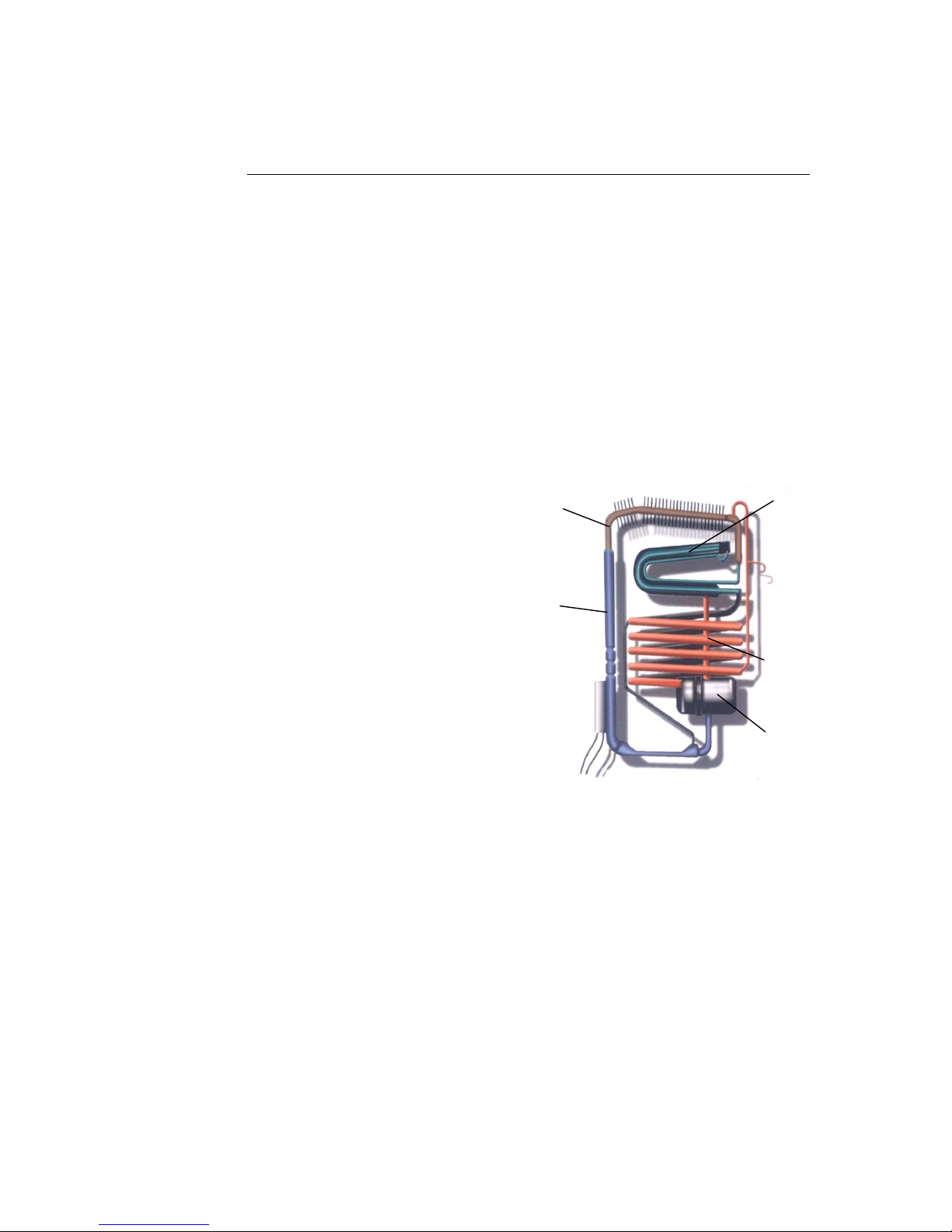
1 How a silent chiller works
Unlike the noisier compression cooling, absorption cooling has no moving parts and
is run by a heating element powered by electricity. It is important to remember that
the heat given off during the absorption and condensation processes must be
dispersed into the surrounding air, and therefore the units require adequate
ventilation space.
Absorption technology
Even though the process is more complex, we will try in a simple way to explain how
the system works. In order to do so, it is important to understand that there are 4
basic parts to an absorption cooling unit, these being:
i. The reservoir-absorber
ii. The boiler pump
iii. The condenser
iv. The evaporator (most
commonly called the chiller)
The system works within a sealed
environment and with a solution
made basically of water, ammonia
and hydrogen.
The boiler pump electrically heats up
and boils the water with a high
concentration of ammonia, which
comes from the reservoir, and that
releases the ammonia now in a form
of gas. The ammonia gas rises to the
upper part of the system, called the
condenser, where, with the help
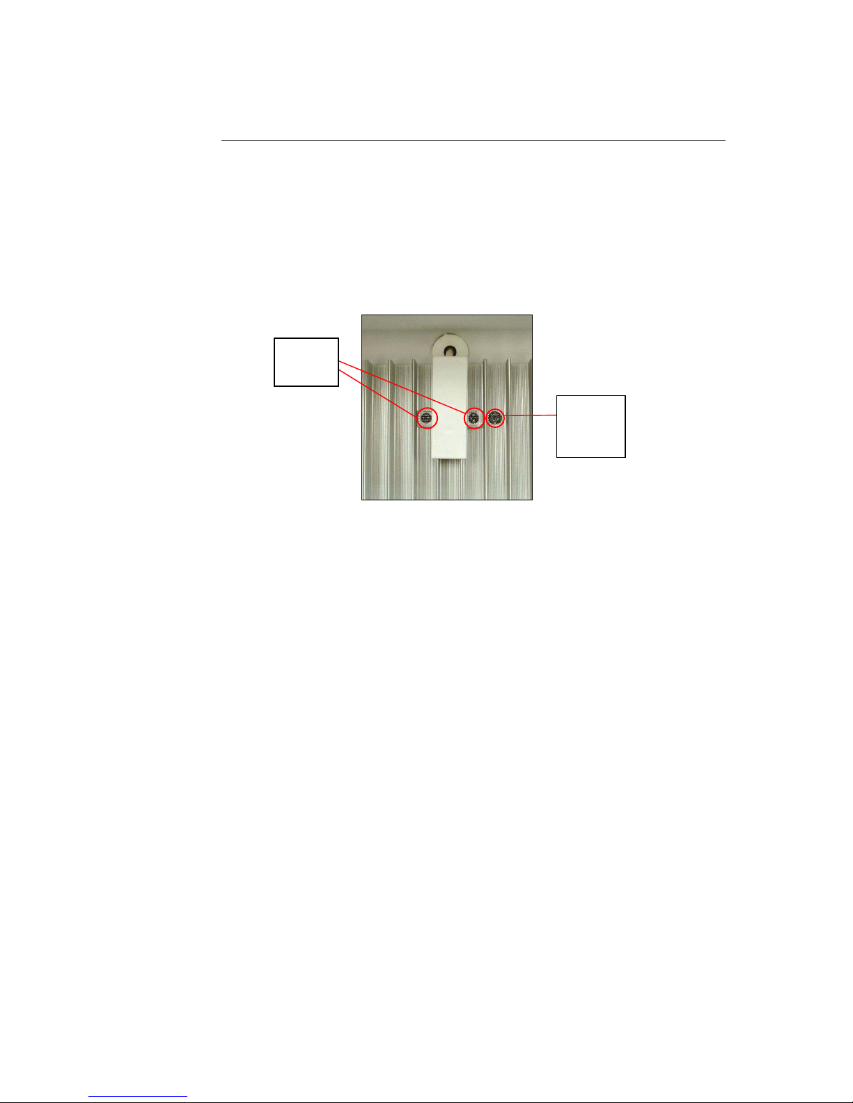
Illustration 1: Absorption cooling unit
of the cooling fins, it causes the temperature to drop, thus condensing only the
ammonia from gas to a liquid form.
This liquid and highly pure ammonia is then moved to the evaporator, where it meets
with hydrogen at different pressure, causing the ammonia to evaporate again. It is a
physical phenomenon that every time we have an evaporation there is a temperature
absorption. In other words, the process pulls the heat from the surrounding area,
consequently cooling the evaporator to a degree that frost is formed in the outer part
of it, and the temperature in the inside of the Minibar is lowered.
The evaporated ammonia, together with the hydrogen, then travel to the absorber,
where we have fairly pure water which, once it encounters the evaporated ammonia
gas, it absorbs it. This process is what gives the system its name, since here water is
absorbing ammonia. By gravity this water-ammonia solution travels through the
absorber coil, absorbing as much ammonia as possible, and ending at the reservoir.
Once in the reservoir, the water with a high content of ammonia passes again to the
boiler pump, where a new cycle then starts.
Boiler
pump
A
bsorbe
r
Reservoi
r
Condense
r
Evaporator

PRIMO TECHNICAL MANUAL Page
4
2 Fault finding chart
? Problem 9Check ÂArea
Power to bar Hotel power supply
Connection to junction box
Bar not cooling
Boiler hot/cold If hot:
Check thermostat setting to
handbook
If cold:
a) Check heater resistance
b) Thermostat function
c) Timer not on defrost cycle
Bar is level Bar warm at rear but not
cooling inside
Overheating at rear
of bar
Ventilation correct Bar overheating at rear
Thermostat setting
Ice build-up in bar
Door closing correctly Products obstructing closing
(door hinge screws loose)
Condition of door seal Damage will allow air entry

PRIMO TECHNICAL MANUAL Page
5
3 To change silent chiller
Rear view of minibar
Minibar junction box
1. Place minibar with door down on flat clean surface
2. Remove power lead from junction box
3. Remove 3 screws securing junction box
4. Cut cable tie securing insulation sleeve to base of silent cooler
5. Carefully remove junction box from rear of minibar
Fixin
g
screws
Heather sleeve
cable tie
Heater cable
Earth wire
Sensor cable
Power cable
Gromet /
sensor cable
Boiler
insulation
sleeve
Cable ties
Junction box
Dri
p
tra
y
4 screws fixing finned
condenser
Screw securing lower
section of chiller

PRIMO TECHNICAL MANUAL Page
6
3 To change silent chiller (continued)
Inside of minibar junction box
6. Disconnect the 2 heater power cables – 2 x Faston connectors
7. Remove 4 screws fixing finned condenser section to rear of bar
8. Remove water drain reservoir at rear base of chiller
9. Remove screw securing lower section of chiller
10. Remove silver paper from rear of evaporator tube to expose styrene insulation.
11. Hold the end of condenser
fins and gently pull chiller
away from cold cube
12. When chiller is released from cold cube,
remove styrene insulation from the rear
of the evaporator tube
13. Remove chiller from the cold cube. continued …
Heater
“Faston”
connectors

PRIMO TECHNICAL MANUAL Page
7
3 To change silent chiller (continued)
To re-mount the silent cooler:
14. Check that there is thermal mastic remaining in the bar aperture to create a
thermal joint.
15. Re-mount the chiller to the cold cube – ensure evaporator tube is fully inserted
into the thermal mastic and aluminium extrusion plate
16. Re-fix top 4 screws into the condenser fin supports.
17. Re-fix lower support screw. Take care to re-fix the earth cable
18. Re-connect heater wires, 2 Faston, to junction box terminals
19. Re-fix junction box, take care with position of cables
20. Secure insulation sleeve to lower part of chiller with cable tie
21. Re-connect power lead and test.
4 To change heater element
Proceed as per Chapter 3, steps 1 - 6
1. Using a test meter check the resistance across the terminals
2. If open circuit proceed to change heater element as follows:
i. Cut 3 cable ties securing boiler insulation sleeve
ii. Using a screwdriver, carefully insert in joint of 2 sections of plastic
housing, at the same time squeeze the area adjacent to the joint.
iii. Remove the 2 sections of the plastic cover.
continued …

PRIMO TECHNICAL MANUAL Page
8
4 To change heater element (continued)
iv. Using a sharp knife, cut the
brown paper outer tape at the
area of joint of insulation
v. Remove the insulation sleeve
vi. Use a flat-blade screwdriver
to release the jubilee fixing
clip on the heater.
(This can then be slid up the
boiler tube and the heater
removed)
To re-mount new heater:
3. Prepare new heater by changing insulation sleeve for cables from old unit (if
not supplied with new)
4. Locate heater to location ring on boiler tube, ensure area is clean before
replacing
5. Re-position jubilee clip and re-tighten (correct torque)
6. Re-fit boiler insulation, using tape to re-seal
7. Re-fit boiler insulation plastic cover. Ensure free passage of cables
8. Fit new cable ties to secure boiler cover
9. Re-connect heater wires, 2 Faston, to junction box terminals
10. Re-fix junction box, take care with position of cables
11. Secure insulation sleeve to lower part of chiller with cable tie
12. Re-connect power lead and test.

PRIMO TECHNICAL MANUAL Page
9
5 To change INTEA junction box
Proceed as per Chapter 3, steps 1 – 6
1. Remove sensor connector wires, the 2 x heater “Faston” connectors, and the
light power cable, if fitted
2. Re-connect wires to the new junction box
3. Re-position the junction box on the rear of the minibar cabinet. TAKE CARE!
Ensure that the cables run through the holes/slots to prevent trapping of cables
4. Re-connect power lead and check control is on position “3” as defined in the
instruction manual.
6 To change a sensor
To remove, proceed as per Chapter 3, steps 1 - 6:
1. Feed the cable up behind the chiller to the point where it enters the cold cube
continued …
Sensor
connector
wires
Heater
“Faston”
connectors
Lamp
connector
(
o
p
tional
)
Gromet /
plastic
inser
t
Sensor
cable

PRIMO TECHNICAL MANUAL Page
10
6 To change a sensor (continued)
2. Using a blunt screwdriver, carefully remove the plastic insert between the cable
and cold cube. (This hole is filled with a sealer to maintain an airtight seal for
the cold cube. Keep the sealer to re-use.)
3. Open the minibar door and remove the 2 x screws securing the clamp to the
evaporator plate. TIP: Cover the defrost drain hole with tape to
prevent screws falling in the tube
4. Remove internal plastic grommet covering hole
5. Carefully pull through the cable from the interior, the socket with cable will
pass the hole with care
6. In some cases it is necessary to remove the evaporator plate (4 screws) to allow
free passage of the cable.
To replace:
7. Feed the new cable plug/cable from inside the minibar
8. Position ready to fix with the clamp
9. Re-fit the internal plastic grommet and adjust cable length to give free
movement
10. Secure the sensor with the clamp and 2 x screws. Remove tape from drain
hole IF used!
11. Re-pack the space around the cable from the rear with the sealant putty and
replace the rear grommet
12. Feed the cable behind the chiller and re-connect socket to the junction box
13. Re-fix junction box.
Screw (4x)
securing
evaporator
plate
2 screws
securing
senso
r

PRIMO TECHNICAL MANUAL Page
11
7 Junction box / sensor diagnosis
Built into the software of the Intea junction box there is a diagnostic mode. This mode
can detect if there is a sensor fault or internal component fault in the junction box.
With setting 3 on the junction box, the test procedure is as follows.
A) Sensor
If the sensor is faulty the JB will supply power to the heater in the following
sequence: 60 seconds ON / 12 seconds OFF
B) Junction Box
If there is a failure of component within the JB the power supply to the heater is
in the following sequence: 80 seconds ON / 16 seconds OFF
Test method
The above tests require that power is applied to the JB. The suggested procedure is
as follows:
1. Remove the power cable from the JB
2. De-mount the JB from the rear of the Minibar
3. Disconnect the wires to the heater/resistance
4. Connect a test lamp 60W bulb and lead with Faston connectors to the heater
terminals on the JB. Check bulb voltage corresponds to JB voltage. Re-fix the
JB to the Minibar.
5. Connect the power lead
6. Turn on power and check the lamp function to identify a condition as per A) or
B) above.
7. If a volt meter is available, the voltage across the terminals of the lamp can also
be measured to check function. To facilitate this a block connector should be
installed in the cable between the lamp holder and the Faston connectors.

PRIMO TECHNICAL MANUAL Page
12
8 To change door hinge from right to left
1. With the door closed,
remove the 2 screws
fixing the top hinge
2. Pull the top of the door away from the minibar to slide the top hinge out of the
slot.
3. Lift door to release from
the bottom hinge pin.
Take care not to lose the 3
washers and the pin.
4. Place the door aside.
5. Remove the 2 screws securing the hinge blanking plate to the left hand hinge
hole.
6. With a sharp point, push out the hinge blanking plate and insert into the right
hand hinge hole.
7. Re-fix with the 2 screws.
8. Remove the bottom hinge pin and washers from the right hand bottom hinge.
9. Place bottom hinge pin and washers into outer hole in the left hand bottom
hinge.
10. Locate left hand door hinge hole on to bottom hinge pin.
11. Fit top hinge pin and plate to left hand top hinge hole on door.
12. Slide top hinge plate into left hand hinge slot.
13. Close door and locate screw holes in hinge plate.
14. Re-fix the 2 screws into the top hinge plate.
15. Check door for correct operation.

PRIMO TECHNICAL MANUAL Page
13
9 To mount door frames and laminate panel
1. Prepare some pieces of laminate of the same thickness, to use as spacers
during assembly
2. Glue the top and both sides of the door with “Bostik” and leave for 10 minutes
to allow the solvent to evaporate. Be careful to put the glue only where
the frame touches, so that there is no glue showing on the gasket. It
is not necessary to glue the frames.
3. Place the door on a
clean, flat surface, and
fit the spacer as per
drawing.
4. Ensure that on the top corners the laminate is well under the frames.
5. Fit the frames, firstly the top, then each side. Ensure that the side frame is well
inside the top, if not, push from the bottom.
6. Secure the frames to the door with elastic bands as per drawing.
7. Drill holes into the door with a 3mm drill, 5mm hole if rivet to be used, use
frames as template.
8. Fix the frames with the screws, Ø 4.2 x 16 self-tapping screws (black plated
with Phillips head). If "Pop" rivet to be used, fit with 5mm rivets.
9. Remove the elastic bands and the spacers. Insert the laminate from the bottom
of the door until it touches the top frame.
10. Fit the bottom frame, drill the door and fix with the screws as above.
Spacers

PRIMO TECHNICAL MANUAL Page
14
10 To fit a door pull handle
The door pull is mounted on the top edge of the Primo door.
1. Mark the position of the handle as per the drawing, 30 mm from the edge
of the door.
2. Drill 3 mm hole, place handle in position and tighten screw.
Screw: Self tapping Ø 4.2 x 9 or 12, black (the handle is black)
11 Lock modification - latch plate, washers
If there is a problem with the lock (Indicator) not securely holding the door closed:
1. Ensure that the bar is fixed into the furniture to prevent lower hinge from
binding.
2. As a further precaution it has been found that 2 other factors can be adjusted:
i. Remove the bottom hinge and insert extra washer(s) on the lower hinge
pin.
Some early production had a very brittle washer which can split. If this is
found, replace the washer with a nylon washer. By adding/removing
washers it is usually possible to adjust out the free-play in the door/lock
location.
ii. If washers cannot solve the problem, remove the lock latch plate, insert a
second latch plate (available from Ghisalba as per the drawing).
Re-fix the existing latch plate and then adjust the washers to obtain the
required results.
Drill hole Ø 3mm
and fix the screw
Side View
30mm Hie
Front View

PRIMO TECHNICAL MANUAL Page
15
12 To change an internal light bulb
1. Disconnect the power to the minibar
2. Open the minibar door
3. Push up the clear plastic cover of the lamp to release the 2 lower clips
4. Pull away the lower edge of the cover and spring out the 2 upper clips
5. Unscrew the lamp bulb. Replace with new. MAKE SURE YOU HAVE THE
CORRECT VOLTAGE!
6. Push the lamp cover back in place
13 To change a power cable
The Primo minibar has a de-mountable power cable using a similar IEC connector as
used in most computers. It is possible to change the lead to meet local needs in USA,
Europe (Schucco), Denmark, Switzerland, UK.
The cable is fixed in place using the cable clamp supplied. It is recommended that
this is used to prevent accidental removal of the cord if it is pulled.
The power cable can be simply plugged/unplugged from the socket in the junction
box and replaced with the required item.
This manual suits for next models
2
Table of contents
Popular Kitchen Appliance manuals by other brands

Philips
Philips HD927X user manual

PARADISE GRILLS
PARADISE GRILLS Professional Pizza Conversion Operator's manual

Mellerware
Mellerware GRAND PRESS 2200W 28560A manual

MagicalButter.com
MagicalButter.com MB2e owner's manual

Mille Rolfe
Mille Rolfe 134474 Assembly instructions

Klarstein
Klarstein VINOVILLA manual