minicopter Diabolo S User manual

minicopter
Manual
Diabolo „S“
Ord.-No. 4950
minicopter
Rheinstahlring 47
34246 Vellmar
Germany
+49 561 988 2800
info@minicopter.de
www.minicopter.de

CongratulationstoyournewDiaboloS,oneofthefastestmodelhelicopters.Thismodelwas
created to reach the highest possible speed under highest possible power with best possi-
ble aerodynamic. The Diabolo S was designed without any comromise. It is extremly small,
the fuselage section has a shape like a symmetrical airfoil to minimize drag. To mount all the
mechanicsandelectronicsintoityouneedsomeinformationswhatistheintentionofthisma-
nual. For the basic mechnical assembly you can also use the classical Diabolo manual. The
assembling technic of the Diabolo and Diabolo S mechanics are very similar. Only the parts
are a little bit different, so there is a part-no. translator attached. This manual was created
to show the special differences of this model including some assembling and justation hints.
Have fun with the assembly and if you have any questions you can send us an e-mail to
info@minicopter.de . We wish you also a lot of fun with the flights of your Diabolo S!
Recommended equipment:
Motor: X-Nova 4535-510 4+4 YY1.6 Pyro 850-50L Pyro 750-50/56 BE
Controller: Kosmik 200 Cool14s YGE320HV16s
Servos: Servos like BLS451 with max 18mm from mounting surface to upside servo arm
FBL-System: BD3-(S)X, AC-3X, V-Stabi
Receiver: 2,4GHz
Flight battery: 2x7s/4400/>60C -2x8s/3850/>60C
Receiver battery: 2s/1600-1800/25-30C (alternativly combine with Kosmik BEC on 8,0V)
Rotorblades: DH691 or DH711
These are components we have tested and we can recommend. Of course you can use
compinents from other manufacturers too, but you must decide individually if they are ok
for the Diabolo S or not.

Maintenance and Security
A radio controlled model helicopter and a speed helicopter especially is not a toy. A mistake
can result in serious accidents and injuries. So keep the following rules always in your mind:
1- Start always with an Idle Up 1 of about 1600 rpm and switch up to Idle Up 2 first when the
model is at least 10 metres high and 20 metres away.
2- Fly high speed passes always with a minimum distance of 50 metres / 150 ft to you. No per-
son should be between you and the model (f.e. modelers with cameras).
3- Keep a minimum flight height of 30 metres. Nore that reaching extreme speeds you reach
at the blades tips the transsonic area which can result in particulary stalls on the airfoil. To res-
cue the model you need a minimum height to react and start actions to save the model.
4- Fly with discipline. Do not fly more passes that you have calculated before. Do never fly
deep and closed to enlarge the impressions of spectators.
5- Do not fly with crosswind that press the model in your direction. All aerodynamic bodies,
also the Diabolo S are sensitive against crosswinds and can move cross to you more than you
have expected.
6- Do not go over your personal limit. High speed flight needs a lot of training and experience
that you must learn first. With increasing speed you must calibrate your FBL system perhaps
different, modify parametres like headspeed and pitch.
7- Do not fly faster and only so far away how your eyes allow this. The model can climb after a
pass very fast heights and distances that are difficult to observe. So be careful.
8- The most important rule: Do never start if you are not absolutely sure that everything is ok!
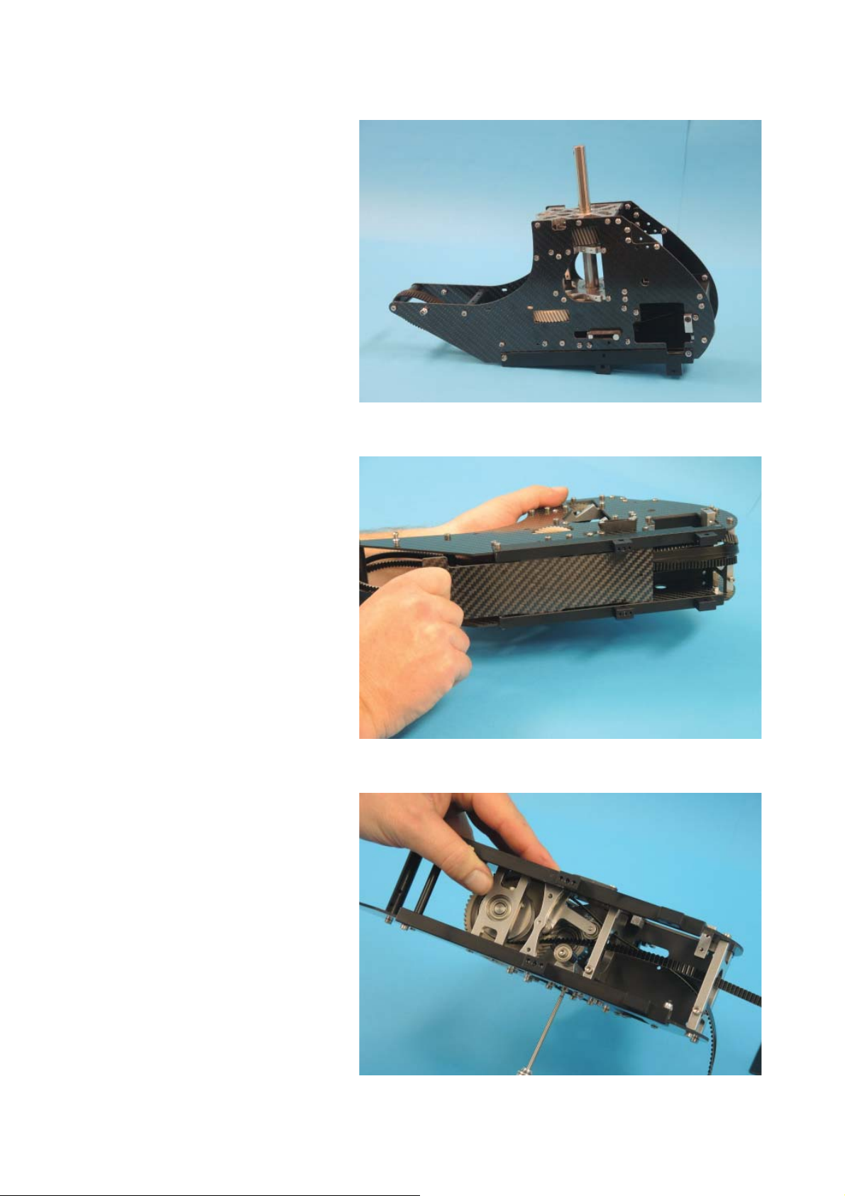
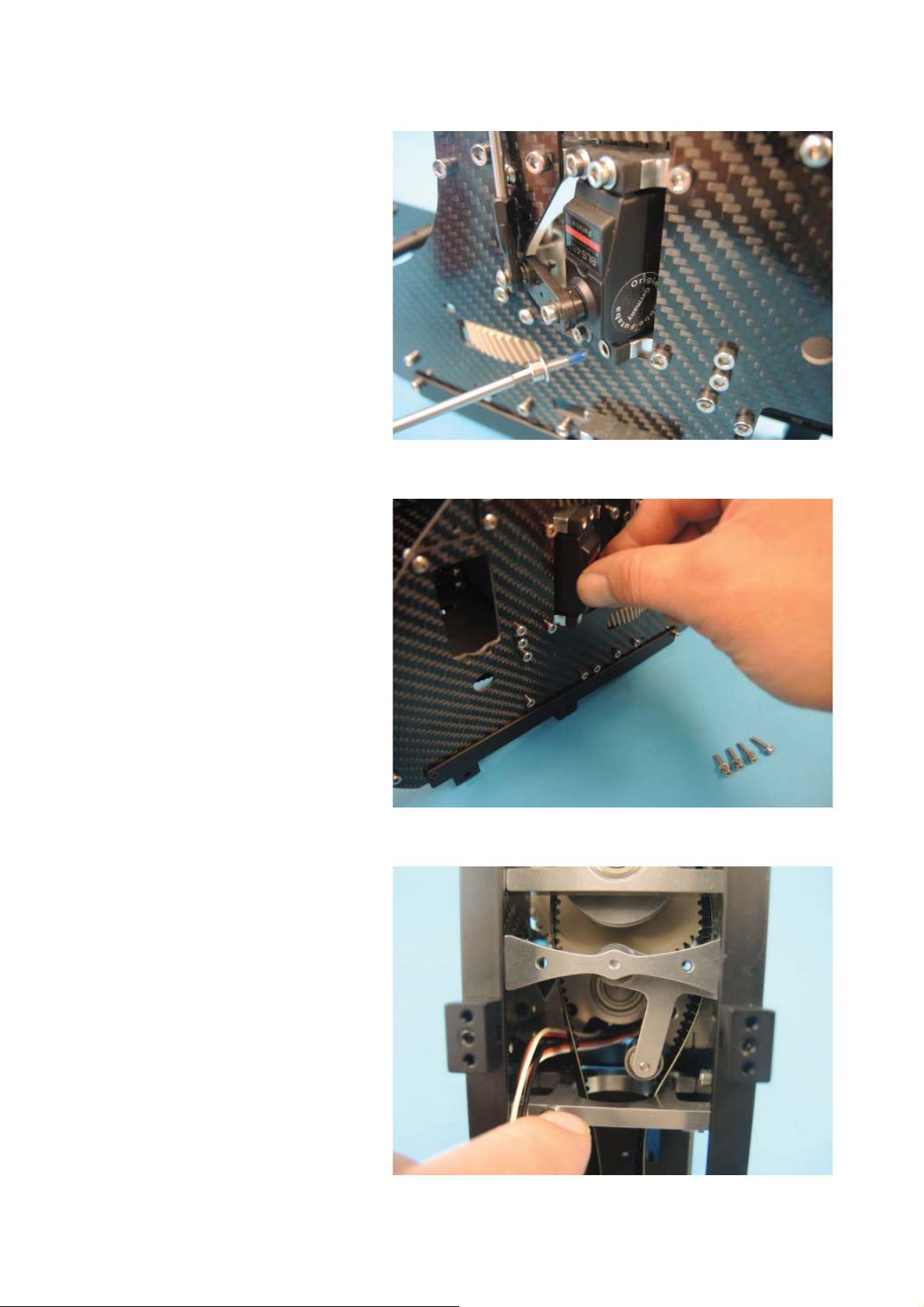
Maintenance: The Diabolo S was designed for a high standard reliability and durability. But
that does not mean that you must not do any maintenance. After each flight you should do a
check of ALL mechanical parts. Look for loose screws, cables. Check the bearings, gears, all
electric connections, ball joints, antennas.
The second stage gear must be lubricated. Calculate that after each flight you must add two or
three drops from the oil bottle that is in the kit. In each casee it may never run dry. Avoid to fly
in a dusty environment and if you do that then climb up fats from the ground to minimize dust
in the body.
Pitch adjustments: -6°/+5°/+16°
Idle up 1: 1600 rpm Idle up 2: 2200 rpm Idle up 3: Max rpm
Because we cannot control what a modeler is doing with the model we cannot give any war-
ranty.
Vellmar, in February 2014

Part-No. translator Diabolo - Diabolo S
The following parts are similar between both models but not the same. So use this tarnsla-
tor to find the right part no. if you need any spare.
D1 upper left side frame D258
D2 upper right frame D259
D14 mainshaft D220
D16 lower mainshaft bearing plate D272
D17 Upper bearings plate D271
D70 First stage bearing D243
D71 Mainshaft bearing D230
D13 Main gear wheel D274
D15 distance bush mainshaft D224
048 washer shim 0,1mm D231
033 washer shim 0,2mm D232
D7 gear wheel first stage D7a
D5 first stage distance bush D195
D4 main gear pinion D275
D21 tailboom D280
D46 tail pulley D249
D43 tail gear housing D246
068 tailshaft bearing D247
D47 distance shim D250
044 washer shim 0,1mm D46
D45 tailrotor shaft D245
D18 roll servo holder D273
D28 vertical U-Profile D284
D25 belt tensioner arm D261
D34 shock absorber D262
902 landing skids pair D281
D20 distances elevator servo D270
D89 elevator servo screws D83
D23 rear tailservo mounting block D283
D50 swashplate D226
D58 conic distance bush swashplate D233
D104 screw for D58 D102
D91 screw for distance bush D90
D32 distance bush for swash holder D244
D90 screw for D32 D88
D52 mainrotor hub D229
521 feather spindle D235
586 damping insert D236
047 washer shim 0.5mm 757
071 blade grip bearing D238
509 inner grip bush D239
100 thrust bearing D237
052 washer shim feather spindle D242
034 spindle screw D234

538 mainblade grip D240
593 swash driver distance bush D241
110 tailrotor hub D255
979 conic ring D257
1471 tailslider D256
D49 tail bellcrank D264
347 tailslider guidance bush D288
D155 battery plate D269
- Battery plate stopping block D279
The following parts are new and not in the normal Diabolo manual:
D191 support bearing block
D263 holder for D262
D265 L-Profile left
D266 L-Profile right
D267 front skid holder
D268 rear skid holder
D276 canopy connector 3.5mm
D277 canopy connector 4mm
D278 triangle plate CF
D285 maingear lubrication oil 60ml
D286 mounting bush Kosmik
D287 battery tray stopping block

This is the mechanic in
delivery condition.
Remove the battery plate for
the rear flight battery.
Remove the roller. Later the
roll servo cables will be placed
between the spacers under the
roller.

Remove the rear tail servo
holder. Do not lose the screw.
Keep both parts together.
Open bag 7 and sort the parts
on the table.
Start with mounting the fly-
barless system. We recom-
mend to mount it directly on
the U-profile. On the picture
we mount a Bavarian Demon
HC3X.

Mount the ball joints on the
servo arms using for each
arm a hex lense screw M3x16
D103, two 3mm washers 002
and a M3 lock nut 008. Attach
two rods D54 with four ball
joints D72.
The overall length of both roll
servo rods should be 103 mm
about.
Insert the left roll servo into the
frame. Look that the cable is
going downwards.

Fix the servo with four hex
screws M3x12 D84 and
washers 002 using Loctite
on the screw thread. Do not
overtighten the screws. Then
the thin bushes in the rubber
blocks would be compressed.
Now mount the right roll servo
in the same way.
Look that both cables are
placed as shown.

The screws are easier to
mount if you look before atta-
ching the screws into the hole
to what direction the thread is
going about. The rubber blocks
are elastic so during mount it
is not always guaranteed that
the thread is also in the center
of the bush. After attaching all
screws it will be centered.
Mount the screws using Loctite
on the thread.
Two plastic blocks must be
mounted on the elevator servo
with four hex screw D84 and
washers 002 (use no Loctite!).
Note that the block D270 on
the cable side is 2 mm higher
than the block D299 on the
other side.

Blocks in mounted condition.
Length of elevator servo arm
should be 102.5mm.
The small triangle carbon part
makes it a little bit difficult to
insert the servo but a servo like
Futaba BLS451 definetly fits. If
you have problems then loose
for the servo mount the three
lense screws of the triangle a
little bit and tighten them again
when the servo is placed.

Mount the upper block with
two hex screw M3x10 D83 (no
Loctite!). Do not overtight the
threads in the blocks.
For the lower block use two
hex screws M3x8 D82.
Cut the rubber grommet D80
with a knife and insert the ser-
vo cable. Then insert the servo
connector into the hole of the
CF frame and finally press the
grommet in.

All servo cables should be un-
der the mechanic right now.
Now mount the roller block.
The best is to attach first the
screws and from inside the
spacers. Then add the roll
servo cables between and add
Loctite on the screws threads.
Then add the roller block.
During tightening have an eye
on it that the cables are not
squeezed beteen the contact
planes of the parts. The re-
sult (with a contacted impulse
cable) could be sudden move-
ments of the servo arms.
For better identification when
you plug in the connectors in
the flybarless system it makes
sense to add a „R“ and „L“ on
the roll servo cables.

Install the cables as shown on
the pic.
The tail servo holders should
be mounted with four hex
screws M3x12 D84 and
washers 002 using Loctite.
Note that the block with the
countersunk hole is placed on
the cable side. The fuselage is
very narrow at this area so a
countersunk screw is necessa-
ry there.
Insert the tailservo in the
shown way. A MKS 980 servo
just fits into the frame, also
of course the smaller Futaba
BLS 251/256. On the servo
the arm must be attached with
a screw using Loctite. If you
are not sure if the arm is in the
right position on the toothed
shaft then do not mount the
two screws that fix the servo
mounts on the frame. Tighten
them after FBL calibration, but
do not forget it!

If you are sure the servo arm is
in correct position then add the
countersunk screw M3x12 471
on the rear servo block using
Loctite.
Accordingly mount the front
block with a hex screw M3x14
D85 using Loctite.
Now plug in the connectors
into the FBL system.
Important: After you have
mounted all plugs in the sys-
tem fix them with hot glue that
they cannot come out under
vibrations. This suggestion is
independent from the type of
used flybarless system.

Press all cable length that is
not necessary under the U-
profile. There is a lot of space
for cables and the upper side
looks very nice without unne-
cessary cables.
Attach a piece of double sided
foam (about 3mm or 1/8“) on
the reiceiver.
Place the receiver, here a
Futaba 6303SB, as shown. If
your receiver is bigger you find
alternative places under the U-
profile, outside the frame or on
the additional gyro platform.

Add now the swashplate body
D226 on the justation help
D289 on the mainshaft.
Mount the left servo rod using
a hex lense screw M3x12
D102 and a conic spacer
D233. For maximum safety
here add righ Loctite on BOTH
threads and remove unneces-
sary Loctite at once.
The swash plate guidance is
made from a hex screw M3x25
D90, a brass spacer D55 and
a conic bush D233. Add also
with rich Loctite on both ends.

Check that brass bush is mo-
ving free in the guidance after
tightening the screw.
Add the swash guidance D32
using two hex screws M3x25
D90 and two spacers D244
using Loctite.
Have a final check that the
swash guidance is parallel to
the mainshaft.

Now prepare the rotorhead.
Open bag 8 and sort the parts
on the table. The big washer
shims are not necessary and
only added for individual tighte-
ning of the spindle.
The length of the linkages is
about 62 mm.
Attach the linkages on the
arms with two hex lense
screws M3x12 D102 using
Loctite. Note that the joint with
the left thread (marked with a
small ring) is upwards (moun-
ted on the blade arm).

Add the two joints bolts M3x4
076 on the swashplate using
Loctite.
Mount the swashdriver arms
D65 as shown in the pic using
Loctite. The screw for moun-
ting on the hub is a hex lense
M3x10 D101 with a washer
3x6x0.2 455, the outer one is
a M3x12 D102 that is screwed
into the bush D241. Finally the
joint 385 is fixed with a cross
screw M2.5x12 509 (no Loc-
tite!). Finally mount both units
on the hub using Loctite.
Put the rotorhead on the
mainshaft. Do not forget to
loose the two black M3 screws
in the hub before.
Table of contents
Other minicopter Toy manuals

minicopter
minicopter Diabolo Black User manual

minicopter
minicopter JOKER CX User manual

minicopter
minicopter Maxi-Joker User manual

minicopter
minicopter mini-Joker User manual

minicopter
minicopter Diabolo 2018 User manual

minicopter
minicopter Diabolo 800+ User manual

minicopter
minicopter Maxi-Joker 2 Installation and user guide

minicopter
minicopter Acrobat User manual

minicopter
minicopter Diabolo 600 User manual

minicopter
minicopter Diabolo 700 UL User manual