manuals.online logo
Brands
  1. Home
  2. •
  3. Brands
  4. •
  5. MINN KOTA
  6. •
  7. Engine
  8. •
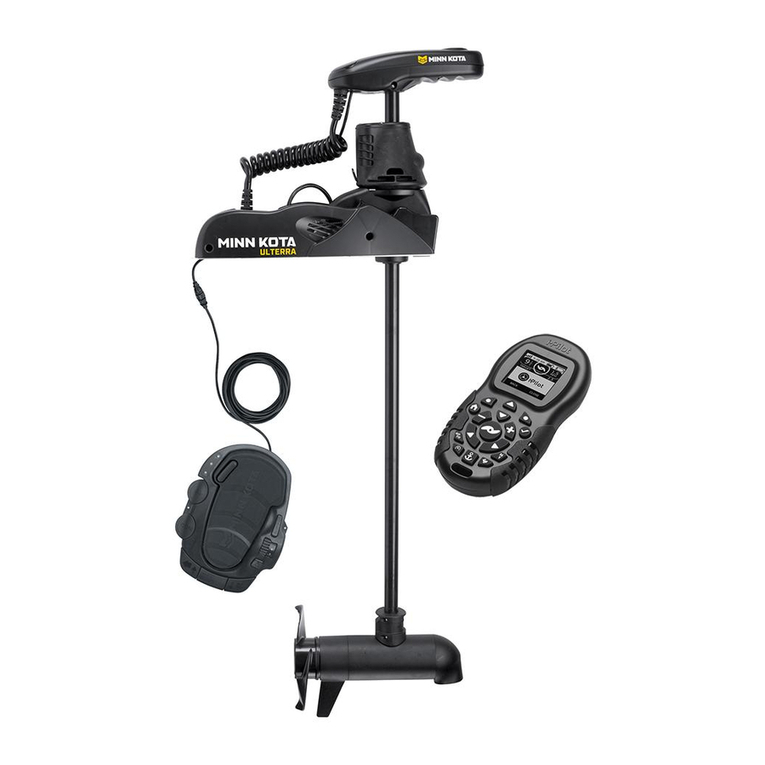
  9. MINN KOTA ULTERRA User manual

MINN KOTA ULTERRA User manual

ULTERRA™
BOW-MOUNT TROLLING MOTOR
Owner's Manual
2 | minnkotamotors.com ©2023 Johnson Outdoors Marine Electronics, Inc.
INTRODUCTION
EXAMPLE
THANK YOU
Thank you for choosing Minn Kota. We believe that you should spend more time fishing and less time positioning your boat. That’s why
we build the smartest, toughest, most intuitive trolling motors on the water. Every aspect of a Minn Kota trolling motor is thought out and
rethought until it’s good enough to bear our name. Countless hours of research and testing provide you the Minn Kota advantage that can
truly take you “Anywhere. Anytime.” We don’t believe in shortcuts. We are Minn Kota. And we are never done helping you catch more fish.
REGISTRATION
Remember to keep your receipt and immediately register
your trolling motor. A registration card is included with your
motor, or you can complete registration on our website at
minnkotamotors.com/register.
SERIAL NUMBER
Your Minn Kota 11-character serial number is very important. It
helps to determine the specific model and year of manufacture.
When contacting Consumer Service or registering your product,
you will need to know your product’s serial number. A duplicate
copy of your serial number label has been included, which can also
be entered into the One-Boat Network® App for future reference.
MOTOR INFORMATION (For Consumer Reference Only)
Model: ___________________________________________________________________________________________________
Serial Number: _____________________________________________________________________________________________
Purchase Date: _____________________________________________________________________________________________
Store Where Purchased: ______________________________________________________________________________________
Made for iPhone® 11 and iPhone X
For updated iOS, Humminbird® and Minn Kota® compatibility, visit minnkotamotors.com
Use of the Made for Apple badge means that an accessory has been designed to connect specifically to the Apple product(s) identified
in the badge, and has been certified by the developer to meet Apple performance standards. Apple is not responsible for the operation
of this device or its compliance with safety and regulatory standards. iPhone is a trademark of Apple Inc., registered in the U.S. and other
countries. The trademark "iPhone" is used in Japan with a license from Airphone K.K.
Android™ is a trademark of Google LLC. The Android™ robot is reproduced or modified from work created and shared by Google and
used according to terms described in the Creative Commons 3.0 Attribution License.
Made for
Android
Android
™
™
NOTICE: The serial number on your Ulterra is located
inside the mount near the motor rests.
NOTICE: Do not return your Minn Kota motor to your retailer. Your retailer is not authorized to repair or replace this unit. You may obtain
service by: calling Minn Kota at (800) 227-6433; returning your motor to the Minn Kota Factory Service Center; sending or taking your
motor to any Minn Kota authorized service center. A list of authorized service centers is available on our website, minnkotamotors.com.
Please include proof of purchase, serial number and purchase date for warranty service with any of the above options.
minnkotamotors.com | 3©2023 Johnson Outdoors Marine Electronics, Inc.
TABLE OF CONTENTS
SAFETY CONSIDERATIONS ......................................................................................................... 4
WARRANTY ............................................................................................................................ 5
KNOW YOUR BOAT.................................................................................................................... 6
FEATURES.............................................................................................................................. 7
INSTALLATION......................................................................................................................... 8
Installing the Ulterra......................................................................................................... 9
Identifying Trolling Motor Features and their Associated Cables ...................................... 15
Critical Cable Routing..................................................................................................... 16
Feature and Cable Management..................................................................................... 17
Dual Spectrum CHIRP ................................................................................................ 17
Built-in MEGA Down Imaging ...................................................................................... 21
Advanced GPS Navigation .......................................................................................... 26
Securing Accessory Cables ......................................................................................... 31
BATTERY & WIRING INSTALLATION............................................................................................. 36
Boat Rigging & Product Installation ................................................................................ 36
Conductor Gauge and Circuit Breaker Sizing Table.......................................................... 36
Selecting the Correct Batteries ....................................................................................... 37
Additional Considerations............................................................................................... 37
Connecting the Batteries in Series .................................................................................. 38
MOTOR WIRING DIAGRAM........................................................................................................ 40
USING & ADJUSTING THE MOTOR .............................................................................................. 41
Mount Features.............................................................................................................. 41
Motor Adjustments......................................................................................................... 43
Installing an External Transducer ................................................................................ 43
Changing the Prop Orientation .................................................................................... 44
Adjusting the Lift Belt ................................................................................................. 47
Greasing the Latch Pin and Power Tilt Motor Shaft ...................................................... 47
Stowing from the Ulterra Motor ................................................................................... 48
Trim/Stow Reset Procedure......................................................................................... 49
Manually Stowing the Ulterra ...................................................................................... 50
ADVANCED GPS NAVIGATION WIRELESS REMOTE .......................................................................... 54
ONE-BOAT NETWORK APP........................................................................................................ 58
USING THE FOOT PEDAL .......................................................................................................... 61
Controlling Speed & Steering with the Foot Pedal ............................................................ 61
Modes............................................................................................................................ 61
Foot Pedal Adjustments.................................................................................................. 64
Stowing and Deploying the Motor with the Foot Pedal .................................................. 64
Adjusting the Depth of the Motor (Trim) with the Foot Pedal ........................................ 65
SERVICE & MAINTENANCE ....................................................................................................... 66
Propeller Replacement................................................................................................... 66
General Maintenance ..................................................................................................... 67
Troubleshooting ............................................................................................................. 67
Advanced Troubleshooting.......................................................................................... 69
For Further Troubleshooting and Repair ...................................................................... 76
COMPLIANCE STATEMENTS...................................................................................................... 77
PARTS DIAGRAM & PARTS LIST ................................................................................................. 79
4 | minnkotamotors.com ©2023 Johnson Outdoors Marine Electronics, Inc.
SAFETY CONSIDERATIONS
Please thoroughly read the user manual. Follow all instructions and heed all safety and cautionary notices. Use of this motor is only
permitted for persons that have read and understood these user instructions. Minors may use this motor only under adult supervision.
WARNING
You are responsible for the safe and prudent operation of your vessel. We have designed your Minn Kota product to be an accurate
and reliable tool that will enhance boat operation and improve your ability to catch fish. This product does not relieve you from the
responsibility for safe operation of your boat. You must avoid hazards to navigation and always maintain a permanent watch so you can
respond to situations as they develop. You must always be prepared to regain manual control of your boat. Learn to operate your Minn
Kota product in an area free from hazards and obstacles.
WARNING
Never run the motor out of the water, as this may result in injuries from the rotating propeller. The motor should be disconnected from
the power source when it is not in use or is othe water. When connecting the power-supply cables of the motor to the battery, ensure
that they are not kinked or subject to chafe and route them in such a way that persons cannot trip over them. Before using the motor
make sure that the insulation of the power cables is not damaged. Disregarding these safety precautions may result in electric shorts
of battery(s) and/or motor. Always disconnect motor from battery(s) before cleaning or checking the propeller. Avoid submerging the
complete motor as water may enter the lower unit through control head and shaft. If the motor is used while water is present in the lower
unit considerable damage to the motor can occur. This damage will not be covered by warranty.
WARNING
Take care that neither you nor other persons approach the turning propeller too closely, neither with body parts nor with objects.
The motor is powerful and may endanger or injure you or others. While the motor is running watch out for persons swimming and for
floating objects. Persons who lack the ability to run the motor or whose reactions are impaired by alcohol, drugs, medication, or other
substances are not permitted to use this motor. This motor is not suitable for use in strong currents. The constant noise pressure level of
the motor during use is less than 70dB(A). The overall vibration level does not exceed 2,5 m/sec2.
WARNING
When stowing or deploying the motor, keep fingers clear of all hinge and pivot points and all moving parts. In the event of unexpected
operation, remove power leads from the battery.
WARNING
It is recommended to only use Johnson Outdoors approved accessories with your Minn Kota motor. Using non-approved accessories
including to mount or control your motor may cause damage, unexpected motor operation and injury. Be sure to use the product and
approved accessories, including remotes, safely and in the manner directed to avoid accidental or unexpected motor operation. Keep all
factory installed parts in place including motor and accessory covers, enclosures and guards.
minnkotamotors.com | 5©2023 Johnson Outdoors Marine Electronics, Inc.
WARRANTY
WARRANTY ON MINN KOTA FRESHWATER TROLLING MOTORS
Minn Kota Freshwater Trolling Motors - Limited Lifetime Warranty On Composite Shaft And Limited
Two-Year Warranty On The Entire Product
Johnson Outdoors Marine Electronics, Inc. (“JOME”) extends the following limited warranty to the original retail purchaser only. Warranty coverage is
not transferable.
Minn Kota Limited Two-Year Warranty on the Entire Product
JOME warrants to the original retail purchaser only that the purchaser’s new Minn Kota freshwater trolling motor will be materially free from defects in
materials and workmanship appearing within two (2) years after the date of purchase. JOME will (at its option) either repair or replace, free of charge,
any parts found by JOME to be defective during the term of this warranty. Such repair, or replacement shall be the sole and exclusive liability of JOME
and the sole and exclusive remedy of the purchaser for breach of this warranty.
Minn Kota Limited Lifetime Warranty on the Composite Shaft
JOME warrants to the original retail purchaser only that the composite shaft of the purchaser’s Minn Kota trolling motor will be materially free from
defects in materials and workmanship appearing within the original purchaser’s lifetime. JOME will provide a new composite shaft, free of charge, to
replace any composite shaft found by JOME to be defective during the term of this warranty. Providing a new composite shaft shall be the sole and
exclusive liability of JOME and the sole and exclusive remedy of the purchaser for breach of this warranty; and purchaser shall be responsible for
installing, or for the cost of labor to install, any new composite shaft provided by JOME.
Exclusions and Limitations
This limited warranty does not apply to products that have been used in saltwater or brackish water, commercially or for rental purposes. This limited
warranty does not cover normal wear and tear, blemishes that do not aect the operation of the product, or damage caused by accidents, abuse,
alteration, modification, shipping damages, acts of God, negligence of the user or misuse, improper or insucient care or maintenance. DAMAGE
CAUSED BY THE USE OF OTHER REPLACEMENT PARTS NOT MEETING THE DESIGN SPECIFICATIONS OF THE ORIGINAL PARTS WILL NOT BE
COVERED BY THIS LIMITED WARRANTY. The cost of normal maintenance or replacement parts which are not in breach of the limited warranty are
the responsibility of the purchaser. Prior to using products, the purchaser shall determine the suitability of the products for the intended use and
assumes all related risk and liability. Any assistance JOME provides to or procures for the purchaser outside the terms, limitations or exclusions of this
limited warranty will not constitute a waiver of the terms, limitations or exclusions, nor will such assistance extend or revive the warranty. JOME will not
reimburse the purchaser for any expenses incurred by the purchaser in repairing, correcting or replacing any defective products or parts, except those
incurred with JOME’s prior written permission. JOME’S AGGREGATE LIABILITY WITH RESPECT TO COVERED PRODUCTS IS LIMITED TO AN AMOUNT
EQUAL TO THE PURCHASER’S ORIGINAL PURCHASE PRICE PAID FOR SUCH PRODUCT.
Minn Kota Service Information
To obtain warranty service in the U.S., the product believed to be defective, and proof of original
purchase (including the date of purchase), must be presented to a Minn Kota Authorized Service
Center. Go to www.minnkotamotors.com/support/service-providers/locate to find a Minn Kota
Authorized Service Center. Any charges incurred for service calls, transportation or shipping/
freight to/from the Minn Kota Authorized Service Center, labor to haul out, remove, re-install or
re-rig products removed for warranty service, or any other similar items are the sole and exclusive
responsibility of the purchaser. Products purchased outside of the U.S. must be returned prepaid
with proof of purchase (including the date of purchase and serial number) to any Authorized
Minn Kota Service Center in the country of purchase. To contact Minn Kota Customer Service go
to www.minnkotamotors.com/contact. Products repaired or replaced will be warranted for the
remainder of the original warranty period, or for 90 days from the date of repair or replacement,
whichever is longer. For any product that is returned for warranty service that JOME finds to be not
covered by or not in breach of this limited warranty, there will be a billing for services rendered at
the prevailing labor rate of the applicable Minn Kota Authorized Service Center and for a minimum
of at least one hour.
Some states do not allow limitations on how long an implied warranty lasts or the exclusion or limitation of incidental or consequential damages, so the
above limitations and/or exclusions may not apply to you. This warranty gives you specific legal rights and you may also have other legal rights which vary
from state to state.
NOTICE: Do not return your Minn Kota product to your retailer. Your retailer is not authorized to repair or replace products.
NOTICE: THERE ARE NO EXPRESS WARRANTIES OTHER THAN THESE LIMITED WARRANTIES. IN NO EVENT SHALL ANY IMPLIED
WARRANTIES INCLUDING ANY IMPLIED WARRANTIES OF MERCHANTABILITY OR FITNESS FOR PARTICULAR PURPOSE, EXTEND BEYOND
THE DURATION OF THE RELEVANT EXPRESS LIMITED WARRANTY. IN NO EVENT SHALL JOME BE LIABLE FOR PUNITIVE, INDIRECT,
INCIDENTAL, CONSEQUENTIAL OR SPECIAL DAMAGES. Without limiting the foregoing, JOME assumes no responsibility for loss of use of product,
loss of time, inconvenience or other damage.
Service Provider
Locator
Contact Customer
Service
6 | minnkotamotors.com ©2023 Johnson Outdoors Marine Electronics, Inc.
KNOW YOUR BOAT
KeelKeel
BowBow
HullHull
BowBow
SternStern
SternStern
PortPort
PortPort StarboardStarboard
StarboardStarboard
GunwaleGunwale
GunwaleGunwale
InboardInboard
OutboardOutboard
TransomTransom
minnkotamotors.com | 7©2023 Johnson Outdoors Marine Electronics, Inc.
FEATURES
ULTERRA
NOTICE: Specifications subject to change without notice. This diagram is for reference only and may dier from your actual motor.
Power TrimPower Trim
Motor MountMotor Mount
Auto Stow/DeployAuto Stow/Deploy
Lifetime WarrantyLifetime Warranty
Flexible Composite ShaftFlexible Composite Shaft
Multi-FunctionMulti-Function
Foot PedalFoot Pedal
Cool, QuietCool, Quiet
Power MotorPower Motor
Weedless Wedge 2 PropellerWeedless Wedge 2 Propeller
Advanced GPSAdvanced GPS
NavigationNavigation
StatusStatus
IndicatorIndicator
Power ButtonPower Button
System Ready IndicatorSystem Ready Indicator
Indicator PanelIndicator Panel
8 | minnkotamotors.com ©2023 Johnson Outdoors Marine Electronics, Inc.
INSTALLATION
Not shown on Parts Diagram.
This part is included in an assembly and cannot be ordered individually.
INSTALLING THE ULTERRA
Your new Ulterra comes with everything you’ll need to directly install it to the boat. This motor can be directly mounted to the boat or it
may be coupled with a Minn Kota quick release bracket for ease of mounting and removal. For installation with a quick release bracket,
refer to the installation instructions provided with the bracket. For more information on compatible quick release mounting brackets,
please visit minnkotamotors.com. To install the motor directly to the boat, please follow the instructions provided in this manual. Please
review the parts list, mounting considerations and tools needed for installation prior to getting started. For additional product support
and to locate your nearest dealer, please visit minnkotamotors.com.
1010
2121
1515
1616
1414
1212
66
77
88
1818
1919
1717
2020
11
99
2222
2323
1313
44
55
331111
BB
EE
CC
DD
AA
22
Item /Assembly Part # Description Qty.
1MOTOR ASSEMBLY 1
A (Includes 2) 2994859 BAG ASY-TERROVA/V2,RUB.BUMPERS 1
2 2325110 PAD,FOOT PEDAL PD 5
B (Includes 3-8) 2994917 BAG ASSY, ULTERRA MTG HARDWARE 1
3 2203430 SCREW-1/4-20 X 2.0 HHCS SS 6
4 2203431 SCREW-1/4-20 X 0.5 HHCS SS *FOR QRB* 6
5 2201725 WASHER-CLIPPED, 1/4", 1.00" OD 6
6 2261713 WASHER-1/4 FLAT 18-8 SS 6
7 2263103 NUT-1/4-20 NYLOCK SS 6
8 2301720 WASHER-MOUNTING - RUBBER 6
9 2203801 STRAP, HOLD DOWN, ULTERRA 1
10 411690-1 TROLLING MOTOR REMOTE 1
11 2390802 LANYARD w/CARABINR,IP RMT 1
12 490380-1 CABLE, ETHERNET PIGTAIL-700 HD 1
13 2994743 FT PEDAL ASM ULTERRA 1.5 1
14 2996400 HEADING SENSOR ASSEMBLY 1
15 490384-4 CABLE, ETHERNET (M12-M12), 30' 1
16 490575-3 CABLE, ADPTR, 14 PIN, 110"-DSC *DSC* 1
490507-1 CABLE, ADP-INT MDI 14 M12-120" *MDI* 1
C (Includes 17-20) 1378132 PROP IND 2331160 WDLS WDG II *80LB THRUST* 1
D (Includes 17-20) 1378160 PROP KIT 2341160 112# WW2 *112LB THRUST* 1
17 2262658 PIN-DRIVE 1" X 3/16" S/S 1
18 2091701 WASHER-PROP (LARGE) MAX101 1
19 2093101 NUT-PROP,NYLOC,LG,MX101 3/8 SS 1
20 2331161 PROP-WW2 4" WELDED *80LB THRUST* 1
2341161 PROP-WW2 4.5" WELDED *112LB THRUST* 1
E (Includes 21) 2996300 TIE WRAP ASM, 60" 1
21 2206300 TIE,WRAP, LOW PROFILE 4" 10
22 2994961 BAG ASM, CABLE,ADPTR, 490537-2 *MKR-MI-1* 1
23 2994960 BAG ASM, CABLE,ADPTR, 490518-1 *MKR-MDI-2* 1
2207121 MANUAL, ULTERRA 1.5 1
2207122 MANUAL,INSTL GUIDE,ULT1.5 1
2207123 QUICK. REF. GUIDE, ULT1.5 1
2397110 MANUAL, iPILOT 4.0 1
2397115 GUIDE-QUICK REFERENCE iP 4.0 1
2394900 INSTRUCTIONS, HEADING SENSOR 1
2294950 INSTRUCTIONS,OBN & REMOTE PAIR 1
2207131 STANDARD QS SETUP GUIDE 1
INSTALLATION PARTS LIST
minnkotamotors.com | 9©2023 Johnson Outdoors Marine Electronics, Inc.
INSTALLING THE ULTERRA
• #2 Phillips Screwdriver
• #3 Phillips Screwdriver
• Drill
• 9/32" Drill Bit
• 7/16" Box End Wrench
• Awl or similar marking tool
• A second person to help
with the installation
a. Place the Motor on an elevated, level surface such
as a workbench or the tailgate of a pickup. The
motor, as removed from the box, should be in the
stowed position.
b. Remove the four sideplate screws using a #3 Phillips
Screwdriver. Two of these screws will be located on
each side of the Motor Mount.
It is recommended that the motor be mounted as close to the keel or centerline of the
boat as possible. Make sure the area under the mounting location is clear to drill holes
and install nuts and washers. Make sure the motor rest is positioned far enough beyond
the edge of the boat. The motor must not encounter any obstructions as it is lowered into
the water or raised into the boat when stowed and deployed. Consider a quick release or
adapter bracket with the installation of your motor. To view a list of accessories, please visit
minnkotamotors.com.
DeployedDeployed StowedStowed
Left SideplateLeft Sideplate
RightRight
SideplateSideplate
RightRight
SideplateSideplate
ScrewScrew ScrewScrew
LeftLeft
SideplateSideplate
ScrewScrew ScrewScrew
INSTALLING THE ULTERRA
MOUNTING CONSIDERATIONS
TOOLS AND RESOURCES REQUIRED
INSTALLATION
1
2
1b 1b
2c 2d
View accessories
available for your
trolling motor at
minnkotamotors.com.
NOTICE: This motor weighs approximately 70 lbs.
Minn Kota recommends having a second person help with
the installation.
c. Remove the Right Sideplate to access the
Mounting Slots.
d. Remove the Left Sideplate to access the
Mounting Holes.
10 | minnkotamotors.com ©2023 Johnson Outdoors Marine Electronics, Inc.
INSTALLING THE ULTERRA
E-clipsE-clips Extension DamperExtension Damper
Damper PinDamper Pin
ExtensionExtension
DamperDamper
E-clipE-clip
E-clipE-clipMounting HoleMounting Hole
Power CablesPower Cables
Deck of BoatDeck of Boat
StarboardStarboard
PortPort
MountMount
33e
3f
4
5
WARNING
Make sure the motor is mounted on a level surface and is not
connected to a power source.
NOTICE: The Emergency Strap (Item #9) is used for
manually stowing the Ulterra. The Emergency Strap is not
secured during installation. Store it on your boat in the
event that you would need to manually stow the motor.
To learn how, please refer to the "Manually Stowing the
Ulterra" section of this manual.
e. Under the Left Sideplate, the Extension Damper
obstructs access to the front-left Mounting Hole.
f. Using a small Screwdriver, remove the two 5/16"
E-clips holding the Extension Damper in place. Once
the E-clips are removed, slide the Extension Damper
othe Damper Pins to expose the front-left Mounting
Hole. Set the two E-clips and Extension Damper in a
safe place so that they are not misplaced. They will
be reassembled later in the installation.
g. Make sure the Power Cables from the battery
are disconnected or that the breaker, if equipped,
is “o.”
h. Place the motor on the bow of the boat. Place the
motor as close to the centerline or keel of the boat
as possible. The motor can be installed on either the
Port or Starboard side of the boat based on personal
preference. Review the mounting considerations at
the beginning of the installation section.
KeelKeel
minnkotamotors.com | 11©2023 Johnson Outdoors Marine Electronics, Inc.
INSTALLING THE ULTERRA
GunwaleGunwale
GunwaleGunwale
SlotSlot
SlotSlot
BaseBase
ExtrusionExtrusion
BowBow
ITEM(S) NEEDED
Mounting HolesMounting Holes
Mounting SlotsMounting Slots Base ExtrusionBase Extrusion
#8 x 6
ShaftShaft
GunwaleGunwale
WARNING
Illustrations are for reference only. Do not deploy the motor
until it is fully mounted to the boat. Deploying your motor
before it is mounted to the boat may cause injury.
6
7
i. Make sure the slot on the underside of the Base
Extrusion is aligned with the outermost part of
the gunwale of the boat. This will ensure that the
Shaft has a minimum clearance of 1-1/2" when
it is deployed. The lower unit, when stowed and
deployed, must not encounter any obstructions.
j. Check to be sure that the Motor Mount is level. Use
the Rubber Washers (Item #8) provided to create a
level surface, if necessary.
k. With an Awl or similar tool, mark all six mounting
holes in the Base Extrusion.
l. Make sure the area under the mounting location is
clear to drill holes and install nuts and washers. Drill
through the marked holes using a 9/32" Drill Bit.
1-1/2"1-1/2"
MinimumMinimum
NOTICE: Failure to allow 1-1/2" of clearance for the Shaft
when mounting may cause failures when the motor stows
and deploys. Follow recommended mounting considerations
to avoid obstructions when operating the motor.
12 | minnkotamotors.com ©2023 Johnson Outdoors Marine Electronics, Inc.
INSTALLING THE ULTERRA
NOTICE: To prevent seizing of the stainless steel
hardware, do not use high-speed installation tools.
Wetting the screws or applying an anti-seize may
help prevent seizing.
NOTICE: The Short Bolts (Item #4) are only used when installing the Ulterra to a quick release bracket. If installing the
Ulterra to a quick release bracket, please refer to the instructions that came with the bracket for more information. Quick
release bracket installation instructions can also be viewed online at minnkotamotors.com.
Power TiltPower Tilt
BaseBase
ExtrusionExtrusion
Mounting SlotsMounting Slots
#5 x 3 #6 x 3
ITEM(S) NEEDED
8
9
CAUTION
Use extra care to avoid pinching and damaging the sensor wires
that run along the side of the Base Extrusion when installing
and tightening the motor mounting bolts.
#3 x 3 #7 x 3
Boat DeckBoat Deck
LongLong
BoltsBolts
ClippedClipped
WasherWasher
Rubber WasherRubber Washer
Flat WasherFlat Washer Nylock NutNylock Nut
Power TiltPower Tilt
m. Mount the motor to the boat using the provided
hardware. Start with the side of the Motor where
the Power Tilt is located. This is the opposite side
of the Base Extrusion from where the Extension
Damper was removed. The base of the Motor where
the Power Tilt is located has Mounting Slots and
the side where the Extension Damper is located has
Mounting Holes.
n. Install the motor using three each of the Long Bolts
(Item #3), Clipped Washers (Item #5), Rubber
Washers (if needed), Flat Washers (Item #6) and
Nylock Nuts (Item #7). Position the Clipped Washers
so that the flat side of the washer faces towards the
Base Extrusion. The Bolt should pass through the
Clipped Washer, the Rubber Washer (if needed)
and then the Boat Deck. The Bolt should be secured
by first adding the Flat Washer to the Bolt and
securing with a Nylock Nut. Tighten with a 7/16"
Box End Wrench. Leave at least 1/4" space between
the Bolt and Clipped Washer and the deck of the
boat. This will leave enough space to slide the Base
Extrusion between the Clipped Washer and Rubber
Washer and into place.
9n
minnkotamotors.com | 13©2023 Johnson Outdoors Marine Electronics, Inc.
INSTALLING THE ULTERRA
BaseBase
ExtrusionExtrusion
Power TiltPower Tilt
Boat DeckBoat Deck
Clipped WasherClipped Washer
Rubber WasherRubber Washer
10
11
10o
o. Slide the Base Extrusion into place under the Bolts
that were just installed.
p. The Base Extrusion should slide between the Clipped
Washer and the Rubber Washer (if used). Hold the
Clipped Washers up on the Long Bolt, so the Clipped
Washer will sit on top of the Base Extrusion.
q. Place the hardware on the Damper side of the mount
into the Mounting Holes to secure the Base Extrusion.
ITEM(S) NEEDED
Mounting HolesMounting Holes
MountingMounting
HolesHoles
Boat DeckBoat Deck
Long BoltsLong Bolts
ClippedClipped
WasherWasher
Rubber WasherRubber Washer
Flat WasherFlat Washer
Nylock NutNylock Nut
11q
11r
CAUTION
Use extra care to avoid pinching and damaging the sensor
wires that run alongside the Base Extrusion when installing and
tightening the motor mounting bolts.
NOTICE: To prevent seizing of the stainless-steel
hardware, do not use high-speed installation tools.
Wetting the screws or applying an anti-seize may
help prevent seizing.
r. Install the motor using three each of the Long Bolts
(Item #3), Clipped Washers (Item #5), Rubber
Washers (if needed), Flat Washers (Item #6) and
Nylock Nuts (Item #7). Position the Clipped Washers
so that the flat side of the washer is towards the
Base Extrusion. The Bolt should pass through the
Clipped Washer, Base Extrusion, Rubber Washer (if
used), and then through the Boat Deck. Place a Flat
Washer on each Bolt and then secure with a Nylock
Nut. Tighten with a 7/16" Box End Wrench. Make
sure all hardware is secure.
NOTICE: The Short Bolts (Item #4) are only used
when installing the Ulterra to a quick release
bracket. If installing the Ulterra to a quick release
bracket, please refer to the instructions that came
with the bracket for more information. Quick release
bracket installation instructions can also be viewed
online at minnkotamotors.com.
#5 x 3 #6 x 3#3 x 3 #7 x 3
14 | minnkotamotors.com ©2023 Johnson Outdoors Marine Electronics, Inc.
INSTALLING THE ULTERRA
Left SideplateLeft Sideplate
ScrewScrew
ScrewScrew
ScrewScrew
NOTICE: The pads are recommended when using
the Foot Pedal on non-carpeted surfaces.
Foot PedalFoot Pedal
BottomBottom
Foot PedalFoot Pedal
Pad PlacementPad Placement
ITEM(S) NEEDED
#2 x 4#13 x 1
Right SideplateRight Sideplate
ScrewScrew
E-clipsE-clips
Extension DamperExtension Damper
InboardInboard
Damper PinDamper Pin
12
13
14
13t
13u
s. At this point in the installation process, the Motor
should be secured to the deck of the boat and can
now be reassembled. The Extension Damper can be
slid back in place on the Damper Pins. This should
be done so the shaft on the Damper is pointing
inboard. Reinstall the two 5/16" E-clips.
t. Replace the Right Sideplate.
u. Replace the Left Sideplate.
v. Replace the four Sideplate Screws using a
#3 Phillips Screwdriver.
w. Take the Foot Pedal (Item #13) and turn it over.
Place a Foot Pedal Pad (Item #2) in each of the
pad locations.
minnkotamotors.com | 15©2023 Johnson Outdoors Marine Electronics, Inc.
IDENTIFYING TROLLING MOTOR FEATURES BY THEIR ASSOCIATED CABLES
IDENTIFYING TROLLING MOTOR FEATURES AND THEIR ASSOCIATED CABLES
Ethernet CableEthernet Cable
from Trolling Motorfrom Trolling Motor
Threaded CollarThreaded Collar
Locking CollarLocking Collar
Eight PinEight Pin
ConnectorConnector
The Ulterra is pre-installed with Advanced GPS Navigation - including the ability to connect via Ethernet to a Humminbird unit. It is also
installed with sonar, either Dual Spectrum CHIRP or Built-in MEGA Down Imaging. Dual Spectrum CHIRP and Built-in MEGA Down Imaging
will be installed in combination with Advanced GPS Navigation. All of these features require Accessory Cables to be connected to an
output device. The connectors are present on the trolling motor and have cables that exit below the Control Head or exit the Coil Cord at
the base of the Mount. To better identify Accessory Cables present, refer to the diagrams that detail what the Dual Spectrum CHIRP,
Built-in MEGA Down Imaging and Advanced GPS Navigation connectors look like.
Dual Spectrum CHIRPDual Spectrum CHIRP
from Trolling Motorfrom Trolling Motor
Dual Spectrum CHIRP Advanced GPS Navigation
Fourteen PinFourteen Pin
ConnectorConnector
Feature & Cable Identification
Identifying Connectors
Locking CollarLocking Collar
Built-in MEGABuilt-in MEGA
Down Imaging fromDown Imaging from
Trolling MotorTrolling Motor
Built-in MEGA Down Imaging
Fourteen PinFourteen Pin
ConnectorConnector
ControlControl
HeadHead
MountMount
AdvancedAdvanced
GPSGPS
EthernetEthernet
ConnectorConnector
TWO Connectors
Built-in MEGA DownBuilt-in MEGA Down
ImagingImaging
or Dual Spectrumor Dual Spectrum
CHIRPCHIRP
Fourteen PinFourteen Pin
ConnectorConnector
Every Ulterra will have TWO connectors present below the Control
Head. The trolling motor will be equipped with:
Advanced GPS Navigation & Dual Spectrum CHIRP or Built-in
MEGA Down Imaging - Advanced GPS Navigation is pre-
installed on your trolling motor. One Eight Pin Advanced GPS
Ethernet Connector will exit the base of the Control Head and
rest just below the Control Head next to the Coil Cord. If the
Advanced GPS Navigation on the trolling motor will be used
with a fish finder, an Ethernet Cable may be attached to the
Advanced GPS Ethernet Connector below the Control Head.
See the “Advanced GPS Navigation” section of this document
for details on how to install the Advanced GPS Ethernet
Connector to a Humminbird.
Eight PinEight Pin
ConnectorConnector
Advanced GPSAdvanced GPS
Ethernet ConnectorEthernet Connector
CoilCoil
CordCord
16 | minnkotamotors.com ©2023 Johnson Outdoors Marine Electronics, Inc.
CRITICAL CABLE ROUTING
On motors with a 60-inch shaft, Accessory Cables (including Advanced GPS Navigation and Dual Spectrum CHIRP or Built-in MEGA Down
Imaging) must exit the Coil Cord leaving three or more open coils between where the cables exit and the motor base, as assembled from
the factory. Routing the Accessory Cables in any other manner will not allow the motor to stow properly. When identifying features and
establishing connections, make sure to follow the critical cable routing.
Dual Spectrum CHIRP
Critical Cable Routing
Built-in MEGA Down Imaging
At least 3 CoilsAt least 3 Coils
60" Shaft 45" Shaft
Motor BaseMotor Base
MotorMotor
BaseBase
ShaftShaft
Advanced GPSAdvanced GPS
NavigationNavigation
SonarSonar
Dual Spectrum CHIRP or Built-in MEGA Down Imaging is
pre-installed on your trolling motor. One Sonar Accessory Cable
will exit the base of the Control Head and run down the center
of the Coil Cord. The end of the Cable will have a Fourteen Pin
Connector. Motors with Dual Spectrum CHIRP or Built-in MEGA
Down Imaging will also have a transducer in the Lower Unit. The
appearance of the transducer will vary depending on sonar type.
ShaftShaft
Advanced GPSAdvanced GPS
NavigationNavigation
SonarSonar
minnkotamotors.com | 17©2023 Johnson Outdoors Marine Electronics, Inc.
FEATURE & CABLE MANAGEMENT
Feature & Cable Management
Your trolling motor may be pre-installed with a transducer system
featuring Humminbird’s Dual Spectrum CHIRP. CHIRP stands
for “Compressed High Intensity Radar Pulse”. Dual Spectrum
CHIRP is a 2D sonar transducer with a temperature sensor that
is integrated into the lower unit of the trolling motor. Humminbird
also utilizes a proprietary, best-in-class transducer designed
and built to maximize fish detail, as well as coverage area. Dual
Spectrum CHIRP scans the water for fish similar to the way the
seek function on your truck’s radio scans the airwaves for
FM stations. By covering a wide range of frequencies, CHIRP
produces more accurate, more detailed returns of fish, structure,
and the bottom.
Humminbird’s Dual Spectrum CHIRP gives you full spectrum
capability, plus the power to select your own start and end
frequencies by operating in two dierent modes. Wide Mode for
maximum coverage and Narrow Mode for maximum detail. Wide
mode allows you to search deep and wide. Is it used for watching
your lure while vertical jigging, or gaining a more expansive view
in shallow water. Narrow Mode is used to hone in on the small
stuthat makes a big dierence. Narrow Mode provides a precise
perspective of the water below, helping you target individual fish,
or identify fish hidden in structure and/or tight to the bottom.
DUAL SPECTRUM CHIRP
Wide Mode
Target Separation
Narrow Mode
Defined Fish Arches Strong Returns
Dual Spectrum CHIRP features:
SUPERIOR TARGET SEPARATION - Separating fish from their habitat is the name of the game. And now, you’ll be able to tell the
dierence more easily between bait and game fish, and nearby structure and vegetation.
CLEARLY DEFINED FISH ARCHES - We’ve got bad news for your arch nemesis. Large game fish will show up on your screen as long, well-
defined arches, for quick identification and accurate lure presentation.
STRONG RETURNS WITHOUT NOISE - Stop seeing things that aren’t there. A high signal-to-noise ratio translates to better defined
targets, less clutter and greater certainty that what you’re looking at on-screen is legit.
Dual Spectrum CHIRP
18 | minnkotamotors.com ©2023 Johnson Outdoors Marine Electronics, Inc.
DUAL SPECTRUM CHIRP
Considerations for Connecting and Routing Dual Spectrum CHIRP
If Dual Spectrum CHIRP is pre-installed on your trolling motor, one Dual Spectrum CHIRP accessory cable will exit the base of the Control
Head and run down the center of the Coil Cord. Dual Spectrum CHIRP requires cables to be connected to an output device such as a
Humminbird® fish finder. The Dual Spectrum CHIRP cable that exits the Coil Cord is "Apex and Solix Ready". Connecting the trolling motor
equipped with a Dual Spectrum CHIRP transducer to a compatible fish finder gives you a 2D sonar view of what is happening directly
below your trolling motor. To determine if your fish finder is compatible with Dual Spectrum CHIRP, please visit minnkotamotors.com to
check compatibility. The Dual Spectrum CHIRP cable from the trolling motor may be plugged directly into a Solix or Apex, directly into an
Extension Cable or directly into a Humminbird® Helix Adapter Cable.
EXTENSION CABLES - The Dual Spectrum CHIRP cable from the trolling motor may not be long enough to reach your fish finder. If the
cable length does not reach the desired fish finder installation location, extension cables are available. A 10-foot extension cable
(EC M3 14W10 - 10' transducer extension cable - 720106-1) and a 30-foot extension cable (EC M3 14W30 - 30' transducer extension
cable - 720106-2) are available from humminbird.com. Both the 10-foot and 30-foot extension cables also come "Apex and Solix Ready".
The Extension Cables may plug directly into a Solix or Apex or directly into a Helix Adapter Cable.
HUMMINBIRD HELIX ADAPTER CABLES - If connecting to a Humminbird® Helix fish finder, an adapter cable accessory is included that
will allow the connection of any compatible Humminbird® Helix fish finder. The 490537-2 MKR-MI-1 is used on Helix 8, 9, 10, 12 and 15
G2N models and newer. The 490518-1 MKR-MDI-2 is used for Helix 7 G3, G4, G3N and G4N models. The Helix adapter cables will plug
directly into the Helix fish finder.
OTHER FISH FINDER ADAPTER CABLES - If connecting to other fish finders on the market, check for compatibility or any required
adapter cables online at minnkotamotors.com.
The integrated design of the Dual Spectrum CHIRP transducer protects it in the lower unit of the trolling motor from underwater hazards
and prevents tangles and damage to the transducer cables. In certain situations, air bubbles may adhere to the surface of the Dual
Spectrum CHIRP transducer and aect the performance. If this happens, simply wipe the surface of the transducer with your finger.
Control HeadControl Head
MountMount
DualDual
SpectrumSpectrum
CHIRPCHIRP
ExtensionExtension
CableCable
(if needed)(if needed)
Helix AdapterHelix Adapter
CableCable
(provided)(provided)
Dual SpectrumDual Spectrum
CHIRPCHIRP
CoilCoil
CordCord
Dual Spectrum CHIRP Connections
Foot PedalFoot Pedal
Power ConnectorPower Connector
Power LeadsPower Leads
DirectlyDirectly
to Solixto Solix
or Apexor Apex
To HelixTo Helix
Advanced GPSAdvanced GPS
EthernetEthernet
ConnectorConnector
minnkotamotors.com | 19©2023 Johnson Outdoors Marine Electronics, Inc.
DUAL SPECTRUM CHIRP
All Dual Spectrum CHIRP Ulterra motors are equipped with an internal bonding wire. Incorrect rigging will cause sonar interference and
can damage your trolling motor, electronics, and other boat accessories. To minimize trolling motor interference, ensure that the fish
finder and trolling motor are powered by separate batteries. Please refer to the "Battery & Wiring Installation" and "Motor Wiring Diagram"
sections of this manual for correct rigging instructions.
The Dual Spectrum CHIRP cables are shielded to minimize interference. To protect this shielding, the cables should not be pulled tight
against sharp angles or hard objects. If using cable ties, do not over-tighten. Any excess cable should be bundled in a loose loop of no
less than 4” in diameter. The connection cable should be routed to the fish finder following Minn Kota recommendations on routing the
cables to optimize mobility and maximize functionality. Follow the instructions below for completing all connections and then follow the
instructions for "Securing Accessory Cables" to complete the output cable installation.
NOTICE: Your fish finder should be turned o
until this procedure is complete.
a. Place the motor in the deployed position.
b. Locate the Fourteen Pin Connector on the end of the
Dual Spectrum CHIRP accessory cable. The cable
will exit the base of the Control Head and run down
the center of the Coil Cord.
c. Determine if the Plug on the end of the Dual
Spectrum CHIRP accessory cable will be attached
directly to:
1) a Humminbird®Solix or Apex fish finder,
2) a Dual Spectrum CHIRP Extension Cable,
3) a Helix Adapter Cable or a compatible fish finder
adapter cable.
1
CAUTION
Failure to follow the recommended wire routing for installed features, if equipped, may cause damage to the product and void your
product warranty. Route cables away from pinch points or other areas that may cause them to bend in sharp angles. Routing the cables
in any way other than directed may cause damage to the cables by being pinched or severed. Do not over-tighten the cable ties as it may
damage the wires.
MountMount
DualDual
SpectrumSpectrum
CHIRPCHIRP
CoilCoil
CordCord
Foot PedalFoot Pedal
Power ConnectorPower Connector Power LeadsPower Leads
Fourteen PinFourteen Pin
ConnectorConnector
20 | minnkotamotors.com ©2023 Johnson Outdoors Marine Electronics, Inc.
DUAL SPECTRUM CHIRP
2
3
Dual Spectrum CHIRPDual Spectrum CHIRP
Accessory Cable fromAccessory Cable from
Trolling MotorTrolling Motor
NOTICE: A 10-foot extension cable (EC M3 14W10 -
10' transducer extension cable - 720106-1) and a 30-
foot extension cable (EC M3 14W30 - 30' transducer
extension cable - 720106-2) are available from
humminbird.com.
4
Dual Spectrum CHIRP AccessoryDual Spectrum CHIRP Accessory
Cable from Trolling MotorCable from Trolling Motor
Dual Spectrum CHIRPDual Spectrum CHIRP
Extension CableExtension Cable
Fourteen PinFourteen Pin
ConnectorConnector
ReceptacleReceptacle
NOTICE: CRITICAL CABLE ROUTING. On motors with
a 60" shaft, accessory cables must exit the Coil Cord
leaving three or more open coils between where the
cables exit and the Motor Base, as assembled by the
factory. Routing the cables in any other manner will not
allow the motor to stow properly. Please see the “Critical
Cable Routing” and “Securing Accessory Cables”
sections of this document for details.
d. Verify the length of your motor shaft to determine if
Critical Cable Routing applies to your trolling motor.
If the trolling motor shaft is 60 inches long, adjust
the Dual Spectrum CHIRP Cable to exit the Coil
Cord three coils before the Motor Base. Review the
“Critical Cable Routing” section of this document for
more details.
e. If installing directly to a Solix or Apex, the connection
will be flat on the back of the fish finder display.
f. Align the pins on the Accessory Cable with the
receptacle on the fish finder. Notice the keyed
connectors. Tighten the Collar from the accessory
cable to secure the connection. Once directly
installed to the Solix or Apex, the connection
is complete.
g. If installing directly to a Dual Spectrum CHIRP
Extension Cable, align the pins on the accessory
cable with the receptacle on the extension cable.
Notice the keyed connectors. Tighten the Collar
from the accessory cable to secure the connection.
h. If the Dual Spectrum CHIRP extension cable will be
attached directly to a Humminbird®Solix or Apex,
the connection will look exactly like the installation
directly into a Humminbird Solix or Apex fish finder.
At leastAt least
3 Coils3 Coils
60" Shaft 45" Shaft
ShaftShaft
MotorMotor
BaseBase Motor BaseMotor Base
ShaftShaft
Advanced GPSAdvanced GPS
NavigationNavigation
Advanced GPSAdvanced GPS
NavigationNavigation
SonarSonar
SonarSonar
Fourteen PinFourteen Pin
ConnectorConnector
Solix or ApexSolix or Apex
Fish FinderFish Finder
CollarCollar

Other manuals for ULTERRA

9

Other MINN KOTA Engine manuals

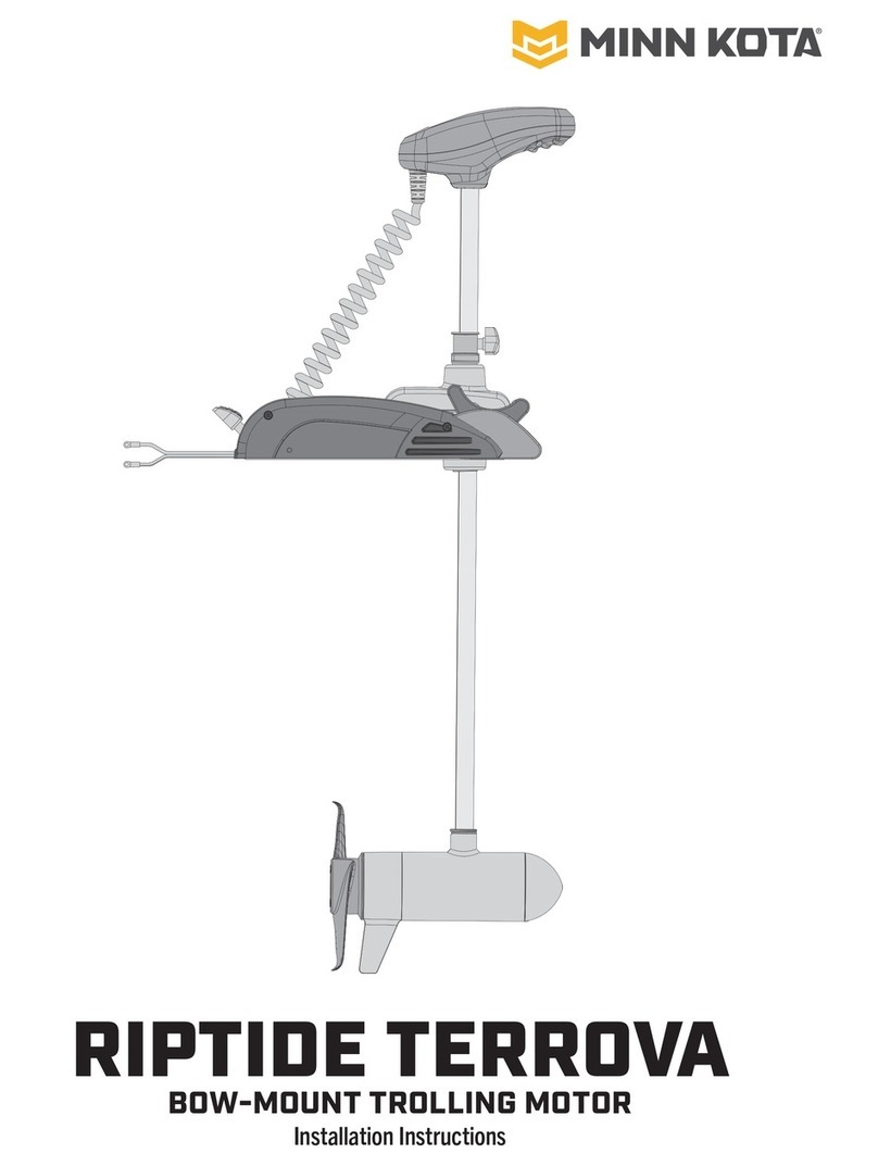
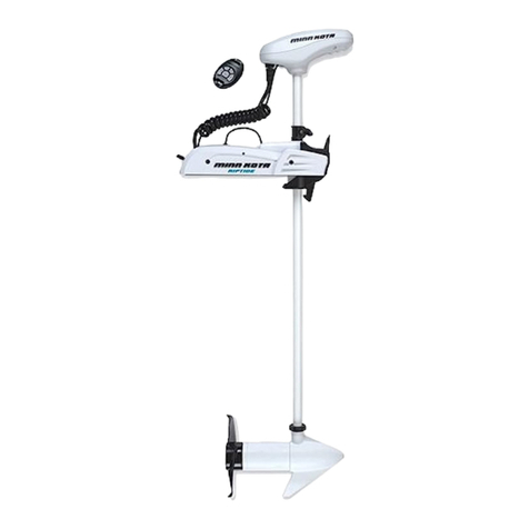
MINN KOTA RIPTIDE TERROVA User manual

MINN KOTA

MINN KOTA RIPTIDE TERROVA User manual

MINN KOTA EDGE 30 User manual

MINN KOTA

MINN KOTA EDGE 30 User manual

MINN KOTA RIPTIDE TERROVA User manual

MINN KOTA

MINN KOTA RIPTIDE TERROVA User manual

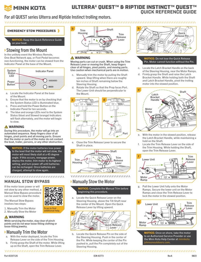
MINN KOTA ULTERRA QUEST User manual

MINN KOTA

MINN KOTA ULTERRA QUEST User manual

MINN KOTA MKA 32 QRB User manual

MINN KOTA

MINN KOTA MKA 32 QRB User manual

MINN KOTA RIPTIDE POWERDRIVE User manual

MINN KOTA

MINN KOTA RIPTIDE POWERDRIVE User manual

MINN KOTA EO 1/2 HP User manual

MINN KOTA

MINN KOTA EO 1/2 HP User manual

MINN KOTA RIPTIDE POWERDRIVE User manual

MINN KOTA

MINN KOTA RIPTIDE POWERDRIVE User manual

MINN KOTA RIPTIDE TERROVA User manual

MINN KOTA

MINN KOTA RIPTIDE TERROVA User manual

MINN KOTA FORTREX User manual

MINN KOTA

MINN KOTA FORTREX User manual

MINN KOTA MAXXUM Series User manual

MINN KOTA

MINN KOTA MAXXUM Series User manual

MINN KOTA Riptide 80 ST User manual

MINN KOTA

MINN KOTA Riptide 80 ST User manual

MINN KOTA VANTAGE User manual

MINN KOTA

MINN KOTA VANTAGE User manual

MINN KOTA ULTREX User manual

MINN KOTA

MINN KOTA ULTREX User manual

MINN KOTA ULTERRA User manual

MINN KOTA

MINN KOTA ULTERRA User manual

MINN KOTA RIPTIDE TERROVA 1363707 User manual

MINN KOTA

MINN KOTA RIPTIDE TERROVA 1363707 User manual

MINN KOTA ULTERRA User manual

MINN KOTA

MINN KOTA ULTERRA User manual

MINN KOTA TRAXXIS User manual

MINN KOTA

MINN KOTA TRAXXIS User manual

MINN KOTA Riptide Ulterra User manual

MINN KOTA

MINN KOTA Riptide Ulterra User manual

MINN KOTA TERROVA User manual

MINN KOTA

MINN KOTA TERROVA User manual

MINN KOTA RIPTIDE INSTINCT QUEST User manual

MINN KOTA

MINN KOTA RIPTIDE INSTINCT QUEST User manual

MINN KOTA Endura 50 User manual

MINN KOTA

MINN KOTA Endura 50 User manual

MINN KOTA 1810244 User manual

MINN KOTA

MINN KOTA 1810244 User manual

MINN KOTA ULTERRA Troubleshooting guide

MINN KOTA

MINN KOTA ULTERRA Troubleshooting guide

Popular Engine manuals by other brands

Baotian 139QMA Maintenance manual

Baotian

Baotian 139QMA Maintenance manual

Robin EC06 Service manual
Robin

Robin EC06 Service manual

Rockwell Automation MPL-B640 installation instructions

Rockwell Automation

Rockwell Automation MPL-B640 installation instructions

Bosch Rexroth A6VM series 71 manual

Bosch

Bosch Rexroth A6VM series 71 manual

Westerbeke 20B TWO Tehnical manual

Westerbeke

Westerbeke 20B TWO Tehnical manual

O.S. engine FS-52S Owner's instruction manual

O.S. engine

O.S. engine FS-52S Owner's instruction manual

NEUGART WPLE-B5 Mounting instructions

NEUGART

NEUGART WPLE-B5 Mounting instructions

Danfoss H1 Series technical information

Danfoss

Danfoss H1 Series technical information

Briggs & Stratton 405777 Series manual

Briggs & Stratton

Briggs & Stratton 405777 Series manual

Mercury 92-813054A2 manual

Mercury

Mercury 92-813054A2 manual

Foxtech REX340 user manual

Foxtech

Foxtech REX340 user manual

MerCruiser Vazer 100 user manual

MerCruiser

MerCruiser Vazer 100 user manual

Saito FG-60R3 instruction manual

Saito

Saito FG-60R3 instruction manual

Briggs & Stratton Vanguard 540000 Series Operator's manual

Briggs & Stratton

Briggs & Stratton Vanguard 540000 Series Operator's manual

REXROTH IndraDyn A Series Project planning manual

REXROTH

REXROTH IndraDyn A Series Project planning manual

Weston UK WEST EUROTECH 36 T2 instructions

Weston UK

Weston UK WEST EUROTECH 36 T2 instructions

Mitsubishi diesel engines Service manual

Mitsubishi

Mitsubishi diesel engines Service manual

Briggs & Stratton 400000 Professional Series Operator's manual

Briggs & Stratton

Briggs & Stratton 400000 Professional Series Operator's manual

manuals.online logo
manuals.online logoBrands
  • About & Mission
  • Contact us
  • Privacy Policy
  • Terms and Conditions

Copyright 2025 Manuals.Online. All Rights Reserved.