manuals.online logo
Brands
  1. Home
  2. •
  3. Brands
  4. •
  5. MINN KOTA
  6. •
  7. Outboard Motor
  8. •
  9. MINN KOTA Terrova 101 User manual

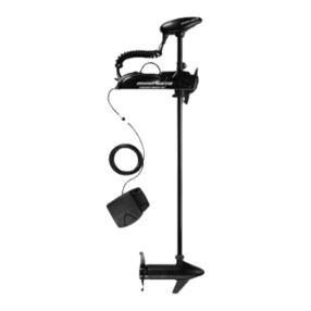
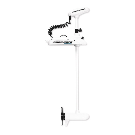
MINN KOTA Terrova 101 User manual

526
527
528
241
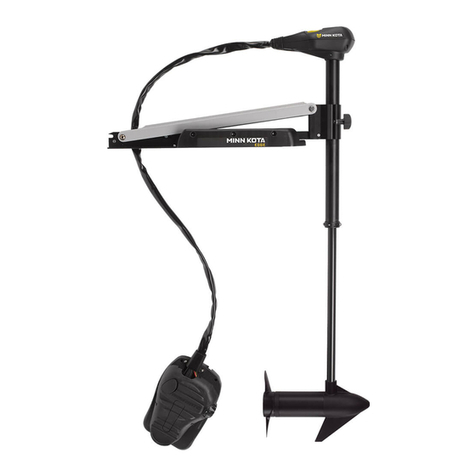
PARTS DIAGRAM
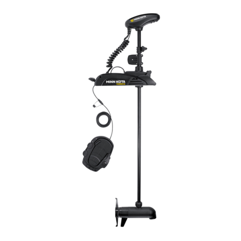
TERROVA 101
101 LBS THRUST
36 VOLT 46 AMPS
54” OR 60” SHAFT
850
for use with "N" serial numbers
2-year warranty
PARTS LIST
In the U.S.A., replacement parts may be ordered directly from MINN KOTA Parts Dept., 121 Power Drive,P.O. Box 8129 Mankato, Minnesota 56002-8129. In Canada, parts may be ordered from any of the
Canadian Authorized Service Centers shown on the enclosed list. Be sure to provide the model and serial numbers of your motor when ordering parts. Please use the correct part numbers from the parts
list. Payment for any parts ordered from the MINN KOTA parts department, may be by cash, personal check, Discover Card, MasterCard or VISA. To order, call 1-800-227-6433 or FAX 1-800-527-4464.
* This item is part of an assembly. This item cannot be sold separately due to machining and /or assembly that is required. P/N 2324932 REV. W ECN 34324 12/12
Fuera de los Estados Unidos, consultar la lista anexa para ubicar el Centro de servicio autorizado
MINN KOTA. No dejar de incluir el número del MODELO y el número de SERIE del motor para el cual
se solicitan las piezas. Usar siempre los números de pieza correctos indicados en la lista de piezas.
PARTS LIST
Item P/N Description Qty Item P/N Description Qty Item P/N Description Qty Item P/N Description Qty
1 2777052 36V Motor 60” FW 1
2777051 36V Motor 54” FW 1
2777054 36V Motor US2 60” 1
2777053 36V Motor US2 54” 1
5 2-100-216 Armature assembly 1
10 140-010 Bearing 1
15 788-040 Retaining ring 1
20 Included in #200 assemby
25 2-300-170 Brush end housing assembly 1
30 421-276 Plain end housing assembly STD 1
9421-286 Plain end housing US2 60” 1
9421-285 Plain end housing US2 54” 1
35 144-017 Flange bearing 1
40 880-025 Seal 2
50 188-094 Brush 2
60 2-600-199 Brush plate assembly 1
65 975-041 Brush spring 2
70 701-043 O-ring, motor 2
80 701-009 O-ring, thru-bolt 2
85 830-027 Screw, 10-32 x 2 2
90 830-096 Thru-bolt 2
830-098 Thru-bolt, Sonar only 2
95 990-051 Washer, steel 2
100 990-052 Washer, nylatron 2
110 973-025 Spacer, brush plate 2
115 992-010 Washer, Belleville 2
120 990-045 Spacer, thrust 1
125 582-014 Clip, retaining, long 1
135 640-025 Leadwire, black 1
136 640-133 Leadwire, red 1
137 640-317 Groundwire, brown, US2 only 1
200 2777115 Tube, composite 60” FW 1
205 Included in #200 assemby
210 2325665 Decal, cover 2
215 2325678 Decal, ctrl box 101 1
2325679 Decal, ctrl box 101 US2 1
2325680 Decal, ctrl box 101 Autopilot 1
2325681 Decal, ctrl box 101 Autopilot & US2 1
220 2320200 Cover, ctrl box 1
225 2324030 Ctrl board, compass, Autpillot only 1
230 2302960 Grommet, compass, Autopilot only 3
235 2065400 Wire insulator 2
240 2218200 Fuse holder, US2 only 1
241 2375400 Shrink Tube 1/4” OD x 1 3/4” 2
245 2372100 Screw, 8-18 x .625 3
250 2052510 Cable clamp 3
255 2322500 Ctrl box 1
260 2332102 Screw, 10-24 1
265 2372100 Screw, 8-18 x .625 4
270 2333101 Nut, 10-24 1
275 2224700 Plug, ctrl box, US2 motors only 1
2224702 Plug, ctrl box 1
300 2211415 Universal sonar 2 extension cable 1
305 2771500 Depth collar assembly 1
315 2260906 Knob (included in #305) 1
320 2321706 Washer (included in #305) 1
321 2323102 Nut (included in #305) 1
325 2997025 Steering housing 1
330 2326501 Steering housing top 1
335 2324604 O-ring, case seal 1
345 2302605 Roll pin 5/16 4
350 2308601 Breather, filter 1
355 2328610 Cradle, motor 1
370 2777025 Motor, steering assembly 1
380 2302255 Gear, cluster 3rd stage 1
385 2302250 Gear, cluster 2nd stage 1
390 2302245 Gear, cluster 1st stage 1
395 2302610 Shaft, gear 1st stage 1
400 2302620 Shaft, gear 3rd stage 1
405 2302615 Shaft, gear 2nd stage 1
410 2321704 Washer, thrust 2
415 2321515 Liner, output tube 1
420 2324608 O-ring, 224 2
425 2321720 Shim, O-ring 2
430 2327308 Bearing, ball sealed 2
435 2322200 Gear, output 1
440 2324601 O-ring, output gear 1
445 2322030 Tube, output machined 1
450 2321510 Collar, drive, bottom 1
455 2326506 Steering housing, Bottom 1
465 2322600 Pin, latch, zp 1
470 2322602 Pin, pivot, zp 1
475 2327310 Bushing, pivot pin 2
480 2321702 Washer, flat .375 2
485 2263011 E-ring .375 2
490 2322702 Spring, latch pin 2
495 2323410 Screw, 8-32 x .75 1
500 2323408 Screw, 8-32 x 2 7
510 2090651 Leawire, 10 ga 1
525 2991271 Coil cord, 54” / 60” 1
2991272 Coil cord, US2, 54” / 60” 1
526 2325401 Shrink Tube 3/4” ID x 2” w/adhs 1
527 2307313 Bead-Ferrite 1
528 2320710 Terminal-Amp (T-Tab) 1
530 2320202 Cap, dust, coil cord, non-AP only 1
535 2325641 Decal, sideplate, left 1
540 2323404 Screw, 1/4-20 4
545 2321915 Sideplate, left 1
550 2323403 Screw, 1/4-20 x .375 2
555 2321925 Skid, left 1
560 2323422 Screw, 10-24 x .375 2
565 2321700 Washer, #10 SS 2
570 2323500 Bolt, shoulder 2
575 2323905 Ramp, 4” left 1
580 2325115 Pad, rubber rest 4
585 2321706 Washer, #8 4
590 2323412 Screw, 8-18 x .25 4
595 2324705 Insert, ramp 2
600 2994202 Arm, release, left 1
605 2322710 Spring, extension 2
n  2770250 Cover, speed control with decal 1
620 2325650 Decal, speed control 1
625 2320210 Cover, speed control 1
630 2322901 Strain relief 1
635 2324017 Control board, 24-36v 1
n  2884050 Switch-reed repair kit
636 2320208 Dust plug 1
640 2320203 Cap, dust, control board 1
645 2323406 Screw, 10-24 x 2
650 2321315 Holder, connector 1
655 2332103 Screw, 6-20 x .375 2
660 2074072 Battery meter, 36v 1
665 2323402 Screw, 1/4-20 x .375 4
670 2321940 Bracket, strain relief 1
675 2321310 Strain relief, wire 1
680 2323405 Screw, 1/4-20 x .5 1
685 2013100 Speed nut, .375 2
690 2320215 Handle, release cover 1
695 2301700 Bushing, 1
700 2322701 Spring, release handle 1
710 2320400 Handle, release FW 1
715 2322712 Spring, release handle 2
720 2322604 Bushing, handle 2
725 2332104 Screw, 1/4-20 x .625 2
730 2323000 E-clip, 3/16, SS 2
735 2322606 Pin, follower, handle 1
740 2321901 Base extrusion, machined 1
745 2322912 Spring pin, 2
750 2321950 Bracket, sideplate 1
755 2323900 Ramp, 4” right 1
757 2994204 Arm, release, Right 1
760 2321920 Skid, right 1
765 2301310 Screw, 8-18 x .5 3
770 2320220 Cover, access, FW 1
775 2321910 Sideplate, right 1
780 2325640 Decal, sideplate, right 1
850 2994720 Foot pedal 1
851 2326710 Plug, foot pedal 1
860 2324400 Pedal, heel-toe 1
865 2322714 Spring, momentary 1
870 2321300 Clamp 2
875 2223430 Screw, 8 x .75 4
880 2328600 Flex finger 1
885 2323710 Button, momentary, left 1
900 2325660 Decal, foot pedal 1
910 2320205 Cover, heel-toe 1
915 2323725 Button, AP 1
920 2323715 Button, Mom/Con 1
925 2320100 Knob, speed, foot pedal 1
930 2332103 Screw, 6-20 x .375 2
935 2324020 Control board, foot pedal 1
936 2320207 Dust cap 1
940 2322900 Strain relief, foot pedal 1
945 2324500 Base plate, foot pedal 1
950 2301310 Screw, #8 x .5 10
955 2323700 Button, steer, left 1
960 2323705 Button, momentary 1
965 2323701 Button, steer, right 1
970 2322704 Spring, foot pedal 5
975 2994859 Bumper, bag assy 1
980 2322706 Spring, barrel 2
985 2323420 Screw, 8-18 x .375 2
990 2372100 Screw, 8-18 x .625 2
n  1378132 Propeller kit WW2
n  2994876 Propeller bag assy
1000 2331160 Propeller WW2 1
1010 2262658 Drive pin, large 1
1015 2091701 Washer, prop, large 1
1020 2093101 Nut, nylock, prop, large 1
n  2994864 Mounting hardware bag assy
n  2889460 Seal & Oring Kit
2. PUSH
DOWN
OPERATION FONCTIONNEMENT
5
GÉNÉRALE:
Système prêt (vert) : Le moteur est équipé d’un voyant indiquant que le système est prêt. Le voyant est allumé quand le moteur
est déployé et sous tension. Quand le moteur est correctement rangé, le voyant s’éteint indiquant ainsi que le courant au
moteur a été coupé. Si le voyant ne s’allume pas quand le moteur est déployé, assurez-vous que le moteur est bien connecté
à la batterie et complètement déployé. Si le voyant ne s’éteint pas quand le moteur est rangé, assurez-vous que le levier de
rangement/déploiement est complètement enclenché et verrouillé en position rangé.
ARRIMAGE:
Enfoncez et tenez le levier de rangement/déploiement vers le bas. Inclinez gentiment et tirez l’arbre de composite ou la tête de
commande jusqu’à ce que le moteur entre sur les rampes. Le moteur devrait reposer sur les rampes et se bloquer en place. Le
levier de rangement/déploiement devrait s’enclencher automatiquement en position rangée. Le voyant (vert) indiquant que le
système est prêt DOIT s’éteindre indiquant ainsi que le moteur est correctement rangé.
DÉPLOIEMENT:
Enfoncez et tournez le levier de rangement/déploiement vers le bas. Glissez gentiment le moteur hors des rampes. Abaissez le
moteur à la profondeur désirée en vous assurant qu’il s’enclenche dans une position verticale sûre. Le voyant (vert) indiquant
que le système est prêt à fonctionner sera allumé.
TRANSPORT:
Dans le cas où le moteur est soumis à des vibrations ou à des chocs violents, veiller à assurer un arrimage ferme. Mettre le collier
de profondeur contre le moteur de direction et le serrer.
ATTENTION: LORS DE LA DESCENTE OU DU REL-
EVAGE DU MOTEUR, NE PAS APPROCHER LES
DOIGTS DES PIVOTS ET DES PIÈCES MOBILES.
GENERAL:
System Ready (green): The motor is equipped with a system ready indicator. Indicator light will be on when motor is deployed
and power is applied to the motor. When the motor is properly stowed the indicator light will go off indicating all power has been
turned off to the motor. If this indicator light does not come on when deployed, check that motor is connected to battery properly
and motor is completely deployed. If indicator light does not go off when stowed, be sure that stow/deploy lever is fully latched
and locked into the stowed position.
TO STOW:
Push and hold the stow/deploy lever down. Gently tilt and pull the composite shaft or control head until the motor engages the
motor ramps. Motor should rest on the motor ramps and lock into place. The stow/deploy lever should latch automatically into
the stowed position. System ready indicator light (green) MUST go off for the motor to be stowed properly.
TO DEPLOY:
Push in and rotate the stow/deploy lever down. Gently slide the motor out from the ramps. Lower the motor to the desired depth mak-
ing sure it clicks into a secure, vertical position. System ready indicator light (green) will be lit indicating motor is ready for operation.
TRANSPORTATION:
In conditions where the stowed motor is subject to high levels of shock or vibration, take care to provide a secure stow. Move the
depth collar snug against the steering motor and tighten.
WARNING : WHEN RAISING OR LOWERING MOTOR,
KEEP FINGERS CLEAR OF ALL HINGE AND PIVOT
POINTS AND ALL MOVING PARTS.
Fall away motor ramps
Rampes de moteur escamotables
Tilt Lock Lever Operation
Le levier Opérationde ver-
rouillage d’inclinaison
System Ready Indicator
Système Prêt lumière
WIRING DIAGRAM SCHÉMA DE CÂBLAGE
12
1. PUSH IN
RED/ROUGE M+
BLACK/NOIR M-
CONTROL BOARD/
CARTE DE COMMANDE
RED/ROUGE
WHITE/BLANC
FOOT PEDAL
CONTROL BOARD/
CARTE DE COMMANDE
DE LA PƒDALE
STEERING MOTOR/
MOTEUR DE DIRECTION
BATTERY GAUGE/
VOLTMéTRE
BATTERY 1
BATTERIE 1
BATTERY 2
BATTERIE 2
BLACK/NOIR B-
RED/ROUGE B+
COIL CORD/
CORDONE
MOTOR/
MOTEUR
RED/ROUGE M+
BLACK/NOIR M-
UNIVERSAL SONAR 2 WIRE *
SONAR UNIVERSEL 2 FIL *
BLACK/NOIR
UNIVERSAL SONAR 2 EXTENSION WIRE *
SONAR UNIVERSEL 2 FIL D’EXTENSION *
COMPASS/
BOUSSOLE
SENSOR
BOARD/
CARTE DE
CAPTEUR
BROWN *
MARRON *
BROWN/MARRON
BATTERY 1
BATTERIE 1
BATTERY 1
BATTERIE 1
BATTERY 2
BATTERIE 2 BATTERY 3
BATTERIE 3
BLACK/NOIR
AUTOPILOT INDICATOR, RED
L’AUTOPILOT
LUMIÈRE, ROUGE
SYSTEM READY INDICATOR, GREEN
SYSTÈME PRÊT LUMIÈRE, VERT
REED SWITCH
INTERRUPTEUR À ANCHE
AUTO PILOT INDICATOR, RED
(EQUIPPED MOTORS ONLY)
L’AUTOPILOT
LUMIÈRE, ROUGE
(MOTEURS ÉQUIPÉS SEULEMENT)
MOMENTARY / CONSTANT
INDICATOR, GREEN
MOMENTANÉ / CONTINU
LUMIÈRE, VERT
ACCESSORY PLUG
PRISE D’ACCESSOIRE
SPEED ADJUSTMENT KNOB
MOLETTE DE REGLAGE DE
LA VITESSE
AUTOPILOT ON EQUIPPED MOTORS ONLY
PILOTE AUTOMATIQUE SEULEMENT SUR
MOTEURS ÉQUIPÉS
ACCESSORY PLUG
PRISE D’ACCESSOIRE
ACCESSORY PLUG
PRISE D’ACCESSOIRE
B+
M+
B-
M-
12v
24v
36v
*US MOTORS ONLY
*MOTEURS US SEULEMENT
FUSE *
FUSIBLE *
THIS IS A UNIVERSAL MULTI-VOLTAGE DIAGRAM. DOUBLE CHECK YOUR MOTORS VOLTAGE FOR PROPER CONNECTIONS.
Wiring diagram for board p/n 2324017 (see next page for 2324019)
Terrova 101 is 36-volt only!
WIRING DIAGRAM
10
PROPELLER MOTOR MAINTENANCE MOTOR
TROUBLESHOOTING
11
PROPELLER REPLACEMENT:
• Disconnect motor from battery prior to changing the
propeller.
• Hold the propeller and loosen the prop nut with a pliers
or a wrench.
• Remove prop nut and washer. If the drive pin is sheared/
broken, you will need to hold the shaft steady with a
screwdriver blade pressed into the slot on the end of the
shaft.
• Turn the old prop to horizontal ( as illustrated ) and pull it
straight off. If drive pin falls out, push it back in.
• Align new propeller with drive pin.
• Install prop washer and prop nut.
• Tighten prop nut 1/4 turn past snug. [25-35 inch lbs.] Be
careful, over tightening can damage prop.
CAUTION: DISCONNECT THE MOTOR
FROM THE BATTERY BEFORE BEGINNING
ANY PROP WORK OR MAINTENANCE.
MOTOR MAINTENANCE:
1. After use in salt or brackish water these units should be rinsed with fresh water, then wiped down with a cloth dampened
with an aqueous based silicone spray such as Armor All®.
2. The propeller must be cleaned of weeds and fishing line. The line can get behind the prop, wear away the seals and allow
water to enter the motor. Disconnect battery and check this after every 20 hours of operation.
3. To prevent accidental damage during trailering or storage, disconnect the battery whenever the motor is off of the water. For
prolonged storage, lightly coat all metal parts with silicone spray.
4. For maximum performance, restore battery to full charge before each use. Unless you are using a power panel or MINNKOTA
battery charger, disconnect the trolling motor when charging the battery.
5. The composite shaft requires periodic cleaning and
lubrication for proper retraction and deployment. A coating of Armor All® will provide “like new” operation.
6. The weedless wedge propeller is designed to provide absolute weed free operation with very high efficiency. To maintain top
performance, the leading edge of the blades must be kept smooth. If this edge is rough or nicked, restore to smooth by sand-
ing with fine sandpaper.
MOTOR TROUBLESHOOTING:
1. Motor fails to run or lacks power:
• Check battery connections for proper polarity.
• Make sure terminals are clean and corrosion free.
• Check battery water level. Add water if needed.
2. Motor loses power after a short running time:
• Check battery/batteries charge, if low, restore to full charge.
3. Motor is hard to steer.
• Make sure the drive/depth collar is tight and fully engaged with the drive motor.
• Lubricate the composite shaft.
4. Motor does not respond to foot pedal commands.
• Make sure the cable connector plugs at the drive
mount are secure.
5. Control head vibrates during normal operation:
• Remove and rotate the prop 180°. See removal instructions in prop section.
NOTE: For all other malfunctions, see enclosed authorized service center listing for nearest service center.
NOTICE: DO NOT APPLY LUBRICANT OR ANY TYPE OF GREASE TO TROLLING MOTOR CONNECTORS
WEEDLESS
PROPELLER
DRIVE PIN
ANODE / NUT
WASHER
SLOT
B+
M+
B-
M-
12v
24v
36v
RED M+
BLACK M-
RED
WHITE
FOOT PEDAL
CONTROL BOARD
STEERING MOTOR
BATTERY GAUGE
BATTERY 1 BATTERY 2
BLACK B-
RED B+
COIL CORD
MOTOR
RED M+
BLACK M-
BLACK
COMPASS
SENSOR
BOARD
BATTERY 1
BATTERY 1 BATTERY 2
BATTERY 3
BLACK
AUTOPILOT INDICATOR, RED
SYSTEM READY INDICATOR, GREEN
REED SWITCH
AUTO PILOT INDICATOR, RED
(EQUIPPED MOTORS ONLY)
MOMENTARY / CONSTANT
INDICATOR, GREEN
ACCESSORY PLUG
SPEED ADJUSTMENT KNOB
AUTOPILOT ON EQUIPPED MOTORS ONLY
ACCESSORY PLUG
ACCESSORY PLUG
THIS IS A UNIVERSAL MULTI-VOLTAGE DIAGRAM. DOUBLE CHECK YOUR MOTORS VOLTAGE FOR PROPER CONNECTIONS
CONTROL BOARD/
CARTE DE COMMANDE
Terrova 101 is 36-volt only!
Wiring diagram for board p/n 2324019 (see prior page for 2324017)

Other MINN KOTA Outboard Motor manuals

MINN KOTA RIPTIDE POWERDRIVE User manual

MINN KOTA

MINN KOTA RIPTIDE POWERDRIVE User manual

MINN KOTA TALON User manual

MINN KOTA

MINN KOTA TALON User manual

MINN KOTA ULTREX User manual

MINN KOTA

MINN KOTA ULTREX User manual

MINN KOTA ULTERRA User manual

MINN KOTA

MINN KOTA ULTERRA User manual

MINN KOTA Ultrex 1368800 User manual

MINN KOTA

MINN KOTA Ultrex 1368800 User manual

MINN KOTA ULTERRA User manual

MINN KOTA

MINN KOTA ULTERRA User manual

MINN KOTA POWERDRIVE 42 User manual

MINN KOTA

MINN KOTA POWERDRIVE 42 User manual

MINN KOTA ULTERRA User manual

MINN KOTA

MINN KOTA ULTERRA User manual

MINN KOTA Riptide Ulterra User manual

MINN KOTA

MINN KOTA Riptide Ulterra User manual

MINN KOTA Riptide User manual

MINN KOTA

MINN KOTA Riptide User manual

MINN KOTA EDGE User manual

MINN KOTA

MINN KOTA EDGE User manual

MINN KOTA RIPTIDE MAXXUM User manual

MINN KOTA

MINN KOTA RIPTIDE MAXXUM User manual

MINN KOTA TERROVA User manual

MINN KOTA

MINN KOTA TERROVA User manual

MINN KOTA FORTEX User manual

MINN KOTA

MINN KOTA FORTEX User manual

MINN KOTA MAXXUM User manual

MINN KOTA

MINN KOTA MAXXUM User manual

MINN KOTA MAXXUM User manual

MINN KOTA

MINN KOTA MAXXUM User manual

MINN KOTA ULTERRA i-Pilot User manual

MINN KOTA

MINN KOTA ULTERRA i-Pilot User manual

MINN KOTA RIPTIDE TERROVA User manual

MINN KOTA

MINN KOTA RIPTIDE TERROVA User manual

MINN KOTA ULTREX User manual

MINN KOTA

MINN KOTA ULTREX User manual

MINN KOTA FORTREX User manual

MINN KOTA

MINN KOTA FORTREX User manual

MINN KOTA Endura C2 50 User manual

MINN KOTA

MINN KOTA Endura C2 50 User manual

MINN KOTA CoPilot User manual

MINN KOTA

MINN KOTA CoPilot User manual

MINN KOTA CAMO 45 User manual

MINN KOTA

MINN KOTA CAMO 45 User manual

MINN KOTA RIPTIDE SE User manual

MINN KOTA

MINN KOTA RIPTIDE SE User manual

Popular Outboard Motor manuals by other brands

Carp Design X Series Usual manual

Carp Design

Carp Design X Series Usual manual

Side-Power SR(P) 80/185 T Installation & user guide

Side-Power

Side-Power SR(P) 80/185 T Installation & user guide

Mercury 75 Service manual

Mercury

Mercury 75 Service manual

Mercury motorguide X5-55 Operation, maintenance & installation manual

Mercury

Mercury motorguide X5-55 Operation, maintenance & installation manual

BRP Evinrude E-TEC Series installation manual

BRP

BRP Evinrude E-TEC Series installation manual

Sleipner SE25 installation guide

Sleipner

Sleipner SE25 installation guide

Side-Power SE 60/185 S Installation and user manual

Side-Power

Side-Power SE 60/185 S Installation and user manual

HASWING Cayman B GPS Series owner's manual

HASWING

HASWING Cayman B GPS Series owner's manual

Sleipner ERV250/300TC-48V installation guide

Sleipner

Sleipner ERV250/300TC-48V installation guide

SLEIPNER MOTOR AS SE 30 S IP Installation and user manual

SLEIPNER MOTOR AS

SLEIPNER MOTOR AS SE 30 S IP Installation and user manual

Vetus Bow Thruster BOW PRO A Series installation instructions

Vetus

Vetus Bow Thruster BOW PRO A Series installation instructions

Sleipner E-Vision E100 installation guide

Sleipner

Sleipner E-Vision E100 installation guide

TOHATSU M 40D2 owner's manual

TOHATSU

TOHATSU M 40D2 owner's manual

Volvo Penta Aquamatic 250C Workshop manual

Volvo Penta

Volvo Penta Aquamatic 250C Workshop manual

Yamaha 115C owner's manual

Yamaha

Yamaha 115C owner's manual

RHINO BLX 65 BMR owner's manual

RHINO

RHINO BLX 65 BMR owner's manual

Yamaha 115 owner's manual

Yamaha

Yamaha 115 owner's manual

IMCO Xtreme Advantage scX4 Service manual

IMCO

IMCO Xtreme Advantage scX4 Service manual

manuals.online logo
manuals.online logoBrands
  • About & Mission
  • Contact us
  • Privacy Policy
  • Terms and Conditions

Copyright 2025 Manuals.Online. All Rights Reserved.