Minuit Une IVL Square User manual

SERVICE MANUAL
IVL™Square


IVL™Square Service Manual Rev A0 i
Edition Notes
© 2019 ARTEFFECT SAS
All rights reserved. Information subject to change without notice. ARTEFFECT and all affiliated companies disclaim
liability for any injury, damage, direct or indirect loss, consequential or economic loss or any other loss occasioned
by the use of, inability to use or reliance on the information contained in this document. Minuit Une, IVL LIGHTING,
IVL Square are registered trademarks of ARTEFFECT SAS (hereinafter referred to as “Minuit Une”).
No part of this document may be used for distribution, reproduction, transmission, transcription, storage in a data
retrieval system, or translated into any language in any form by any means without the prior written permission of
ARTEFFECT. If you are downloading files from our web pages for your personal use, make sure to check for updated
versions. ARTEFFECT cannot take any liability whatsoever for downloaded files, as technical data are subject to
change without notice.
This document uses non-contractuel photos
www.minuitune.com | 104 avenue de la résistance 93100 Montreuil –FRANCE | + 33 (0)1 48 97 43 82
support@minuitune.com
Revision of this manual: A0

ii IVL™ Square Service Manual Rev A0
Table of Content
Edition Notes ..............................................................................................................................i
Table of Content.........................................................................................................................ii
Important Information ...............................................................................................................1
Risk Levels and Alert Symbols ............................................................................................................. 1
Vital Precautions and general safety information ................................................................................ 2
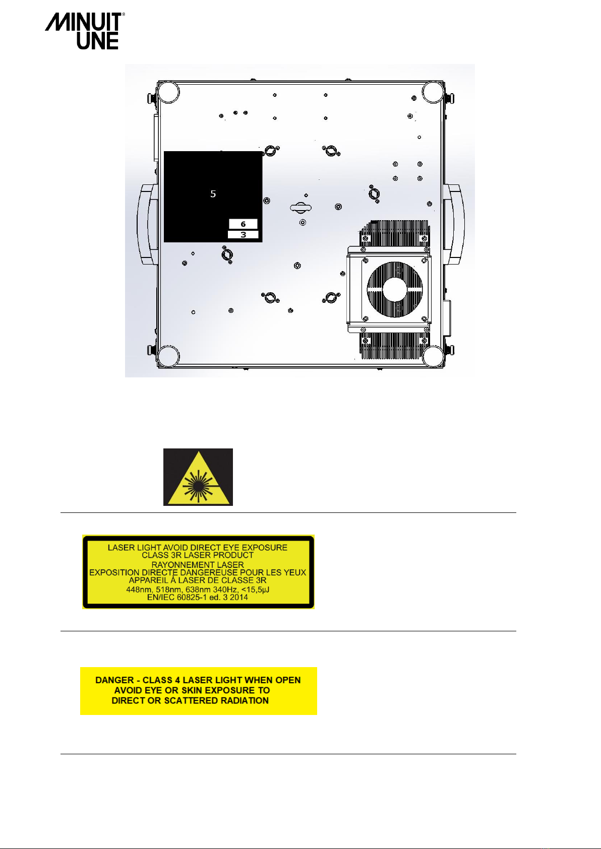
Important Laser Information............................................................................................................... 3
Labelling diagram ............................................................................................................................... 3
OVERVIEW .................................................................................................................................6
IVL Square and Base Dimensions ......................................................................................................... 6
IVL Pyramid Dimensions *................................................................................................................... 7
Fixture menu and connectors.............................................................................................................. 8
Menu buttons ..................................................................................................................................................... 8
Display and LED indicators .................................................................................................................................. 8
Tools and accessories.......................................................................................................................... 9
Tools ................................................................................................................................................................... 9
Free ESD kit –Antistatic mat ............................................................................................................................... 9
Service accessories.............................................................................................................................................. 9
Spare part view ................................................................................................................................ 10
Lower Part .........................................................................................................................................................10
Lower Spare Part list ..........................................................................................................................................11
Upper part .........................................................................................................................................................12
TROUBLESHOOTING .................................................................................................................13
Table of potential issues observed on operational product* .............................................................. 13
SERVICE OPERATION ................................................................................................................15
Removing the Square Plexiglas shape................................................................................................ 15
Square to Pyramid Plexiglas shape service procedure ........................................................................ 16
Set Up Plate Service Procedure ......................................................................................................... 17
Opening the IVL ................................................................................................................................ 18
Removing the Upper Part (1/2) ..........................................................................................................................18
Removing the Upper Part (2/2) ..........................................................................................................................19
A. General parts.......................................................................................................................... 20
Check Power Supply (PSU) .................................................................................................................................20
Replacing Power Supply.....................................................................................................................................20
Replacing Fans ...................................................................................................................................................22
Replacing Mainboard .........................................................................................................................................24
Mainboard wiring ..............................................................................................................................................24
Remove the Mainboard .....................................................................................................................................25

IVL™Square Service Manual Rev A0 iii
B. Central Parts........................................................................................................................... 26
Replacing the Scanning Motor ...........................................................................................................................26
Replacing Scanning Mirror Board .......................................................................................................................27
Scanning Mirror Board wiring ............................................................................................................................27
Replacing Scanning Mirror Sensor......................................................................................................................28
Start Scanning Mirror without AC Power / DMX ................................................................................................29
Check / Invert the rotation way .........................................................................................................................30
Check the Scanning Mirror sensor signal with an oscilloscope ...........................................................................31
Set the Scanning Mirror sensor signal with an oscilloscope................................................................................32
Set the Scanning Mirror sensor signal without an oscilloscope ..........................................................................32
C. Tilt Mirror Parts ......................................................................................................................... 33
Motor-Mirror coupling.......................................................................................................................................33
Zero Sensor ........................................................................................................................................................33
Zero Sensor –Tilt Detector setting procedure....................................................................................................34
Replacing the Stepper Motor (A)........................................................................................................................35
Replacing the TILT Mirror (B) .............................................................................................................................37
Stepper Motor Board Pinout..............................................................................................................................38
Replacing Stepper Motor Board .........................................................................................................................38
Stepper Motor Board addressing ID ...................................................................................................................39
CLEANING ............................................................................................. Erreur ! Signet non défini.
Scanning Mirror cleaning .................................................................................................................. 40
Inside mirror cleaning ....................................................................................................................... 41
Fans cleaning.................................................................................................................................... 41
Square Plexiglass Shape and Tilt Mirrors cleaning .............................................................................. 43
To clean the Square Plexiglass Shape: ................................................................................................................43
To clean the Tilt Mirrors and the Metallic housing parts ....................................................................................43
Service Return Form .................................................................................................................44


IVL™Square Service Manual Rev A0 1
Important Information
This service Manual contains instruction about how to service Minuit Une’s IVL Square product.
Service work must comply with local regulations and accepted codes of good practice.
Any person in charge of servicing this product shall have receive a service training by Minuit Une and/or
by an official training center recognized by Minuit Une.
Read and understood all safety information and procedure in this service manual, and in the IVL
Square’s user manual before servicing or cleaning this product.
Failure to respect service procedure may cause damage that is not covered by product warranties.
Any procedure or work on the product which is not described in this manual is not covered by product
warranties.
Always turn off and disconnect the product from power before removing the plexiglas shape or opening
the product, or performing procedures of service
Risk Levels and Alert Symbols
Safety warnings, safety alert symbols, and signal words in these instructions indicate different risk levels:
DANGER indicates an imminent hazardous situation which, if not avoided, will result in death or
serious injury.
WARNING indicates a potentially hazardous situation which, if not avoided, may result in death or
serious injury.
CAUTION indicates an potentially hazardous situation which, if not avoided, may result in minor or
moderate injury.
NOTICE explains practices not related to physical injury. No safety alert symbol appears with this
signal word.

2 IVL™ Square Service Manual Rev A0
Vital Precautions and general safety information
Humidity, Condensation and Moisture.
Never expose the product to rain or moisture.
Do not use this apparatus near water.
Clean only with a dry cloth.
Never expose the product to dripping water or water splashes.
Never place an object filled with liquid (e.g. a vase or a bottle filled with liquid) on the product.
Risk of injury and damage through falls.
Always service the product on a stable platform.
Never hang the product before doing service on it.
Risk of electric shock and fire.
Disconnect the product from AC power before doing service on it.
Do not service near any heat sources such as radiators, heat registers, stoves, or other apparatus
(including amplifiers) that produce heat.
No flame source, like a candlelight, should be placed on or nearby the product.
Wait until the product is at room temperature before handling.
Class 3R laser product according to IEC 60825-1:2014
Avoid direct eye exposure.
Do not look at laser devices with magnifiers, telescopes, binoculars or similar optical instruments
that may concentrate the light output.
Please refer to ANSI Z136.1 “Standard for Safe Use of Lasers” for guidance on safe
use. This publication is available from Laser Institute of America
Note that the national and local recommendations, regulations, standards and codes of practice in
laser show are different from a country to another.
Please contact your provider or Minuit Une’s legal service if you have any interrogation.
High voltage! Risk of blindness, electric shock and fire.
Read and understand all safety information and operation instructions before you service the product.
Not observing the safety information or general rules of safety may cause injury, blindness, burn
hazards, electric shock, falls and death to yourself and others or damage to equipment.
Use solely and exclusively as described in the instructions.
Using the product in any other ways than described in this manual is not permitted and can damage
the product and lead to associated risks such as short-circuit, fire, electric shock, etc.
Use of controls or adjustments or performance of procedures other than those specified herein may
result in hazardous radiation exposure.
Do not bypass or remove any safety feature of the product.
Only use the attachments/ accessories specified by the manufacturer
Always work in a clean, well-lit area.
Always take the necessary precaution to prevent static electricity from damaging the product during
service.
Regular cleaning is very important for fixture life and performance.

IVL™Square Service Manual Rev A0 3
Important Laser Information
Procedures that could allow access to Class 4 levels of radiation include the following:
•Removing the square Plexiglas shape (page 15)
•Square to pyramid Plexiglas shape (page 16)
•Opening the IVL (page 18/19)
•All the procedure which can be done with the IVL open
To avoid increase accessible emission level of radiation during the procedure listed above, you should always
turn off and disconnect the product from power before removing the plexiglas shape or opening the product
This will be regularly recall in this manual with the following label:
Labelling diagram
The following symbols are used in this manual or on the product to identify important safety
information:

4 IVL™ Square Service Manual Rev A0
1. Hazard Warning Symbol Label
Warning! Visible and / or invisible Laser Radiation
can be emitted.
2. Explanatory label
This Laser product is designated as Class
3R during all procedures of operation
Laser parameters:
Wavelength: 448nm, 518nm, 638nm
Emission type: pulsed (340Hz)
Energy: <15,5uJ
3. Protective Housing Non-interlocked Label
Before opening any part of the product,
disconnect the AC power. Otherwise you
may be exposed to a class 4 Laser.
MINUIT UNE cannot be held responsible
if this instruction is not respected
This label is also present on the embed
laser inside the product (see figure 8)

IVL™Square Service Manual Rev A0 5
5. Manufacturer’s Identification Label
The manufacturer plate is located at
the bottom of the product. It contains
important information about the
type, serial number, and safety.
Please contact your dealer or Minuit
Une when a type plate is missing as it
must be present on the product and
needs to be replaced.
6. Certification Label
7. Power Label
4. Aperture Label
This label indicates the laser aperture. On this
product, the laser aperture is the whole area
above the Plexiglas shape of the product.

6 IVL™ Square Service Manual Rev A0
OVERVIEW
All dimensions are given in millimetres.
IVL Square and Base Dimensions
FIGURE 1:IVL SQUARE DIMENSIONS

IVL™Square Service Manual Rev A0 7
IVL Pyramid Dimensions *
*The Pyramid is a service accessory described in section “Square to Pyramid Plexiglas shape service procedure”, page 17.
FIGURE 2:IVL PYRAMID DIMENSIONS

8 IVL™ Square Service Manual Rev A0
Fixture menu and connectors
FIGURE 3:FRONT PANEL DESCRIPTIONS
Menu buttons
Display and LED indicators
The display shows fixture and menu information.
The Green LED is the DMX connector / interlock
indicator: it lights up when a valid DMX signal is
detected at the DMX Input.
The Red LED is the safety signal indicator: it lights up
when the safety signal is “passed”.
If you push the Minus button, the display shows the sub-
menu information like the software version, the maximal
temperature, and the lifetime of the IVL.
ENTER
Press to open the main menu.
Press to open a sub menu.
ESC
Cancel an action without saving any changes.
+ / -
-
-
Select an option or change a value.
Push to display the software version, the maximal temperature, and the lifetime of the IVL.
Hold for 5 seconds to display the four first DMX frameworks received in real-time by the product.
Menu Buttons
safety Indicator (red
light)
Display
DMX Indicator
(green)
Connector Panel and
Mains Switch
FIGURE 4:MAIN MENU
FIGURE 5:SUB MENU

IVL™Square Service Manual Rev A0 9
Tools and accessories
Here are the different tools and accessories necessary to do service on the product.
All these tools and accessories are not provided with the product.
Tools
1. Wrench key T7
2. Cruciform (Phillips) screwdriver PH1/PH2
3. Hexagonal screwdriver T3
4. Removable bit / Torx screwdriver T3
5. Thin rod hexagonal screwdriver
6. Small and long Allen key T2
7. Small and long Allen key T3
8. Loctite 243 thread lock
9. Thin-nosed flat pliers
10. Thin-nosed cutting pliers
11. Brussels Precision tweezers
Free ESD kit –Antistatic mat
1. Connect the mat to an earthing contact.
2. Connect yourself to the mat by the strap (the green
cable on the picture beside).
Service accessories
Description
Order Reference
Section
Pyramid Plexiglas Shape
ACCE-00009
Service Operation, p.17
Set Up Plate Accessory
ACCE-00013
Service Operation, p.18
FIGURE 6:TOOLS
FIGURE 7:FREE ESD KIT

10 IVL™ Square Service Manual Rev A0
Spare part view
Lower Part
1
2
4
6
7
8
9
10
11a
12
25
26
27
28
29
5
5b
34
31
33
FIGURE 8:SPARE PART –INSIDE VIEW
FIGURE 9:SPARE PART –BOTTOM VIEW
11b
EMBED
LASER
Protective Housing
Non-interlocked Label

IVL™Square Service Manual Rev A0 11
Lower Spare Part list
Spare part
number
Description
Reference
Section
1
Handle
PIDE-00051
NA
2a
Draw Fan –60 mm
PIDE-00093
Replacing Fans, p.23
Fan Cleaning, p.42
2b
Draw Fan Filter handler –60mm
PIDE-00041
Page 23
2c
Draw Fan Filter –60 mm
PIDE-00055
Page 23, Page 42
4
Laser Board
PIDE-00089
NA
5
Mainboard V2.0
PIDE-00088
Mainboard Wiring, p.25
Remove the Mainboard, p.26
5b
Thermal Sensor
PIDE-00052
Mainboard Wiring, p.25
6
EMC filter
PIDE-00097
NA
7a
Exhaust Fan –80 mm
PIDE-00090
Replacing Fans, p.23
Fan Cleaning, p.42
7b
Exhaust Fan Filter handler –80 mm
PIDE-00091
Page 23
7c
Filter 80
PIDE-00094
Page 23, Page 42
8
Upper part PSU / Power supply 12V 25W
PIDE-00034
Replacing PSU, p.23
9
Lower part PSU / Power supply 12V 100W
PIDE-00035
Replacing PSU, p.23
10
Scanning Mirror Board
PIDE-00018
Scanning Mirror Board, p.28
11a
Internal Mirrors
PIDE-00045
Inside Mirror cleaning, p. 42
11b
Mirror Mount
PIDE-00101
NA
12
Scanning Mirror
PIDE-00087
Replacing Scanning Mirror, p.27
25
True-con1 socket
PIDE-00096
NA
26
Power Switch
PIDE-00031
NA
27a
DMX in
PIDE-00028
NA
27b
DMX out
PIDE-00029
NA
28
Internal profile seal
PIDE-00107
NA
29
Laser seal
PIDE-00106
NA
31
Omega bracket
PIDE-00048
NA
33
Feet
PIDE-00095
NA
34
Bottom Fan –120 mm
PIDE-00092
Replacing Fans, p.23
Fan cleaning, p.42

12 IVL™ Square Service Manual Rev A0
Upper part
Upper Spare Part list
Spare part
number
Description
Reference
Section
13
Scanning Mirror Sensor
PIDE-00037
Replacing Scanning Mirror sensor, p.29
14
Stepper Motor Board –Tilt 1
PIDE-00026
C. Tilt Mirror Parts, p. 34 to 40
15
Stepper Motor Board –Tilt 2
PIDE-00026
C. Tilt Mirror Parts, p. 34 to 40
16
Stepper Motor Board –Tilt 3
PIDE-00026
C. Tilt Mirror Parts, p. 34 to 40
17
Stepper Motor Board –Tilt 4
PIDE-00026
C. Tilt Mirror Parts, p. 34 to 40
18
Stepper Motor
PIDE-00006
C. Tilt Mirror Parts, p. 36 to 40
19
Tilt Mirrors
PIDE-00024
C. Tilt Mirror Parts, p. 38 to 40
20
Stepper Motor cover
PIDE-00098
C. Tilt Mirror Parts, p. 36 to 38
21
Ball bearing
PIDE-00046
NA
22
Square Plexiglas shape
ACCE-00008
Service Operation, p.16 to 17
Cleaning, p.44
23
Protective Square cover
ACCE-00002
NA
30
Quarter turn cover
PIDE-00099
NA
24
Coupler
PIDE-00047
Motor-Mirror coupling, p.34
32
Cover seal
PIDE-00053
NA
22
13
14
17
16
15
18
19
20
21
23
24
32
30
FIGURE 11 :UPPER PART –STEPPER MOTOR
FIGURE 12 :UPPER PART –EXTERNAL VIEW
FIGURE 13 :UPPER PART –PROTECTIVE SQUARE COVER
FIGURE 10 :UPPER PART –STEPPER BOARDS

IVL™Square Service Manual Rev A0 13
TROUBLESHOOTING
In this section we will go over the potential issues you could observe on an operational product.
Never attempt to repair this product if you don’t see your problem in this troubleshooting and contact us for
assistance.
Never attempt to repair by yourself the product if the solution says a laser operation is needed and contact
us for assistance.
If you don’t succeed to repair the product following this troubleshooting, or if you have any doubt concerning
the different procedure, contact us for assistance.
In order to continuously ameliorate our customer service and our product, if you manage to repair the
product following this troubleshooting, we also invite you to communicate us the reference of the issue you
have encountered.
Customer Service Contact:
When contacting our customer service, please fill the Service Return Form which is available in annex of this
service manual or in our download section on our website and attach photo and/or video to explain your
problem.
Table of potential issues observed on operational product*
* Never reproduce the situations described below when the product is open or not in normal operation
Ref. No.
Symptom
Cause(s)
Solution(s)
D0040
The product doesn’t turn on
(the switch LED is off)
No power to the product
Check power connection
D0041
The Scanning Mirror
doesn’t turn on
(DMX LED is “OFF”)
DMX isn’t received properly
Check DMX cable / connections
D0042
The Scanning Mirror
doesn’t turn on
(DMX LED is “ON”)
DMX isn’t sent properly
•Check DMX address configuration
•Check DMX framework (²it must be >/= “050 000 000
000”)
by holding the “Minus” button for 5 seconds
•Check the patch settings / try with a new show file
or another controller
D0023
The Scanning Mirror keeps
starting ON and OFF
(DMX LED is ON)
RDM is enabled
Disabled RDM on the controller
D0033
The Scanning Mirror is running
but the product doesn’t light up
(Safety LED is “OFF”)
The Scanning Mirror Sensor signal
is defective
Report to the “Set the Scanning Mirror Sensor” section in
page 32 and 33
D0043
The Scanning Mirror is running
but the product doesn’t light up
(Safety LED is “ON”)
Laser or optical components are
defective
Laser operation is needed. Contact the Minuit Une
customer service
W0002
The product doesn’t light up,
the green and red LEDs are ON
(T°C displayed is above 53°C)
The thermal safety procedure is
enabled to avoid destroy the laser
diodes
Wait for the product to cool down
D0026
The Scanning Mirror tries to
start and stop after 5 trials
Scanning Mirror power is
defective
Check the Scanning Mirror cable on the Scanning Board
If it’s “passed”, replace the Scanning Motor
D0005
The Scanning Mirror shakes and
is really noisy
The Scanning Mirror is defective
Replace the Scanning Mirror

14 IVL™ Square Service Manual Rev A0
D0044
The light beam is weak or lower
than usual
(T°C = 0°C on the screen)
The thermal sensor system might
be defective or disconnected
Check the thermal sensor wiring on the Mainboard.
W0003
The light beam is weak or lower
than usual
(T°C is between 1°C and 41°C)
The optical components are dirty
The laser components are
defective
Report to the “Cleaning” section and check if the
Scanning or Inside Mirrors is not dirty
Laser operation is needed. Contact the Minuit Une
customer service
W0004
The light beam is weak or lower
than usual
(T°C is between 42°C and 52°C)
The thermal safety procedure is
enabled to avoid destroy the laser
diodes
Wait for a cooling down
D0045
The temperature of the product
rises abnormally
The cooling system is defective
•Report to the Section A, page 23 to check the proper
functioning of the fans.
•Report to the “Fans cleaning” section to check the
filters.
D0018
The light beam is split
Optical components are defective
Laser operation needed: Report to the “Customer service
contact” section
W0005
The fanning system
doesn’t work
(T°C is between 0°C and 21°C)
Energy saving procedure is
enabled
Wait until the temperature reaches 21°C, 22°C to confirm
that the fanning system running
D0046
One or more fans is abnormally
noisy, and or the fanning
system doesn’t work (T>21°C)
Something rubs against the fan
blades
Open the IVL (page 19) to check that nothing is touching
the fan (cables, cable-ties, etc…)
D0037
RGB channels at full but final
colour is different than usual
Colorimetry is defective
Laser operation is needed. Contact the Minuit Une
customer service
D0047
The lighting plan isn’t at the
same level on the corners
The plate adjustment or the inside
mirrors alignment is defective
Report to the “Set Up Plate Accessory” section in page 18
D0048
Tilt Mirror initialize when
turning on the product or doing
a reset, but does not work after
Data cable of the Stepper Board
connections are defective
Check the Stepper Motor board data cable connections
D0049
One DMX channel active more
than one Tilt mirror
The Stepper board address is
wrong
Report to the section “Stepper Motor Addressing ID” to
resolve the problem
D0050
Tilt mirror does not
initialize/move when turning on
the product or doing a reset
Power cable connexion are
defective
The Motor-Mirror coupling is
defective
Check the stepper motor board power cable connection
Report to the replacing Tilt mirror section to set the
coupling properly
D0051
Tilt Mirror is noisy
The Motor-Mirror coupling is
defective
The Tilt mirror is blocked by the
optical sensor
Report to the “Replacing Tilt Mirror” section to set the
coupling properly
Report to the “Replacing Tilt Mirror” section to set the
mirror properly
D0052
One mirror is shaking by itself
The motor connector is defective
Check the connection of the motor on its electronic board
D0053
Tilt Mirrors are unsynchronized
The product lost its calibration
The Tilt mirror is disturbed by the
optical sensor during initializing
Reset the product with the power switch or report to the
User manual to calibrate the Tilts
Report to the “Replacing Tilt Mirror” section to set the
mirror properly
D0007
All Tilt Mirrors shake by
themselves
The LCD screen doesn’t work
properly
The Dimmer at 0 but a beam
comes out when DMX at full
One of colour beams flashes or
rest residual when the size is
closing
Incoherent DMX control
The Mainboard is defective
Replace the Mainboard
D0028
The colour beams are
unsynchronized
The colour beams lost their
calibration
Try to reset the product with the power switch or
Report to the User Manual to recalibrate the product
Other manuals for IVL Square
1
Table of contents
Other Minuit Une Lighting Equipment manuals
Popular Lighting Equipment manuals by other brands

Eliminator Lighting
Eliminator Lighting Electro Panel 192 user guide

Steren
Steren MODLED-150/RO quick start guide

Cameo
Cameo OTOS SP6 user manual

Bergmen
Bergmen Flava XS user manual

Beamz professional
Beamz professional LED TRI-EYE 3x15W RGB instruction manual

Larson Electronics
Larson Electronics EPL-EMG-LED-100W-RT instruction manual

Aladdin
Aladdin FABRIC-LITE 35 user manual

Wetelux
Wetelux 93 46 19 Original instructions

MS Sedco
MS Sedco AccuGuard HP2 installation instructions

RZB
RZB HB 302 Instruction

Inspire
Inspire KENSHI 780593 instruction manual

Larson Electronics
Larson Electronics EPL-QC-16C-2X150LED-RT-X24V-C1D1-12.3-100-EPP instruction manual