5
ASSEMBLY INSTRUCTIONS
NOTE: Remove unit from carton. Do not discard any inserts or packing until unit is completely assembled. All mounting
hardware is on the unit in its proper location.
TO ASSEMBLE HANDLES
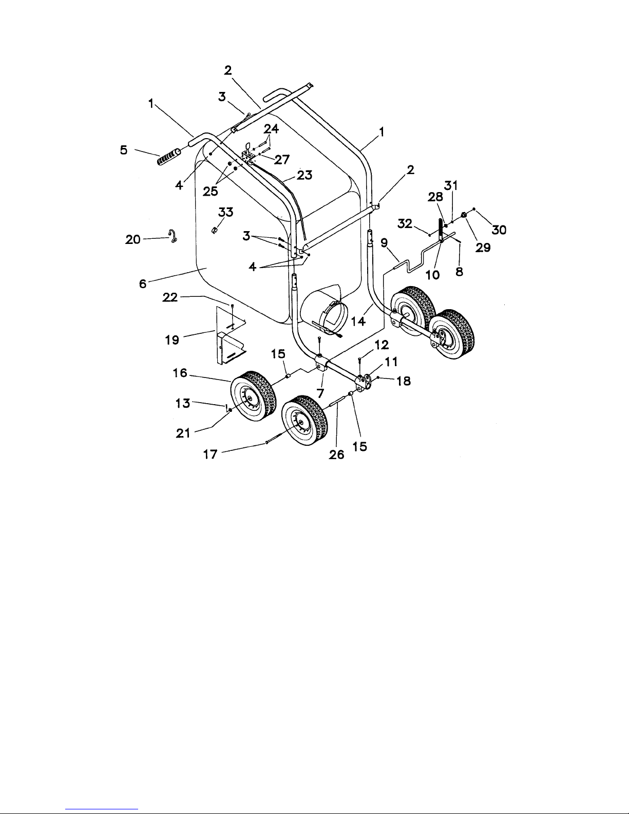
NOTE: The numbers used in the following steps refer to those used in the parts list and exploded view of the Handle and Bag
Assembly on Page 7.
1. Remove the four hex hd. bolts (3), lock nuts (4), and the lower cross brace (2) from the top of the lower handles (14).
2. Slide the upper handle assembly down over the top of the lower handles (14).
3. Reassemble the hardware removed in Step 1, making sure the lower cross brace (14) is assembled to the top holes
and bolts.
ATTACHING CLUTCH CABLE - TRACTION MODELS ONLY
1. The clutch cable is preassembled to the upper handle assembly in the correct position. Once the handles are
completely assembled it must be connected to the clutch arm weldment.
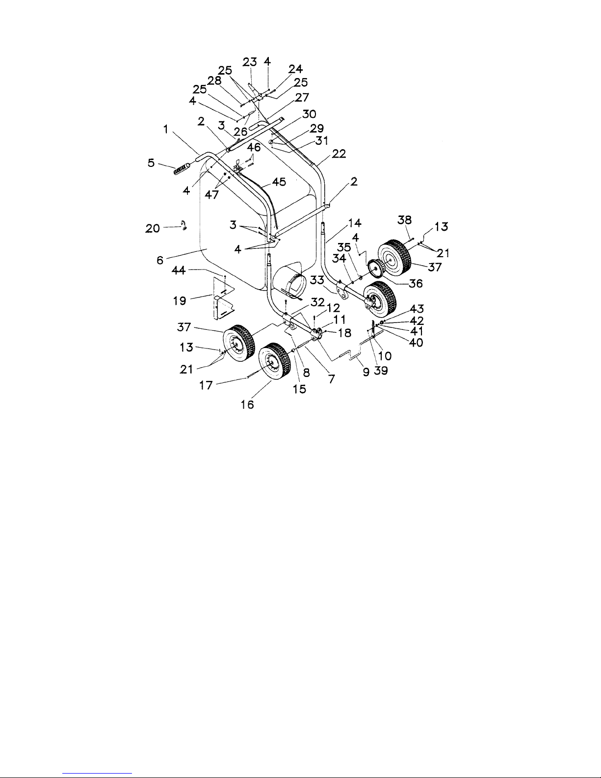
NOTE: The numbers used in the following steps refer to those used in the parts list and exploded view of the housing and
drive assembly on Page 8 and 9.
2. Remove the round hd. machine screw (51) used to secure the throttle cable clip (19) to the side plate (18).
3. Place throttle cable clip around clutch cable. Lift the clutch handle to release tension in the clutch cable.
4. Attach hook at the end of the cable into the hole in the clutch arm weldment (21).
5. Place the clip against side plate in its proper location and replace screw.
OPERATING INSTRUCTIONS
READ SAFETY & OPERATING INSTRUCTIONS BEFORE OPERATING
ENGINE OPERATION
CAUTION: The engine contains NO OIL. Before starting the engine, make sure the crankcase is filled with the proper amount
and type of oil. Refer to the Engine Operating Manual for proper lubrication of the engine. Read the Engine Manual carefully
before operating unit.
TO ASSEMBLE HANDLES
NOTE: The numbers used in the following steps refer to those used in the parts list and exploded view of the Handle and Bag
Assembly on Page 7.
1. Remove the four hex hd. bolts (3), lock nuts (4), and the lower cross brace (2) from the top of the lower handles (14).
2. Slide the upper handle assembly down over the top of the lower handles (14).
3. Reassemble the hardware removed in Step 1, making sure the lower cross brace (14) is assembled to the top holes
and bolts.
MAINTENANCE INSTRUCTIONS
OBSERVE SAFETY RULES AT ALL TIMES.
WARNING: DO NOT WORK ON SCAVENGER with engine running or idling. Bring to a complete stop. Remove spark plug
wire on engine.
1. For servicing and operating instructions for engine refer to Engine Manufacturers Service Manual. Careful attention to
care of air cleaner and crankcase lubrication instructions will insure longer engine life. KEEP ENGINE CLEAN.
2. Clean the engine air cleaner every 10 hours of operation. (Do so more often under dusty conditions.) If it is punctured,
torn, or uncleanable, it should be replaced.
3. Be sure to keep the oil at the proper level in the engine. Check the oil level each time you fill the fuel tank.
4. To drain the crankcase oil from the engine, use a siphon pump. To use it, run the engine for a short time to warm the oil
and make it flow more easily. Then remove the cap from the filler hole in the engine and insert the plastic tube into the
hole. Hold the pump below the bottom of the crankcase and squeeze it several times until oil appears in the tube above
the pump, and allow the oil to siphon into a container for disposal. DISPOSE OF PROPERLY.
5. Once a year, remove the wheels and add fresh grease in the teeth of the gears.
6. DUST BAG CARE
a. Keep the dust bag clean at all times.
b. To clean the dust bag, turn the bag inside out and reattach to the sweeper.
c. Start the engine and run at full throttle. Lightly tap the bag to release the dust trapped in the weave.
d. When the bag is clean remove it and turn it right side out again. Reattach to the sweeper and resume sweeping.
e. DO NOT wash the dust bag to clean. Washing will shrink the material, reducing air flow through the bag and seriously
reduce vacuum.
7. The efficiency of this unit depends on the breathing capacity of the dust bag. Under extremely dusty conditions the bag
should be emptied and cleaned frequently. Always empty and clean bag before storing after use. Debris allowed to
remain in the bag may cause spontaneous combustion, resulting in an explosion or fire.