Miracle Water MW-30 User manual

Installation and Operation Manual
Model MW-30
How to maintain and operate
your Demand Controlled
Water Softener
DO NOT RETURN TO STORE
If you have questions or concerns when
installing, operating or maintaining your
softener, visit www.leaumiraclewater.ca
or call our toll free number:
1-800-356-7851
7301415 (Rev. D 10/14/08)
System tested and certified by NSF International
against NSF/ANSI Standard 44
for water softener performance.
System tested and certified by the Water Quality
Association against CSA B483.1.

2Miracle Water Installation & Operation Manual
Table of Contents
Unpacking and Inspection . . . . . . . . . . . . . . . . . . . . . . . . . . . . . . . . . . . . . . . . . . . . . . . . . . . . . . . . . . . . . . .3
Dimensions/Specifications . . . . . . . . . . . . . . . . . . . . . . . . . . . . . . . . . . . . . . . . . . . . . . . . . . . . . . . . . . . . . . .4
Wiring Schematic . . . . . . . . . . . . . . . . . . . . . . . . . . . . . . . . . . . . . . . . . . . . . . . . . . . . . . . . . . . . . . . . . . . . . . .4
Miscellaneous Service Information . . . . . . . . . . . . . . . . . . . . . . . . . . . . . . . . . . . . . . . . . . . . . . . . . . . . . . . . . . . .5
Salt Storage Capacities . . . . . . . . . . . . . . . . . . . . . . . . . . . . . . . . . . . . . . . . . . . . . . . . . . . . . . . . . . . . . . . . . . . . .5
Safety Guides . . . . . . . . . . . . . . . . . . . . . . . . . . . . . . . . . . . . . . . . . . . . . . . . . . . . . . . . . . . . . . . . . . . . . . . . . .6
Water Conditioning Information . . . . . . . . . . . . . . . . . . . . . . . . . . . . . . . . . . . . . . . . . . . . . . . . . . . . . . . . . . .6
Water Conditioning . . . . . . . . . . . . . . . . . . . . . . . . . . . . . . . . . . . . . . . . . . . . . . . . . . . . . . . . . . . . . . . . . . . . . . . . .6
Assembly . . . . . . . . . . . . . . . . . . . . . . . . . . . . . . . . . . . . . . . . . . . . . . . . . . . . . . . . . . . . . . . . . . . . . . . . . . . . .8
Planning Installation . . . . . . . . . . . . . . . . . . . . . . . . . . . . . . . . . . . . . . . . . . . . . . . . . . . . . . . . . . . . . . . . . . . .9
Inlet - Outlet Plumbing Options . . . . . . . . . . . . . . . . . . . . . . . . . . . . . . . . . . . . . . . . . . . . . . . . . . . . . . . . . . . . . . .9
Other Requirements . . . . . . . . . . . . . . . . . . . . . . . . . . . . . . . . . . . . . . . . . . . . . . . . . . . . . . . . . . . . . . . . . . . . . . .10
Tools and Materials You May Need . . . . . . . . . . . . . . . . . . . . . . . . . . . . . . . . . . . . . . . . . . . . . . . . . . . . . . . . . . .10
Select Installation Location . . . . . . . . . . . . . . . . . . . . . . . . . . . . . . . . . . . . . . . . . . . . . . . . . . . . . . . . . . . . . . . . . .11
Optional Weather Protection . . . . . . . . . . . . . . . . . . . . . . . . . . . . . . . . . . . . . . . . . . . . . . . . . . . . . . . . . . . . . .12
Installation . . . . . . . . . . . . . . . . . . . . . . . . . . . . . . . . . . . . . . . . . . . . . . . . . . . . . . . . . . . . . . . . . . . . . . . . . . .12
Step 1. Turn Off Water Supply . . . . . . . . . . . . . . . . . . . . . . . . . . . . . . . . . . . . . . . . . . . . . . . . . . . . . . . . . . . . . . .12
Step 2. Move the Unit into Place . . . . . . . . . . . . . . . . . . . . . . . . . . . . . . . . . . . . . . . . . . . . . . . . . . . . . . . . . . . . .12
Step 3. Assemble Inlet and Outlet Plumbing . . . . . . . . . . . . . . . . . . . . . . . . . . . . . . . . . . . . . . . . . . . . . . . . . . . .13
Step 4. Connect Inlet and Outlet Plumbing . . . . . . . . . . . . . . . . . . . . . . . . . . . . . . . . . . . . . . . . . . . . . . . . . . . . .13
Step 5. Cold Water Pipe Grounding . . . . . . . . . . . . . . . . . . . . . . . . . . . . . . . . . . . . . . . . . . . . . . . . . . . . . . . . . . .14
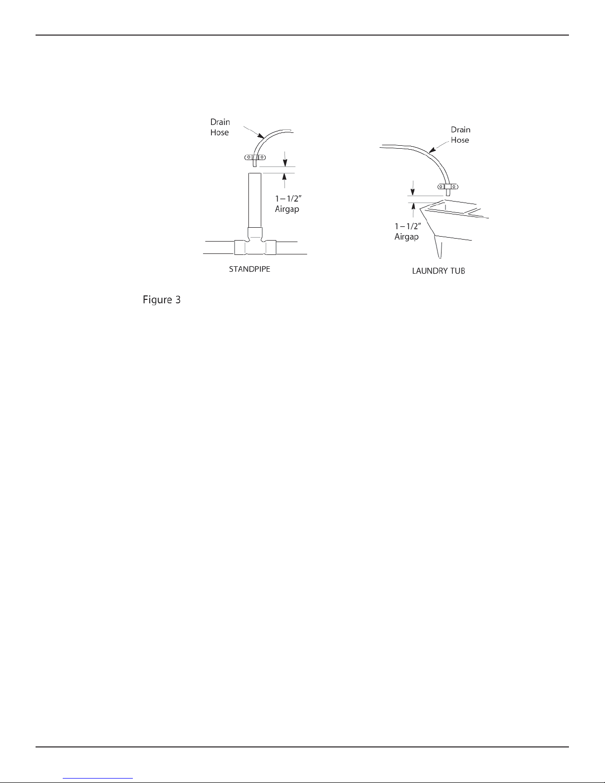
Step 6. Install Valve Drain Hose . . . . . . . . . . . . . . . . . . . . . . . . . . . . . . . . . . . . . . . . . . . . . . . . . . . . . . . . . . . . . .14
Step 7. Install Salt Storage Tank Overflow Hose . . . . . . . . . . . . . . . . . . . . . . . . . . . . . . . . . . . . . . . . . . . . . . . . .14
Step 8. Pressure Testing for Leaks . . . . . . . . . . . . . . . . . . . . . . . . . . . . . . . . . . . . . . . . . . . . . . . . . . . . . . . . . . .15
Step 9. Add Water and Salt to the Salt Storage Tank . . . . . . . . . . . . . . . . . . . . . . . . . . . . . . . . . . . . . . . . . . . . .15
Step 10. Sanitizing the Softener . . . . . . . . . . . . . . . . . . . . . . . . . . . . . . . . . . . . . . . . . . . . . . . . . . . . . . . . . . . . . .15
Step 11. Connect Transformer . . . . . . . . . . . . . . . . . . . . . . . . . . . . . . . . . . . . . . . . . . . . . . . . . . . . . . . . . . . . . . .16
Step 12. Install the Salt Hole and Faceplate Cover(s) . . . . . . . . . . . . . . . . . . . . . . . . . . . . . . . . . . . . . . . . . . . . .16
Step 13. Start a Recharge . . . . . . . . . . . . . . . . . . . . . . . . . . . . . . . . . . . . . . . . . . . . . . . . . . . . . . . . . . . . . . . . . .16
Step 14. Restart the Water Heater . . . . . . . . . . . . . . . . . . . . . . . . . . . . . . . . . . . . . . . . . . . . . . . . . . . . . . . . . . . .16
Programming the Faceplate Timer . . . . . . . . . . . . . . . . . . . . . . . . . . . . . . . . . . . . . . . . . . . . . . . . . . . . . . . .17
Step 1. Set Time of Day . . . . . . . . . . . . . . . . . . . . . . . . . . . . . . . . . . . . . . . . . . . . . . . . . . . . . . . . . . . . . . . . . . . .17
Step 2. Set Water Hardness Number . . . . . . . . . . . . . . . . . . . . . . . . . . . . . . . . . . . . . . . . . . . . . . . . . . . . . . . . . .18
Step 3. Set Recharge (Regeneration) Time . . . . . . . . . . . . . . . . . . . . . . . . . . . . . . . . . . . . . . . . . . . . . . . . . . . . .18
Step 4. Set Salt Efficiency . . . . . . . . . . . . . . . . . . . . . . . . . . . . . . . . . . . . . . . . . . . . . . . . . . . . . . . . . . . . . . . . . .19
Customizing Features/Options . . . . . . . . . . . . . . . . . . . . . . . . . . . . . . . . . . . . . . . . . . . . . . . . . . . . . . . . . . .20
Recharge Now . . . . . . . . . . . . . . . . . . . . . . . . . . . . . . . . . . . . . . . . . . . . . . . . . . . . . . . . . . . . . . . . . . . . . . . . . . .20
Recharge Tonight . . . . . . . . . . . . . . . . . . . . . . . . . . . . . . . . . . . . . . . . . . . . . . . . . . . . . . . . . . . . . . . . . . . . . . . . .20
Timer “Power-Outage Memory” . . . . . . . . . . . . . . . . . . . . . . . . . . . . . . . . . . . . . . . . . . . . . . . . . . . . . . . . . . . . . .20
Adjustable Backwash . . . . . . . . . . . . . . . . . . . . . . . . . . . . . . . . . . . . . . . . . . . . . . . . . . . . . . . . . . . . . . . . . . . . . .21
Adjustable Fast Rinse . . . . . . . . . . . . . . . . . . . . . . . . . . . . . . . . . . . . . . . . . . . . . . . . . . . . . . . . . . . . . . . . . . . . .21
Routine Maintenance . . . . . . . . . . . . . . . . . . . . . . . . . . . . . . . . . . . . . . . . . . . . . . . . . . . . . . . . . . . . . . . . . . .22
Adding Salt . . . . . . . . . . . . . . . . . . . . . . . . . . . . . . . . . . . . . . . . . . . . . . . . . . . . . . . . . . . . . . . . . . . . . . . . . . . . . .22
Breaking A Salt Bridge . . . . . . . . . . . . . . . . . . . . . . . . . . . . . . . . . . . . . . . . . . . . . . . . . . . . . . . . . . . . . . . . . . . . .22
Cleaning the Nozzle and Venturi . . . . . . . . . . . . . . . . . . . . . . . . . . . . . . . . . . . . . . . . . . . . . . . . . . . . . . . . . . . . .23
Protect the Water Softener from Freezing . . . . . . . . . . . . . . . . . . . . . . . . . . . . . . . . . . . . . . . . . . . . . . . . . . . . . .24
Troubleshooting Guide . . . . . . . . . . . . . . . . . . . . . . . . . . . . . . . . . . . . . . . . . . . . . . . . . . . . . . . . . . . . . . . . .25
Automatic Electronic Diagnostics . . . . . . . . . . . . . . . . . . . . . . . . . . . . . . . . . . . . . . . . . . . . . . . . . . . . . . . . . . . . .26
Manual Advance Diagnostics . . . . . . . . . . . . . . . . . . . . . . . . . . . . . . . . . . . . . . . . . . . . . . . . . . . . . . . . . . . . . . . .26
Manual Advance Regeneration Check . . . . . . . . . . . . . . . . . . . . . . . . . . . . . . . . . . . . . . . . . . . . . . . . . . . . . . . . .27
Softener Components . . . . . . . . . . . . . . . . . . . . . . . . . . . . . . . . . . . . . . . . . . . . . . . . . . . . . . . . . . . . . . . . . .29
Warranty . . . . . . . . . . . . . . . . . . . . . . . . . . . . . . . . . . . . . . . . . . . . . . . . . . . . . . . . . . . . . . . . . . . . . . . . . . . . .30

3
Miracle Water Installation & Operation Manual
Unpacking and Inspection
The parts required to assemble and install the unit are included in a parts bag.
Thoroughly check the unit for possible shipping damage and parts loss. Also inspect and note any
damage to the shipping carton.
Remove and discard (RECYCLE) all packing materials. To avoid loss of small parts, we suggest
you keep the small parts in the parts bag until you are ready to use them.
DO NOT RETURN TO STORE
If you have any questions, missing parts or damage, please call 1-800-356-7851
Before you call please have your model number, date of purchase, water conditions
and number of people in your home.
For more installation or service information visit www.leaumiraclewater.ca
FOR FUTURE REFERENCE, ENTER THE FOLLOWING INFORMATION
MODEL NO. 12 _____________________ SERIAL NO. 12 __________________ _ _ _ _ _ _
CODE 1_____________________ INSTALLATION DATE ____________________
WATER HARDNESS _____________GPG IRON CONTENT _____________________PPM
1on registration decal 2on shipping carton

4Miracle Water Installation & Operation Manual
Dimensions/ Specifications
MODEL NOMINAL RESIN TANK SIZE A B C
MW-30 9” DIA. X 35” 37” 33” 42”
Wiring Schematic

5
Miracle Water Installation & Operation Manual
Miscellaneous Service Information
DESIGN SPECIFICATION MW-30
FILL CYCLE 1FLOW .3 gpm
BRINE CYCLE 2FLOW .22 gpm
BRINE RINSE CYCLE 2FLOW .15 gpm
BACKWASH CYCLE (MAX.) 2FLOW 2.0 gpm
FAST RINSE CYCLE (MAX.) 2FLOW 2.0 gpm
1gallon per minute flow to brine tank
2gallon per minute flow to drain
Salt Storage Capacity
MW-30 - 150 lbs.
Product Specifications
MW-30
Rated Service Flow Rate (gpm) 8.0
Amount of High Capacity Ion Exchange Resin (cu ft) .82
Pressure Drop at Rated Service Flow (psig) 12
Water Supply Max. Hardness (gpg) 95
Water Supply Max. Clear Water Iron (ppm) 5
Water Pressure Limits (min./max. psi) 20 - 100
Min. - Max. Water Temperature (oF) 40 - 120
Min. Water Supply Flow Rate (gpm) 3
Max. Drain Flow Rate (gpm) 2.0
Performance Claims
MW-30
Rated Softening Capacity (Grains @ 14,700 @ 2.9
Pound Salt Dose) 25,400 @ 8.0
30,100 @ 13.1
Rated Efficiency (Grains/Pound of 5060 @ 2.9 lbs.
Salt @ Minimum Salt Dose
This system conform to NSF/ANSI 44 for the specific performance claims as
verified and substantiated by test data.
The efficiency rating is only valid at the minimum stated salt dose. This soften-
er is efficiency rated according to NSF/ANSI Standard 44.

6Miracle Water Installation & Operation Manual
Safety Guides
Follow the installation instructions carefully. (Failure to install the unit properly voids the war-
ranty.)
Before you begin installation, read this entire manual. Then, obtain all the materials and tools you
will need to make the installation.
Check local plumbing and electrical codes. The installation must conform to them.
Use only lead-free solder and flux for all sweat-solder connections, as required by state and fed-
eral codes.
Use care when handling the unit. Do not turn upside down, drop, or set on sharp protrusions.
Do not locate the unit where freezing temperatures occur. Do not attempt to treat water over 120oF.
Freezing, or hot water damage voids the warranty.
Avoid installing in direct sunlight. Excessive sun heat may cause distortion or other damage to
non-metallic parts.
The unit requires a minimum water flow of 3 gallons per minute at the inlet. Maximum allowable
inlet water pressure is 100 psi. If daytime pressure is over 80 psi, nighttime pressure may
exceed the maximum. Use a pressure reducing valve if necessary. (Adding a pressure reducing
valve may reduce the flow.)
The unit works on 24 volt-60 hz electrical power only. Be sure to use the included transformer
and plug it into a nominal 120V, 60 cycle household outlet that is grounded and properly protect-
ed by an overcurrent device such as a circuit breaker or fuse. If transformer is replaced, use only
the authorized service, Class II, 24V 10VA transformer.
This system is not intended to be used for treating water that is microbiologically unsafe or of
unknown quality without adequate disinfection before or after the system. For California installa-
tions the Salt Efficiency setting must be set to “ON”.
European Directive 2002/96/EC requires all electrical and electronic equipment to be dis-
posed of according to Waste Electrical and Electronic Equipment (WEEE) requirements.
This directive or similar laws are in place nationally and can vary from region to region.
Please refer to your province and local laws for proper disposal of this equipment.
Water Conditioning Information
Water Conditioning
Water conditioning is the treatment of four general conditions. These are:
1. HARDNESS
2. IRON
3. ACIDITY
4. SEDIMENTS
1. HARDNESS is a term to describe the presence of calcium and magnesium minerals in water. A
chemical analysis accurately measures the amount of minerals in grain weight. For example,
one gallon of water with 5 grains per gallon (gpg) hardness has dissolved minerals, that if solid-
ified, about equals the size of one ordinary aspirin tablet. One gallon of water, 25 gpg hard, has
a mineral content equal in size to 5 aspirin tablets. Water hardness varies greatly across the
country. It generally contains from 3 to 100 gpg.
Hard water affects living in general. Hardness minerals combine with soap to make a soap curd.
The curd greatly reduces the cleaning action of soap. Precipitated hardness minerals form a
crust on cooking utensils, appliances, and plumbing fixtures. Even the tastes of foods are affect-

7
Miracle Water Installation & Operation Manual
ed. A water softener removes the hardness minerals to eliminate these problems, and others.
Sodium Information: Water softeners using sodium chloride (salt) for regeneration and add
sodium to the water. Persons on sodium restricted diets should consider the added sodium as
part of their overall intake.
2. IRON in water is measured in parts per million (ppm). The total* ppm of iron, and type or types*,
is determined by chemical analysis. Four different types of iron in water are:
1Ferrous (clear water),
2Ferric (red water),
3Bacterial and organically bound iron,
4Colloidal and inorganically bound iron (ferrous or ferric).
*Water may contain one or more of the four types of iron and any combination of these. Total
iron is the sum of the contents.
1Ferrous (clear water) iron is soluble and dissolves in water. It is usually detected by taking a
sample of water in a clear bottle or glass. Immediately after taking, the sample is clear. As the
water sample stands, it gradually clouds and turns slightly yellow or brown as air oxidizes the
iron. This usually occurs in 15 to 30 minutes. This unit will reduce moderate amounts of this
type of iron (see specifications).
When using the softener to remove Ferrous (clear water) iron, add 5 grains to the hard-
ness setting for every 1 ppm of Ferrous (clear water) iron.
2Ferric (red water), and 3Bacterial and organically bound irons are insoluble. This iron is vis-
ible immediately when drawn from a faucet because it has oxidized before reaching the home.
It appears as small cloudy yellow, orange, or reddish suspended particles. After the water stands
for a period of time, the particles settle to the bottom of the container. Generally these irons are
removed from water by filtration. Chlorination is also recommended for bacterial iron. This unit
will not reduce ferric or bacterial iron.
4Colloidal and inorganically bound iron is of ferric or ferrous form that will not filter or exchange
out of water. In some instances, treatment may improve colloidal iron water, but always CON-
SULT A QUALIFIED WATER CHEMISTRY LAB before attempting to treat it. Colloidal iron water
usually has a yellow appearance when drawn. After standing for several hours, the color per-
sists and the iron does not settle, but remains suspended in the water.
Iron in water causes stains on clothing and plumbing fixtures. It negatively affects the taste of
food, drinking water, and other beverages. This unit will not reduce colloidal iron.
3. ACIDITY or acid water is caused by carbon dioxide, hydrogen sulfide, and sometimes industri-
al wastes. It is corrosive to plumbing, plumbing fixtures, water heaters, and other water using
appliances. In can also damage and cause premature failure of seals, diaphragms, etc., in water
handling equipment.
A chemical analysis is needed to measure the degree of acidity in water. This is called the pH
of water. Water testing below 6.9 pH is acidic. The lower the pH reading, the greater the acidi-
ty. A neutralizer filter or a chemical feed pump are usually recommended to treat acid water.
4. SEDIMENT is fine, foreign material particles suspended in water. This material is most often clay
or silt. Extreme amounts of sediment may give the water a cloudy appearance. A sediment fil-
ter installed ahead of the water softener normally corrects this situation.

8Miracle Water Installation & Operation Manual
Assembly
1. Miracle Water models are factory assembled. During installation, remove the Salt Hole Cover.
Set aside to prevent damage. Check the brinewell to be sure it is secured and vertical (see
Figure 1). Slide Faceplate Cover forward to expose back valve assembly.
2. Lift the brine valve out of the brinewell. Be sure the float stem is parallel to stand tube so seals
will seat properly during operation. Replace the brine valve in the brinewell bottom and install
the Brinewell Cover.
3. Install the brine tank overflow grommet and elbow in the 13/16” diameter hole in the back of the
salt storage tank sidewall.

Hard
Water
Conditioned
Water
Floor Drain
Salt Storage Tank
Overflow Hose*
1---1/2” Airgap
INLET
OUTLET
Valve
Drain
Hose*
Single Valve
Bypass System
Transformer
To T i m e r
3/4” coupling
3/4” pipe and fittings
Copper tube
Gasket & Nut
3/4” pipe
3/4” coupling
Copper tube
Nut
Gasket
Bypass valve
Clips
To O u t si d e
Facets
*Do not tee these
drain lines together
9
Miracle Water Installation & Operation Manual
Planning Installation
Inlet - Outlet Plumbing Options
• ALWAYS INSTALL either a single bypass valve (included) or a 3 valve bypass system (not
included). Bypass valves allow you to turn off water to the softener for repairs if needed, but still
have water in house pipes.
• Use 3/4” (minimum) pipe and fittings.
• Use sweat copper... or, threaded pipe... or, PVC plastic pipe... or, other approved plumbing.
Tie or wire valve drain hose in place, to keep over
floor drain.
NOTE: Air gap requirements on Fig. 2
NOTE: Salt Hole and Faceplate cover not
shown for clarity of drawing.
NOTE: The bypass valve allows the water to
be turned off to the softener for
servicing, but still have water in the
house pipes.
Figure 2
MAIN WATER PIPE

10 Miracle Water Installation & Operation Manual
Other Requirements
• A 120V-60Hz, grounded electrical outlet (continuously ‘‘live’’) is needed within 10’ of the unit.
• A drain is needed for regeneration discharge water. A floor drain, close to the unit, is preferred.
A laundry tub, standpipe, etc., are other drain options.
Tools and Materials You May Need
• Common Screwdriver • Tape Measure
•Pliers • Pipe and fittings as required
Soldered Copper
• Tubing cutter • LEAD-FREE solder and flux
• Propane torch •Emery cloth, sandpaper or steel wool
• Misc. fittings
Threaded
• Pipe cutter or hacksaw • Pipe joint compound
• Threading tool • Misc. fittings
CPVC Plastic
• Pipe cutter • Solvent cement
• Hacksaw • Primer
• Adjustable wrench • Misc. fittings
NOTE: The salt storage tank drain elbow accepts either 1/2” or 3/8” I. D. hose.

11
Miracle Water Installation & Operation Manual
*VALVE DRAIN OPTIONS: Flexible drain hose is not allowed in all localities (check your plumb-
ing codes). For a rigid valve drain run, cut the barbed section off the drain fitting for access to the
1/4” pipe threads. Then plumb a rigid drain as needed (see Figure 4).
Select Installation Location
Consider all of the following when selecting an installation location for the unit.
• To condition all water in the home, install the unit close to the water supply inlet, and before all
other plumbing connections, EXCEPT outside water pipes. Outside faucets should remain on
hard water to avoid wasting conditioned water and salt.
• A nearby drain is needed to carry away regeneration discharge water. Use a floor drain, laundry
tub, sump, standpipe, etc., or other options (check your local codes).
• The unit works on 24 volts only. A transformer, with a 10’ power cord attached, is included to
reduce 120-60 Hz household electrical power. Provide an approved, grounded outlet within 10’
of the unit.
• Always install the unit BEFORE the water heater and after all other installed water condition-
ing equipment (see Figure 5 below).

12 Miracle Water Installation & Operation Manual
Installation
Step 1. Turn Off Water Supply
1. Close the main water supply valve, near the well pump or water meter.
2. Shut off the electric or fuel supply to the water heater.
3. Open all faucets to drain all water from the house pipes.
Step 2. Move the Unit into Place
Move the unit into installation position. Set it on a solid, smooth and level surface. If needed, place
the unit on a section of plywood, a minimum of 3/4” thick. Then, shim under the plywood to level
the unit, see Figure7.
CAUTION: DO NOT PLACE SHIMS DIRECTLY UNDER THE SALT STORAGE TANK. The
weight of the tank, when full of water and salt, may cause the tank to fracture at
the shim.

13
Miracle Water Installation & Operation Manual
Visually check and remove any foreign materials from the valve inlet and outlet ports.
If not already done, put a light coating of silicone grease or Vaseline on the bypass valve o-rings.
Push the bypass valve into the softener valve as far as it will go. Snap the 2 large holding clips
into place, from the top down as shown in Figure 8.
CAUTION: Be sure the clips snap firmly into place so the bypass valve will not pull out.
Step 3. Assemble Inlet and Outlet Plumbing
Measure, cut, and loosely assemble pipe and fittings from the main water pipe to the inlet and out-
let ports of the valve.
Be sure hard water supply pipe goes to the valve inlet side.
NOTE: Inlet and outlet are marked on the valve. Trace the water flow direction to be sure.
CAUTION: Be sure to fit, align and support all plumbing to prevent putting stress on the
softener valve inlet and outlet. Undo stress may cause damage to the valve.
Step 4. Connect Inlet and Outlet Plumbing
Complete the inlet and outlet plumbing as applicable, below.
1. SOLDERED COPPER
a. Thoroughly clean and flux all joints.
b. Make all solder connections. Be sure to keep fittings fully together, and pipes square and
straight. DO NOT solder with installation adaptors or bypass valve attached to plumbing.
Soldering heat will damage the installation adaptors and valve.
2. THREADED PIPE
a. Apply pipe joint compound to all outside pipe threads.
b. Tighten all threaded joints.
3. PVC PLASTIC PIPE
a. Clean, prime and cement all joints, following the manufacturer’s instructions supplied with the
plastic pipe and fittings.

14 Miracle Water Installation & Operation Manual
Step 5. Cold Water Pipe Grounding
WARNING: The house cold water pipe (metal only) is often used as a ground for the house
electrical system. The 3-valve bypass type of installation, shown in Figure. 2,
will maintain ground continuity. If you use a plastic bypass valve at the unit,
continuity is broken. To restore the ground, do the following.
Install a #4 copper wire across the removed section of main water pipe, securely clamping at both
ends, see Figure 9 (parts not included).
NOTE: Check local plumbing and electrical codes for proper installation of the ground
wire. The installation must conform to them. In Massachusetts, plumbing codes of
Massachusetts shall be adhered to. Consult with your licensed plumber.
Step 6. Install Valve Drain Hose
NOTE: See valve drain options on page 11.
1. Connect a length of 3/8” or 7/16” I.D. hose (check codes) to the valve drain elbow, on the con-
troller, see Figure 4. Use a hose clamp to hold the hose in place. Route the hose out through the
notch in the Faceplate Cover.
2. Run the hose to the floor drain, and as typically shown in Figure 2, tie or wire the end to a brick
or other heavy object. This will prevent ‘‘whipping’’ during regenerations. Be sure to provide a 1-
1/2” minimum air gap, to prevent possible sewer water backup.
NOTE: In addition to a floor drain, you can use a laundry tub, or standpipe as a good drain
point for this hose. Avoid long drain hose runs, or elevating the hose more than 8’
above the floor.
Step 7. Install Salt Storage Tank Overflow Hose
1. Connect a length of 3/8” I. D. hose to the salt storage tank overflow elbow and secure in place
with a hose clamp (see Figure 2).
2. Run the hose to the floor drain, or other suitable drain point no higher than the drain fitting on
the salt storage tank. (This is a gravity drain.) If the tank overfills with water, the excess water
flows to the drain point.
NOTE: Route the tubing neatly out of the way and cut it to the desired length.
DO NOT connect the valve drain tubing from step 6 to the salt storage tank over flow hose.

15
Miracle Water Installation & Operation Manual
Step 8. Pressure Testing for Leaks
To prevent excessive air pressure in the unit and plumbing system, do the following steps
EXACTLY in order.
1. Fully open two or more softened cold water faucets nearby the unit.
2. Place the bypass valve(s) in “bypass” position. See Figure 10.
3. Fully open the main water supply valve. Observe steady flow from the opened faucets, with no
air bubbles.
4. EXACTLY as follows, place bypass valve(s) in “service”.
a. SINGLE BYPASS VALVE: SLOWLY, move the valve stem toward “service”, pausing several
times to allow the unit to pressurize slowly.
b. 3-VALVE BYPASS: Fully close the bypass valve and open the outlet valve. SLOWLY, open
the inlet valve, pausing several times to allow the unit to pressurize slowly.
5. After about three minutes, open a hot water faucet for about one minute, or until all air is
expelled, then close.
6. Close all cold water faucets and check your plumbing work for leaks.
Step 9. Add Water and Salt to the Salt Storage Tank
1. Using a container, add about one gallon of clean water into the salt storage tank.
2. Add salt pellets to the salt storage tank.
NOTE: See page 23 for additional information on salt.
Step 10. Sanitizing the Softener
Care is taken at the factory to keep your unit clean and sanitary. Materials used to make the unit
will not infect or contaminate your water supply, and will not cause bacteria to form or grow.
However, during shipping, storage, installing and operating, bacteria could get into the unit. For this
reason, sanitizing as follows is suggested1when installing.
1Recommended by the Water Quality Association. On some water supplies, the unit may need periodic disinfecting.
1. Remove the Brinewell Cover and pour about 1-1/2 oz. (2 to 3 tablespoons) of common house-
hold bleach into the softener brinewell, Figure 1, page 9. Clorox, Linco, Bo Peep, White Sail, Eagle,
etc. are brand names of bleach readily available. Replace the Brinewell Cover.
2. The final step in the sanitizing procedure is done as you complete the following steps, including
timer programming on page 18.
3. This process will flush out all sanitizing solution and condition the unit.
Single Valve Bypass
PUSH IN
for Bypass
PULL OUT
for Service

16 Miracle Water Installation & Operation Manual
Step 11. Connect Transformer
NOTE: Check to be sure all leadwire connectors are secure on the back of the electronic
board.
CAUTION: Be sure all wiring is away from the valve gear and motor area, which rotates dur-
ing regenerations.
1. Plug the transformer into a continuously “live”, grounded house electrical outlet, approved by
local codes. THE UNIT WORKS ON 24V ONLY. DO NOT CONNECT WITHOUT THE TRANS-
FORMER.
Step 12. Install the Salt Hole and Faceplate Cover(s)
Complete the Programming Steps on Pages 18, 19 and 20.
Step 13. Start a Recharge
Press the (RECHARGE) button and hold for three seconds until Recharge Now begins
to flash in the timer display, starting a recharge. This recharge draws the sanitizing bleach into and
through the unit. Any air remaining in the unit is purged to the drain.
Step 14. Restart the Water Heater
Turn on the electricity or fuel supply to the water heater, and light the pilot, if applicable.
NOTE: The water heater is filled with HARD water and, as hot water is used, it refills with
conditioned water. In a few days, the hot water will be fully conditioned. To have
fully conditioned hot water immediately, wait until the recharge (Step 13) is over.
Then, drain the water heater until water runs cold.

17
Miracle Water Installation & Operation Manual
Programming the Faceplate Timer
Figure 12
If you have questions about installation, programming, operating and routine maintenance...
call 1-800-356-7851
When the transformer is plugged into the electrical outlet, a model code and a test number (exam-
ple:
s3.0), begins to flash in the faceplate display. Then, 12:00 AM and PRESENT TIME begins to flash.
NOTE: If SR --or ----shows in the display, press the UP Lor DOWN Mbutton until LE31
shows. Then, press the SELECT/MENU button to set, and change to the
flashing PRESENT TIME display.
Step 1. Set Time of Day
If the words PRESENT TIME do not show in the display, press the (Select/Menu) button
until they do.
1. Press the UP Lor DOWN Mbuttons to set the present time. UP Lmoves the display ahead;
DOWN Mmoves the time backward.
Be sure AM or PM, is correct.
NOTE: Press buttons and quickly release to slowly advance the display. Hold for fast
advance. This procedure applies for all following settings.
SELECT
MENU
SELECT
MENU

18 Miracle Water Installation & Operation Manual
Step 2. Set Water Hardness Number
1. Press the (Select/Menu) button once to display a flashing 25 and HARDNESS.
2. Press the UP Lor DOWN Mbuttons to set your water hardness number.
NOTE: Be sure to enter the grains per gallon (gpg) hardness of your water supply on page
4, for future reference. If your water supply contains iron, compensate for it by
adding to the water hardness number. For example, assume your water is 20 gpg
hard and contains 2 ppm iron. Add 5 to the hardness number for each 1 ppm of
iron. In this example, you would use 30 for your hardness number.
20 gpg hardness
2 ppm iron x 5 = 10 +10
(times) 30 HARDNESS NUMBER
Step 3. Set Recharge (Regeneration) Time
1. Press the (Select/Menu) button once to display a flashing 2:00AM and RECHARGE
TIME.
If no change is desired, go to Step 4. If you want to change the recharge start time, press the
UP Lor DOWN Mbuttons until the desired starting time shows.
SELECT
MENU
SELECT
MENU

19
Miracle Water Installation & Operation Manual
Step 4. Set Salt Efficiency
When this feature is ON, the unit will operate at salt efficiencies of 4000 grains of hardness per
pound of salt or higher. (May recharge more often using smaller salt dosage and less water).
1. Press and hold the (Select/Menu) button until the following screen is displayed.
Once in this display, press the (Select/Menu) button and one of the following two dis-
plays is shown.
2. Press the UP Lor DOWN Mbuttons to set On or Off. When set to On, the efficiency icon will
be displayed in the upper right hand corner of the normal run display.
3. Press the (Select/Menu) button once again, to complete initial programming.
If you have questions about installation, programming, operating and routine maintenance...
call 1-800-356-7851
Salt Efficiency Feature
Your Miracle Water Softener has a “High Efficiency” feature with an “ON” or “OFF” setting. This
softener setting is shipped in the “OFF” position, which utilizes the maximum rated capacity while
most often achieving maximum salt efficiencies. Turning this setting to the “ON” position may ini-
tiate more frequent recharges, however it will operate at 4000 grains per pound of salt or higher.
If you wish to turn the Salt Efficiency feature “ON” ( icon will show in display), follow the instruc-
tions on this page.
SELECT
MENU
SELECT
MENU
SELECT
MENU

20 Miracle Water Installation & Operation Manual
Customizing Features/Options
Recharge Now
If you have guests, or other times when more water than usual is used, you could begin to run out
of conditioned water. If the unit is not scheduled to regenerate for another day or two, you could
get hard water until then. If this occurs, do the following to start an immediate regeneration.
• Press and hold the (Recharge) button until RECHARGE NOW flashes in the display,
and the softener enters the fill cycle of regeneration right away. RECHARGE NOW will flash dur-
ing the regeneration. When over, full water conditioning capacity is restored.
RECHARGE NOW Initiated
NOTE: Avoid using hot water while the conditioner is regenerating, because the water
heater will refill with bypass hard water.
Recharge Tonight
If you do not want to start an immediate recharge, but would like an extra recharge at the next pre-
set recharge time, do the following to schedule a recharge.
• Press and release (do not hold) the (Recharge) button. RECHARGE TONIGHT flash-
es in the display, and the softener will recharge at the next recharge time. RECHARGE NOW
will flash during the regeneration. When over, full water conditioning capacity is restored.
RECHARGE TONIGHT Initiated
Timer “Power-Outage Memory”
If electrical power to the timer is lost, ‘‘memory’’ built into the timer circuitry will keep all settings for
up to six hours. While the power is out, the display is blank and the unit will not regenerate. When
electrical power is restored, the following will occur.
1. You have to reset the present time only if the display is flashing. The HARDNESS and
RECHARGE TIME never require resetting unless a change is desired. Even if the timer is incor-
rect after a long power outage, the softener works as it should to keep your water soft. However,
regenerations may occur at the wrong time of day until you reset the timer to the correct time of
day.
NOTE: If the unit was regenerating when power was lost, it will now finish the cycle.
RECHARGE
RECHARGE
Table of contents
Other Miracle Water Water Dispenser manuals
Popular Water Dispenser manuals by other brands

Breville
Breville HotCup VKJ367 manual

Sentencia
Sentencia Volumo Installation & operating instructions

Field Controls
Field Controls 46300500 manual

Franklin
Franklin PSX1 Series Installation instructions and owner's manual

Haws
Haws H1011.8 Installation, operation & maintenance instructions

Oase
Oase BioTec ScreenMatic 12 operating instructions

Aqua Work
Aqua Work 105 LR operating manual

BWT
BWT Rondomat Duo Series Installation and operating manual

Intex
Intex Krystal Clear CS7220 owner's manual

Applied Membranes
Applied Membranes PuroSmart PSCT15 installation guide

Glacier bay
Glacier bay VWD1066BLS Use and care guide

Everpure
Everpure CGHE1 Installation & operating guide