07/10 Model H1011.8/H1011.8HPS Page 3 of 7
INSTALLATION PROCEDURE
GENERAL NOTES:
The Model H1011.8/H1011.8HPS Water Cooler assembly requires installation of the mounting
frame as described in Steps 1 - 2, then mounting the fountain bowl assembly as described in Steps
3 - 6, and finally completing chiller water and electrical connections and starting chiller per Steps
7 - 11. First check that all required parts are received.
Grounding may cause electrical feedback into the electric drinking fountain causing an electrolysis,
which creates a metallic taste or an increase in the metal content of the water. This condition can
be avoided by using dielectric couplings in the assembly. The waste line, which is supplied by the
installer, should also have a dielectric (plastic) coupling to completely isolate the assembly from the
building plumbing system.
For all plastic push-in type fitting connections; push tubing into fitting until it bottoms
out to ensure a watertight connection. To remove, depress collet and pull tubing out.
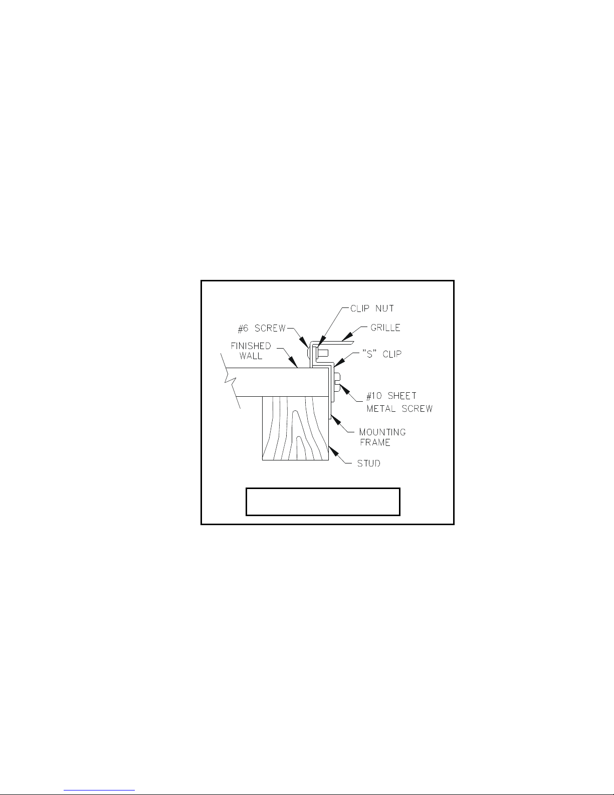
STEP 1: Provide wall opening as detailed in Installation Drawing. Frame must be positioned
such that frame flanges overlap and butt against finished wall surface. Mounting holes
are provided for #6 sheet metal screws. After frame is positioned in wall, swing chiller
support tray into position (See Installation Drawing), align tray holes with holes in frame
and fasten with #10 sheet metal screws. Mounted frame must support 50 pound chiller
in addition to fountain weight and user generated forces.
STEP 2: Install waste, supply and electrical lines in locations shown in Installation Drawing.
Waste and supply lines may be installed for either rear or side entry. Verify proper
waste, supply, electrical and frame locations. Use level to verify horizontal and vertical
frame mounting to insure proper bowl drainage.
STEP 3: Installation Drawing shows fountain bowls, back panel and grille locations. Unpack
bowls and remove bottom plate using 3/32” hex allen wrench. Install back panel on
frame with narrower edge to bottom. Position nut retainers into mounting frame and use
two 5/16-18x1 hex head screws partially started in outside holes to support panel.
Install bowl/bracket assembly onto panel using eight 5/16-18x1 hex head screws hand
tightened. See sheet 2 of Installation Drawing for appropriate bowl mounting pattern to
use for this model.
STEP 4: Remove 1-1/2” IPS outlet elbow from traps (not supplied). Install elbow inside frame
onto waste stub-outs. Reassemble trap “U” bends with inlets centered behind fountains.
STEP 5: Remove slip joint nuts from bottom of fountain waste outlets. Assemble nut over 1-1/4
O.D. end of longer waste elbow as supplied by Haws. Assemble waste elbows onto
bowl waste body using seal washer provided and tighten nut hand tight. Measure
vertical distance down to trap inlets and cut the vertical elbow (not supplied) to length
allowing 1/2” minimum for engagement into trap. Mark and similarly cut to length the
horizontal waste elbow. Install elbows and tighten slip joint nuts.