Using High Le vel Connections (see Diagram 1)
On the rear of your subwoofer cabinet is a block designated “HIGH LEVEL”. This block
contains four pairs of speaker terminals; one pair is designated as “input”and should be
connected to your amp/receiver, while the other pair is designated “output” for connection
to your main speakers. Each pair of terminals are designated left/right and color coded
black/red.
REMEMBER: Always connect red-to-red and black-to-black when making the
connections between amp/receiver to subwoofer, and from subwoofer to main/satellite
speakers. If you accidently reverse one of the connections (ie.red-to-black),you will
notice a lack of bass from your subwoofer, and/or the acoustic “image” from the main
speakers will be poorly defined.
Start by connecting the right speaker output of your amplifier or receiver to the right (R)
“input”of the subwoofer. Conversely, connect the left speaker output of your amp/
receiver to the left (L) “input”of the subwoofer.Next,connect the right (R) “output”of
the subwoofer to your right main speaker. Finally, connect the (L) “output” of the sub-
woofer to your left main speaker.
Using Low Le vel Connections (see Diagram 2, 3 & 4)
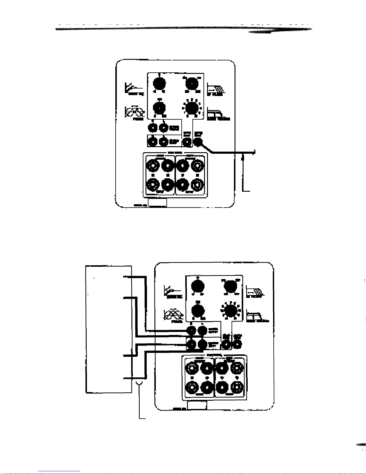
Using the “Subwoofer Output” of an A/V Receiver
or Processor (See Diagram2)
This method uses a single RCA-to-RCA interconnect cable to connect the “SUB-
WOOFER OUTPUT”jack from your A/V receiver or processor to the “SUBINPUT”on
the rear panel of the subwoofer.This method does not remove low frequencies from
your main speakers,and they will continue to reproduce bass frequencies.
Using External Crosso ver (See Diagram 3)
This method uses a single RCA-to-RCA interconnect cable to connect the
“SUBWOOFEROUTPUT” jack from an external crossover, such as the Mirage LFX two
channel crossover, to the “XOVER INPUT”of your subwoofer. This method by-passes all
of the subwoofer’s controls. Thus,all subwoofer functions are controlled by the external
crossover. (See External Crossover Owner’s Manual for more detail)
Using an A/V Receiver with PRE-OUT and
MAIN-IN RCA Jacks (for BPS-150i ONLY) (See Diagram 4)
This method uses four standard RCA-to-RCA interconnect cables. First,connect the
receiver’s left “PRE-OUT”to the jack marked left (L) “LOWLEVELINPUT”on the
subwoofer’s rear panel. Second,connect the receiver’s right “PRE-OUT”to the jack
marked right (R) “LOWLEVELINPUT”. Next,connect the left (L) “LOWLEVEL
OUTPUT”from the subwoofer’s rear panel to your receiver’s“LEFTMAIN INPUT”.
Finally, connect the right “LOW LEVELOUTPUT”to your receiver’s “RIGHT
MAIN INPUT”.