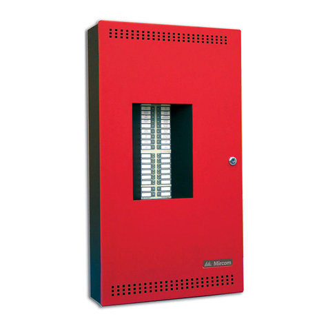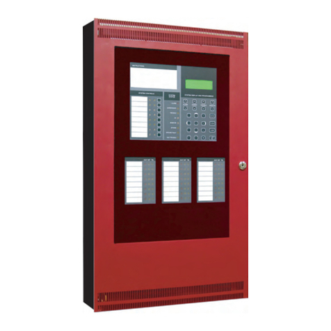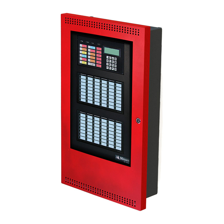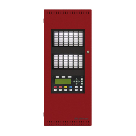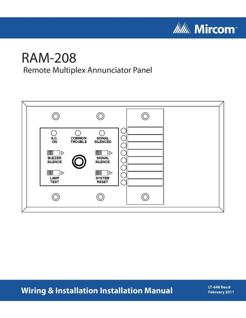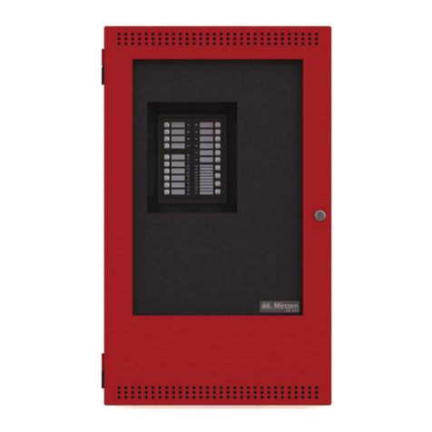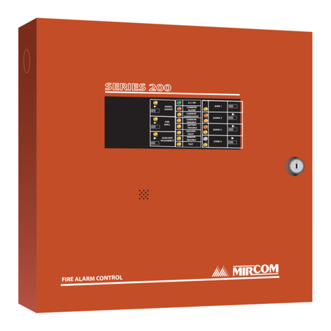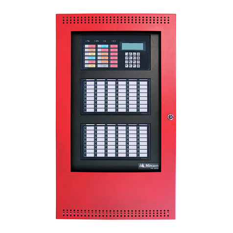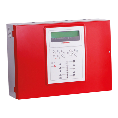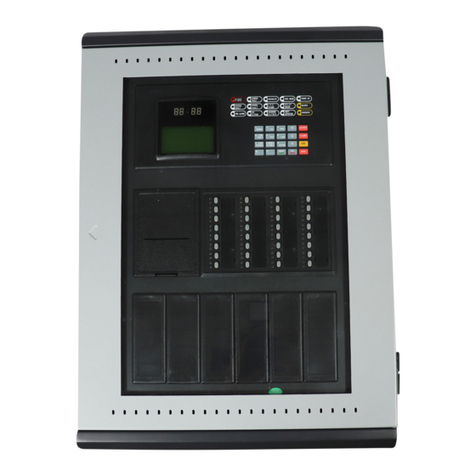
FA-1000 Series Installation and Operation Manual
i
Contents
Introduction ............................................................................................................................. 1
About this Manual ................................................................................................................ 1
About the FA-1000 ............................................................................................................... 1
Contact Us ........................................................................................................................... 2
System Components............................................................................................................... 3
Chassis ................................................................................................................................ 3
Circuit Adder Modules.......................................................................................................... 3
Auxiliary Models ................................................................................................................... 3
Enclosures ........................................................................................................................... 4
Flush Trim Rings .................................................................................................................. 4
Batteries ............................................................................................................................... 4
Remote Annunciators........................................................................................................... 4
FA-1000 Fire Alarm Control Panel Kits ................................................................................ 5
FA-1000 Accessories ........................................................................................................... 5
Maximum Number of Circuit Adder Modules that may be Installed ..................................... 5
Mechanical Installation and Dimensions .............................................................................. 6
Main Chassis Installation ..................................................................................................... 8
Main and Expander Chassis Installation .............................................................................. 9
Module Mounting Locations................................................................................................... 10
Module Settings....................................................................................................................... 13
Field Wiring.............................................................................................................................. 21
Main Fire Alarm Module Terminal Connections ................................................................... 21
Detection Module (DM-1008A) Terminal Connections......................................................... 23
Signal Module (SGM-1004A) Terminal Connections ........................................................... 24
Relay Module (RM-1008A) Terminal Connections............................................................... 25
UDACT-300A Main Board Terminal Connections................................................................ 26
Polarity Reversal and City Tie Module (Model PR-300) Terminal Connections................... 27
Power Supply Connections .................................................................................................. 28
Wiring Tables and Information ............................................................................................. 29
System Checkout .................................................................................................................... 30
Before Turning the Power On .............................................................................................. 30
Power-Up Procedure............................................................................................................ 30
Troubleshooting ................................................................................................................... 31
Indicators, Controls, and Operation ...................................................................................... 32
Common Indicators .............................................................................................................. 33
Common Controls ................................................................................................................ 34
Circuit Status Indicators ....................................................................................................... 35
Circuit (Zone) Disconnect Switches ..................................................................................... 36
Single Stage Operation ........................................................................................................ 37
Two Stage Operation ........................................................................................................... 37
Circuit Types ........................................................................................................................ 38
System Configuration ............................................................................................................. 40
Introduction to Configuration ................................................................................................ 40
Entering Configuration Mode ............................................................................................... 42
Exiting Configuration Mode .................................................................................................. 42
Factory Default Configuration .............................................................................................. 43
Restore to Default/Resize (Class A or B)............................................................................. 43
Resize System (Set Circuit Adder Module Number and Type) ............................................ 44
Configuration Features......................................................................................................... 44
