manuals.online logo
Brands
  1. Home
  2. •
  3. Brands
  4. •
  5. Mircom
  6. •
  7. Control Unit
  8. •
  9. Mircom MIX-M500MAP User manual

Mircom MIX-M500MAP User manual

MIX-M500MAP Monitor Module
INSTALLATION AND MAINTENANCE INSTRUCTIONS
BEfORE INSTALLINg
This information is included as a quick reference installation guide. Refer to
the control panel installation manual for detailed system information. If the
modules will be installed in an existing operational system, inform the opera-
tor and local authority that the system will be temporarily out of service. Dis-
connect power to the control panel before installing the modules.
NOTICE: This manual should be left with the owner/user of this equipment.
gENERAL DESCRIPTION
The MIX-M500MAP Monitor Module is intended for use in intelligent, two-
wire systems, where the individual address of each module is selected using
the built-in rotary decade switches. It provides either a 2-wire or 4-wire fault
tolerant initiating circuit for normally open contact fire alarm, supervisory, or
security devices. The module has a panel controlled LED indicator.
COMPATIBILITy REqUIREMENTS
To ensure proper operation, these modules shall be connected to listed com-
patible system control panels only.
fIgURE 1. CONTROLS AND INDICATORS:
C0917-01
SPECIfICATIONS
Normal Operating Voltage: 15 to 32 VDC
Maximum Alarm Current (LED on): 5.0mA (LED on)
Average Operating Current: 400 μA, 1 communication every 5 seconds, 47k EOL
EOL Resistance: 47K Ohms
Maximum IDC wiring resistance: 40 Ohms
Maximum IDC Voltage: 11 Volts
Maximum IDC Current: 400µA
Temperature Range: 32˚F to 120˚F (0˚C to 49˚C)
Humidity: 10% to 93% Non-condensing
Dimensions: 41/2˝ H x 4˝ W x 11/4˝ D (Mounts to a 4˝ square by 21/8˝ deep box.)
Accessories: SMB500 Electrical Box
MOUNTINg
The MIX-M500MAP mounts directly to 4-inch square electrical boxes (see
Figure 2). The box must have a minimum depth of 21/8inches. Surface
mounted electrical boxes (SMB500) are available from System Sensor.
fIgURE 2. MODULE MOUNTINg:
ISOLATED
QUADRANT
C1044-00
WIRINg
NOTE: All wiring must conform to applicable local codes, ordinances, and
regulations. This module is intended for power limited wiring only.
1. Install module wiring in accordance with the job drawings and appropri-
ate wiring diagrams.
2. Set the address on the module per job drawings.
3. Secure module to electrical box (supplied by installer), as shown in Fig-
ure 2.
25 Interchange Way, Vaughan Ontario, L4K 5W3
Phone: 905.660.4655; Fax: 905.660.4113
MC-460-008 1 I56-3314-000
©2008 Mircom
firealarmresources.com
MC-460-008 2 I56-3314-000
©2008 Mircom
fIgURE 3. TyPICAL 2-WIRE INITIATINg CIRCUIT CONfIgURATION, NfPA STyLE B:
(+)
(–)
(+)
(–)
(+)
(–)
MONITOR
MODULE
ANY NUMBER OF UL LISTED
CONTACT CLOSURE DEVICES
MAY BE USED. DO NOT MIX FIRE
ALARM INITIATING,
SUPERVISORY, OR SECURITY
DEVICES ON THE SAME MODULE.
TO NEXT
DEVICE
FROM PANEL OR
PREVIOUS DEVICE
47K EOL
RESIST
OR
ELR-47K
CONNECT MODULES TO LISTED
COMPATIBLE CONTROL PANELS ONLY
SIGNAL LINE CIRCUIT (SLC)
32 VDC MAX.
TWISTED PAIR
IS RECOMMENDED
ALL WIRING SHOWN IS SUPERVISED AND POWER LIMITED
INITIATING DEVICE CIRCUIT (IDC) - NFPA STYLE B
POWER LIMITED: 400µA MAX. @ 11 VDC MAX
INSTALL CONTACT CLOSURE DEVICES PER
MANUFACTURER’S INSTALLATION INSTRUCTIONS.
C1051-00
fIgURE 4. TyPICAL 4-WIRE fAULT TOLERANT INITIATINg CIRCUIT CONfIgURATION, NfPA STyLE D:
(+)
(-)
(+)
(–)
(+)
(–)
MONITOR
MODULE
TO NEXT
DEVICE
FROM PANEL OR
PREVIOUS DEVICE
CONNECT MODULES TO LISTED
COMPATIBLE CONTROL PANELS ONLY
SIGNAL LINE CIRCUIT (SLC)
32 VDC MAX.
TWISTED PAIR
IS RECOMMENDED
ALL WIRING SHOWN IS SUPERVISED AND POWER LIMITED
ANY NUMBER OF UL LISTED
CONTACT CLOSURE DEVICES
MAY BE USED. DO NOT MIX FIRE
ALARM INITIATING,
SUPERVISORY, OR SECURITY
DEVICES ON THE SAME MODULE.
INSTALL CONTACT CLOSURE DEVICES PER
MANUFACTURER’S INSTALLATION INSTRUCTIONS.
EOL RESISTOR
IS INTERNAL AT
TERMINALS
8 AND 9
C0919-03
firealarmresources.com

Other Mircom Control Unit manuals

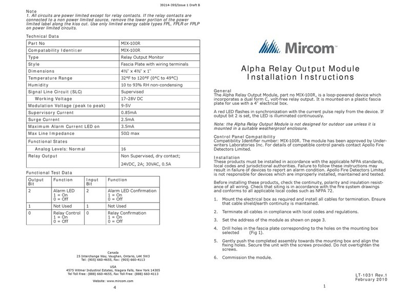
Mircom MIX-100R User manual

Mircom

Mircom MIX-100R User manual

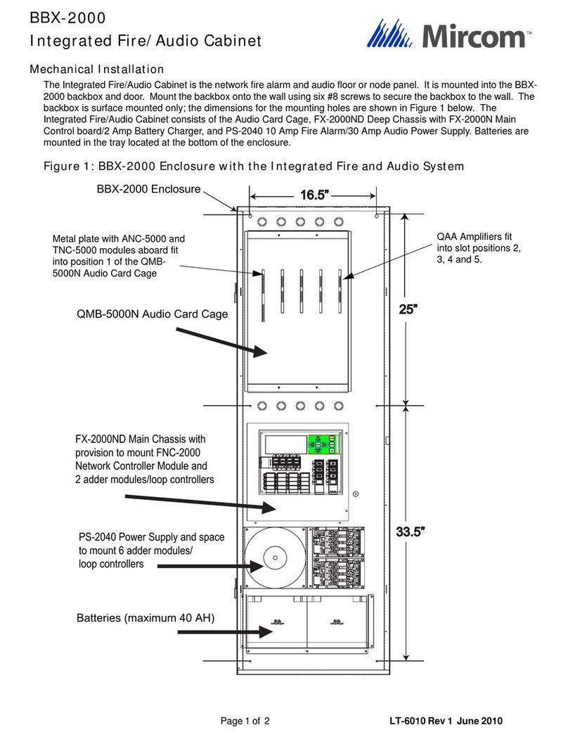
Mircom BBX-2000 User manual

Mircom

Mircom BBX-2000 User manual

Mircom QMP-5100AX User manual

Mircom

Mircom QMP-5100AX User manual

Mircom QDV-1000 User manual

Mircom

Mircom QDV-1000 User manual

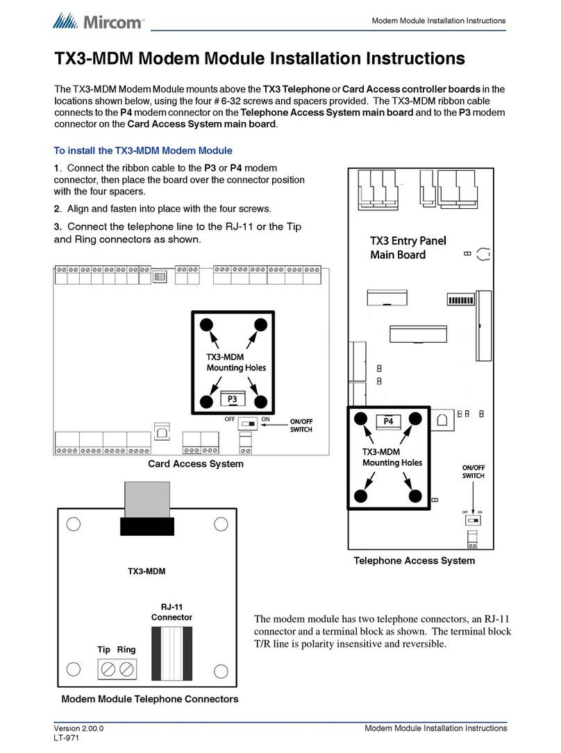
Mircom TX3-MDM User manual

Mircom

Mircom TX3-MDM User manual

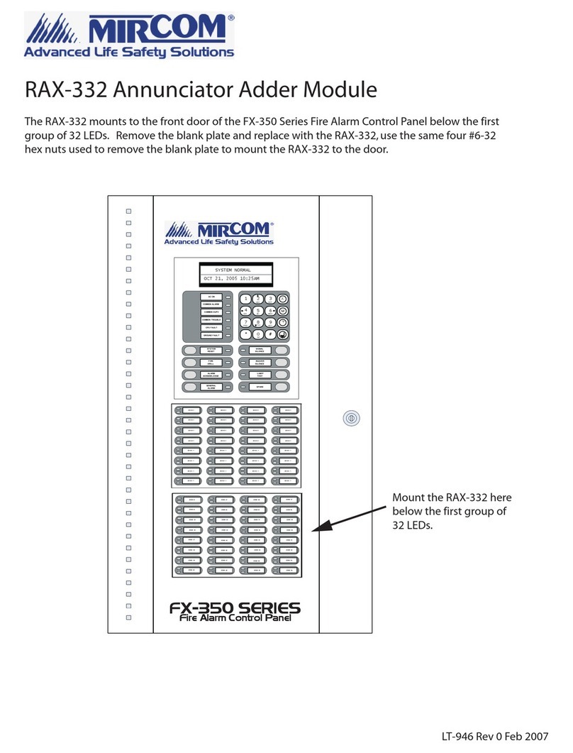
Mircom RAX-332 User manual

Mircom

Mircom RAX-332 User manual

Mircom RB-MD-750 User manual

Mircom

Mircom RB-MD-750 User manual

Mircom RB-MD-950 Guide

Mircom

Mircom RB-MD-950 Guide

Mircom QIF-2011 User manual

Mircom

Mircom QIF-2011 User manual

Mircom RB-MD-1113 User manual

Mircom

Mircom RB-MD-1113 User manual

Popular Control Unit manuals by other brands

Wisenet SPA-D1000 quick guide

Wisenet

Wisenet SPA-D1000 quick guide

Walther Systemtechnik SMS-05 Assembly instructions

Walther Systemtechnik

Walther Systemtechnik SMS-05 Assembly instructions

FAAC E124 quick start guide

FAAC

FAAC E124 quick start guide

Bender RFID117-L1 manual

Bender

Bender RFID117-L1 manual

SMC Networks VQ100 Series manual

SMC Networks

SMC Networks VQ100 Series manual

Pignology Piglet quick start

Pignology

Pignology Piglet quick start

Tyco Narvik-Yarway 51 Installation and maintenance instructions

Tyco

Tyco Narvik-Yarway 51 Installation and maintenance instructions

Armstrong Delta2 FLY Series Installation and operation manual

Armstrong

Armstrong Delta2 FLY Series Installation and operation manual

ABL 1V0002 quick start guide

ABL

ABL 1V0002 quick start guide

Banner DX99N9X1S2N0M2X0D2 manual

Banner

Banner DX99N9X1S2N0M2X0D2 manual

MPS MPM3695-25 user guide

MPS

MPS MPM3695-25 user guide

Edwards HemoSphere ClearSight HEMCSM10 manual

Edwards

Edwards HemoSphere ClearSight HEMCSM10 manual

Malekko AD/LFO manual

Malekko

Malekko AD/LFO manual

AutoConnect AC100GPS3G Quick install guide

AutoConnect

AutoConnect AC100GPS3G Quick install guide

Viessmann 5569 Operation manual

Viessmann

Viessmann 5569 Operation manual

aevit VIC 2.0 Installation & operation manual

aevit

aevit VIC 2.0 Installation & operation manual

Connect Tech Orbitty Carrier user guide

Connect Tech

Connect Tech Orbitty Carrier user guide

Dantel B11-48001-01 Installation & operation manual

Dantel

Dantel B11-48001-01 Installation & operation manual

manuals.online logo
manuals.online logoBrands
  • About & Mission
  • Contact us
  • Privacy Policy
  • Terms and Conditions

Copyright 2025 Manuals.Online. All Rights Reserved.