Mircom TX3 Series Manual

TX3 Telephone Access Installation Quick Reference
Version 2.2
Telephone Access System Configuration Quick Reference
for more information read the LT-969 Telephone Access System Manual
LT-9229 available on CD, USB flash drive, or
WWW.MIRCOM.COM
Clearing Event Logs
For the initial installation ensure that event logs are cleared. To clear event logs start from the Operation menu and
follow the steps below.
1. In the Operation menu Scroll DOWN to “2 Delete logs” and press ENTER .
2. In the Delete Logs menu Scroll DOWN to “3 All Log(s)” and press ENTER .
3. When you see “Del All Log(s)? Y” press ENTER again to confirm deletion. Press to go back.
Setting the Date and Time
To set the date and time start from the Operation menu and follow the steps below.
1. In the Operation menu Scroll DOWN to “3 Set time & date” and press ENTER .
2. Change the month using the Scroll UP and Scroll DOWN buttons. Use the Scroll LEFT and
Scroll RIGHT buttons to move on to the next portion of the date once the month has been set.
3. Repeat the previous step to set the day, year, hour, minute and AM or PM.
4. Press ENTER to confirm that the date and time have been set correctly. Press to go back.
Line Types
The TX3 can connect to five different telephone lines. To configure each telephone line as either an autodialer
controller (ADC), a no subscriber line (NSL), or not used, enter the Configuration menu and follow these steps.
1. In the Configuration menu ensure that “1 System Option” is highlighted and press ENTER .
2. Scroll DOWN to “2 Line Type” and press ENTER .
3. In the Line Type menu Scroll DOWN and Scroll UP then press ENTER to choose the line that
requires configuring. By factory default “L-1 Type” is set to “ADC” and the rest are set to “not used”.
4. Navigate through the line type options by using Scroll DOWN and Scroll UP and select the
appropriate line type (“ADC”, “NSL” or “not used”) by pressing or . Press ENTER to confirm
your selection and to return to the previous menu. From here you can select a different line to set its type. Press
to go back.
Main and Auxiliary Door DTMF
The Main and Auxiliary Door Dual Tone Modulated Frequency (DTMF) or touch tone feature allows the resident to
use their telephone touch tone keypad to open the main or auxiliary door. To set this up start from the Configuration
menu and follow the steps below.
1. In the Configuration menu ensure that “1 System Option” is highlighted and press ENTER .
2. Scroll DOWN to “3 Main door DTMF” or “4 Aux door DTMF” and press ENTER .
3. The factory default for the main door is the “9” key, the default for the auxiliary door is the “6” key. Browse using
the Scroll UP and Scroll DOWN buttons to the desired key.
4. Once the desired key is highlighted press or to select it. Press ENTER to confirm your
selection and to return to the previous menu.
Press to go back.
Door Timers
The door timers define the length of time the main and auxiliary door releases stay unlocked. To set these timers
start from the Configuration menu and follow the steps below.
1. In the Configuration menu ensure that “1 System Option” is highlighted and press ENTER .
2. Scroll DOWN to either “5 Main door timer” or “6 Aux door timer” and press ENTER .
3. The factory default for door timers is 30 seconds, change to the desired number of seconds by using the Scroll
UP and Scroll DOWN buttons.
4. Press ENTER to confirm the selection and return to the previous menu. Press to go back.
Talk Timer
The talk timer defines the maximum length of time that a visitor speaks with a resident. To set this timer start from
the Configuration menu and follow the steps below.
1. In the Configuration menu ensure that “1 System Option” is highlighted and press ENTER .
2. Scroll DOWN to “7 Talk Timer” as and press ENTER .
3. The factory default for the talk timer is 60 seconds, change to the desired number of seconds by using the
Scroll UP and Scroll DOWN buttons.
4. Press ENTER to confirm the selection and return to the previous menu. Press to go back.
Speaker and Microphone Volume
The speaker and microphone volume settings determine how loud these devices are. The volume settings range
from a value of 1 to 15. To set the volume levels start from the Configuration menu and follow the steps below.
1. In the Configuration menu ensure that “1 System Option” is highlighted and press ENTER .
2. Scroll DOWN to “22 Speaker volume” or “23 Mic volume” and press ENTER .
3. The factory default for the speaker volume is 11, the default for the microphone volume is 5. You can change
each volume setting to the desired level by using the Scroll UP and Scroll DOWN buttons.
Press ENTER to confirm the selection and return to the previous menu. Press to go back.
*
#
*
#
Attention: Do not select the “4” key for either the main or auxiliary door. The “4” key is reserved to
refuse entry and disconnect the call.
Do not select the “2 key for either the main or auxiliary door. The “2” key is used to answer a
waiting call.
Ensure that the key used for the main door is different than the key used for the auxiliary
door.
*
#
!

TX3 Telephone Access Configuration Quick Reference TX3 Telephone Access Configuration Quick Reference
Version 2.2 Thank You for more information go to the CD, USB flash drive, or website and read the LT-969 Telephone Access System Manual
LT-9229
WWW.MIRCOM.COM
Add a New Record
From the Configuration screen follow these steps.
1. In the Configuration menu Scroll DOWN to “2 Database” and press ENTER .
2. In the Database menu ensure that “1 Add Record” in highlighted and press ENTER .
3. There will be 11 different screens that prompt for information in order to create a record. Each screen is listed in
order of appearance and explained in Table 1: List of Screens. Screens marked with an asterisk in the table
must be filled in. Use the keypad to input information and press ENTER to confirm your selection and
proceed to the next screen. Press to go back.
Determining Firmware Version
This quick start manual is written based on firmware version 1.4.0. To determine your firmware version follow these
steps.
1. From the Main Welcome Screen enter the Main Menu by inputting “9999”.
2. Scroll DOWN to “3 View Cfg Info”.
3. Press ENTER and Scroll DOWN to view the firmware version. Press to go back.
Entering the Configuration or Operation Menus
To enter the system Configuration or Operation menus follow these steps.
1. From the Main Welcome Screen enter the Main Menu by inputting “9999”.
2. Press ENTER when the option “1 Configuration” appears or Scroll DOWN to “2 Operation” then
press ENTER .
3. Input the passcode and press ENTER , the factory default is “3333”. Press to go back.
Defaulting Configuration
For the initial installation ensure that all settings are factory defaults by entering the Configuration menu and
following these steps.
1. In the Configuration menu Scroll DOWN to “5 Factory Dflt” and press ENTER .
2. When you see “Reset to default? Y” press ENTER to default all settings. Press to go back.
Delete all Records
For the initial installation ensure that there are no pre-existing records by deleting all records. Starting from the
Configuration screen follow these steps.
1. In the Configuration menu Scroll DOWN to “2 Database” and press ENTER .
2. In the Database menu Scroll DOWN to “7 Delete all rec” and press ENTER .
3. When you see “Delete all Record?Y” press ENTER again to confirm deletion. Press to go back.
Order of
Appearance
Database Menu Display Explanation/Description
1Enter Apt#
[________] Enter the resident’s apartment number (up to 8 digits).
2* Enter Dial Code
[____] Enter the resident’s 4 digit dial code. If all digits are not required put in leading zeros.
3Main Door sec. code
[____]
Enter up to 4 digits from 0 to 9 to replace the main door DTMF key for the specific
resident. To open the Main Door, the resident enters the Main Door Security code
followed by the # key. Do not select “4” or “2”.
4Aux Door sec. code
[____]
Enter up to 4 digits from 0 to 9 to replace the auxiliary door DTMF key for the specific
resident. To open the Auxiliary Door, the resident enters the Auxiliary Door Security
code followed by the # key. Do not select “4” or “2”.
5* Enter Resident Name
[_______________]
Enter the resident’s name. The name must be unique and a maximum of 15
characters. See the figure titled “Entering Information”.
6*
Line in Use
[x] Line 1
...
[ ] Line 5
Enter the speech path for resident to communicate to the ADC line or to a relay
control unit. Line 1 is default. Scroll through using the arrow keys and make a
selection using the star or pound key.
7* (NSL Only) Enter Relay Code
[____]
Enter the resident’s assigned 4 digit relay code. Relay codes start at 1 for the first
relay, up to 1535.
7* (ADC Only) Enter Phone Number
[__________________]
Enter the resident’s telephone number (up to 18 digits including commas or semi-
colons that represent pauses). Use the up arrow key for a comma (1 second pause)
and the down arrow key for a semi-colon (3 second pause).
8Enter Keyless Code
[______]
Enter the assigned keyless code (up to 6 digits). Each keyless code must be unique.
Input “0” if keyless entry is not to be used for the resident.
9
Keyless Code Corr
[x] Main door relay
[ ] Aux door relay
Select which door (main, auxiliary or both) can be opened by the resident using a
keyless code. Scroll through using the arrow keys and make a selection using the
star or pound key.
10 Enter Elev Rest Addr
[__]
Enter the ID (or address) of the Elevator Restriction controller for the resident.
Accepts values between 1 and 31.
11 Enter Elev Rest Code
[__]
Enter the elevator restriction relay number for the resident. Accepts values between
1 and 96.
12
Hide Display
[ ] Hide
[x] Display
This feature turns the resident information display on or off. When off the resident’s
information is only displayed in configuration mode. Scroll through using the arrow
keys and make a selection using the star or pound key. Default is set to display
resident information.
13
Ring Pattern
[x] Ring Pattern 1
...
[ ] Ring Pattern 5
Enter the ring pattern for the resident. Scroll through using the arrow keys and make
a selection using the star or pound key. The default ring pattern is Ring Pattern 1.
Ring patterns are only used by NSL systems.
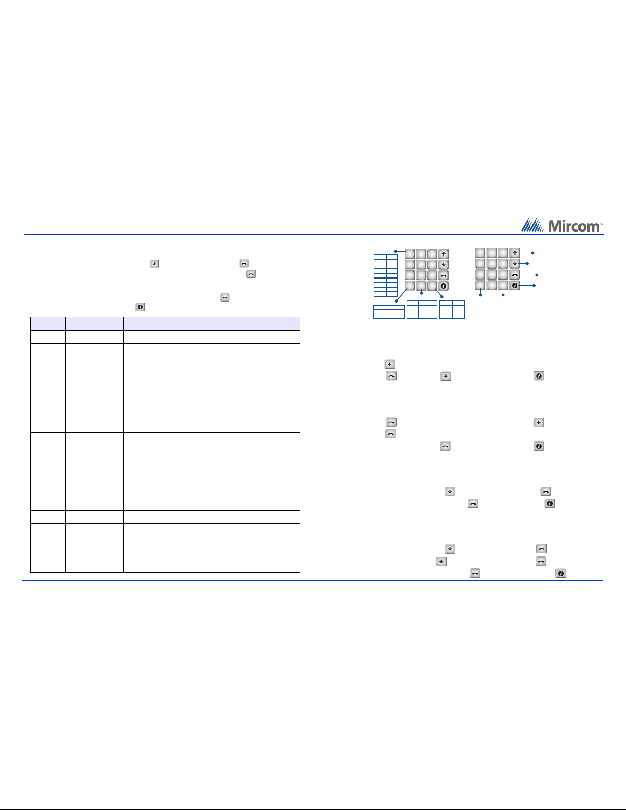
Scroll UP
2
ABC
3
DEF
1
5
JKL
6
MNO
4
GHI
8
TUV
9
WXYZ
7
PQRS
0
*
#
Scroll DOWN
ENTER
CANCEL
Scroll LEFT Scroll RIGHT
NAVIGATING MENUS
ENTERING INFORMATION
2
ABC
3
DEF
1
5
JKL
6
MNO
4
GHI
8
TUV
9
WXYZ
7
PQRS
0
*
#
“1” KEY
PRESS
once ,
twice -
3 times (
4 times )
5 times /
6 times &
“*” KEY
PRESS
once moves
cursor left
“#” KEY
PRESS
once moves
cursor
right
“0“ KEY
PRESS
once deletes
character
twice space
9 times *
10 times 1
Other manuals for TX3 Series
29
Other Mircom Telephone manuals