Misonix SonaStar SYSTEM-M300-0 Series User manual

InstructionsForUse
Models with serial #’s that begin with FHF
SYSTEM-M300
SYSTEM-M360
SYSTEM-M380

IFU-607 Rev D P age 1of 65

IFU-607 Rev D P age 2of 65
Table of Contents
1. General Safety Statements ........................................................................................................................................................................ 3
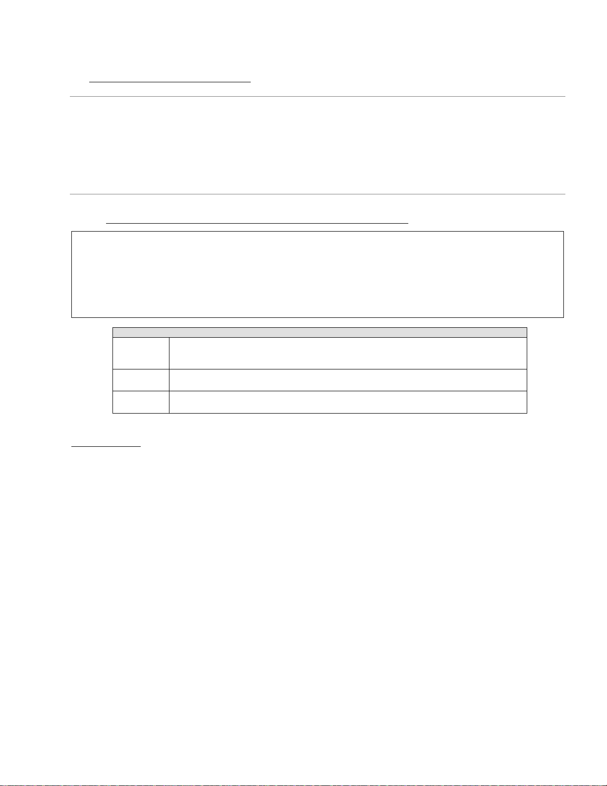
1.1. Summary of Safety Notices: Warnings, Cautions and Notes.............................................................................................................................3
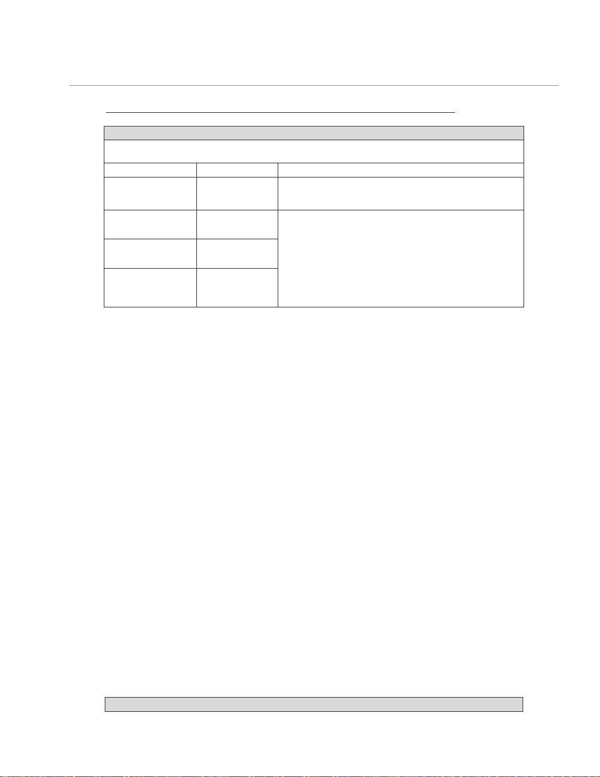
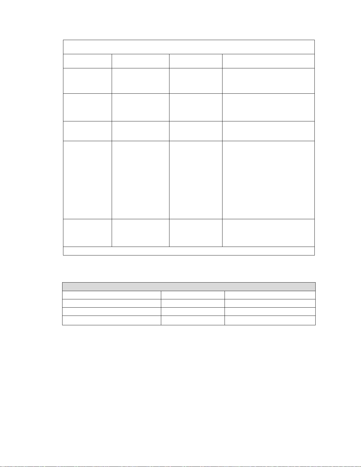
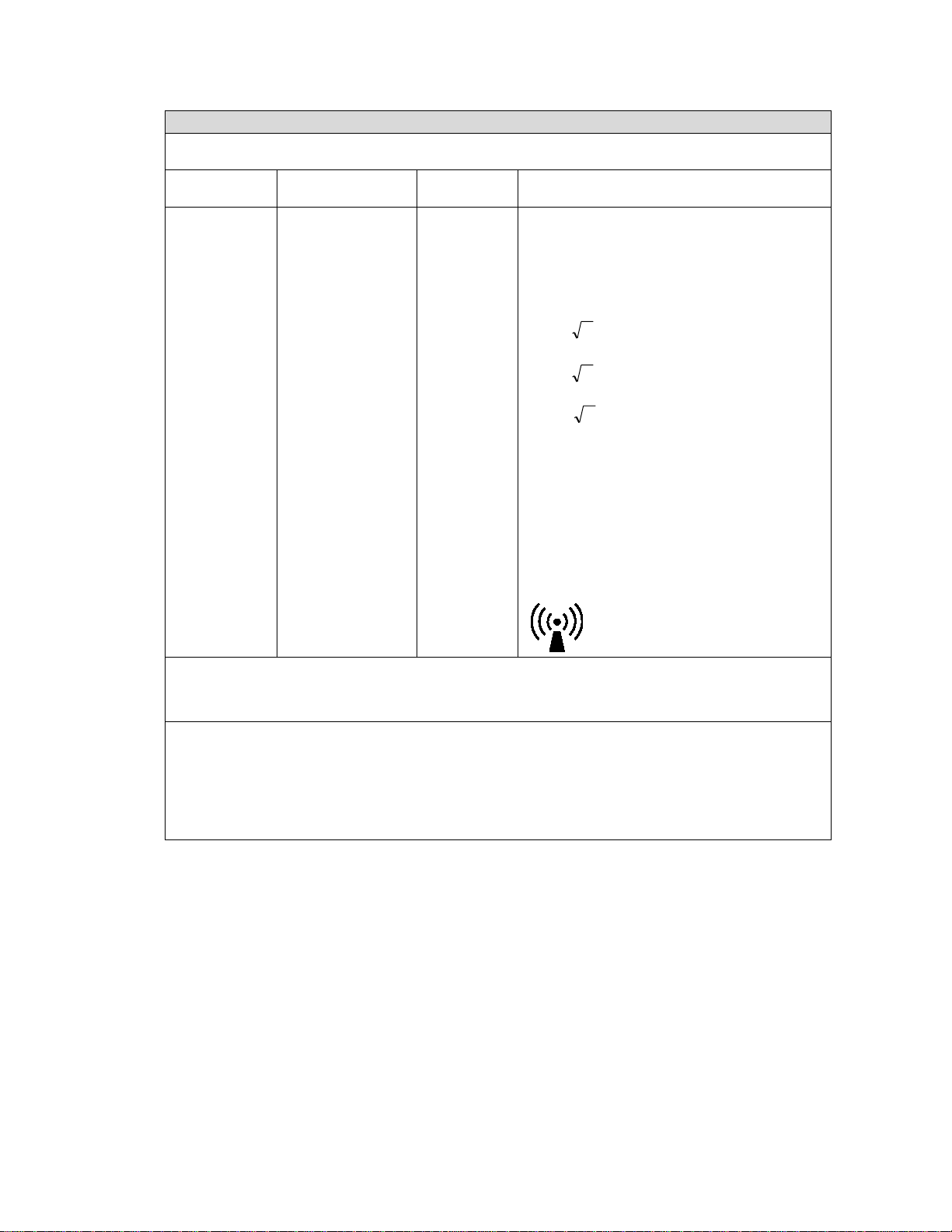
1.2. EMC Statement ...................................................................................................................................................................................................6
1.3 Electrical Safety Statement .............................................................................................................................................................................10
1.4 Environmental Statement.................................................................................................................................................................................10
1.5 FCC Statement.................................................................................................................................................................................................... 11
1.6 Trademark Information..................................................................................................................................................................................... 11
1.7 Explanation Of Symbols .....................................................................................................................................................................................12
2. Indications And Contraindications............................................................................................................................................................ 14
2.1. Indications..........................................................................................................................................................................................................14
2.2. Contraindications ..............................................................................................................................................................................................14
3. Adverse Effects........................................................................................................................................................................................ 14
4. Principle of Operation ...............................................................................................................................................................................15
4.1. Ultrasonic Theory ..............................................................................................................................................................................................15
4.2. System Overview...............................................................................................................................................................................................15
4.3. Reusable System Components .........................................................................................................................................................................18
4.4. Single-use, Sterile Components........................................................................................................................................................................19
4.5. Optional Accessories for Monopolar COAG .....................................................................................................................................................20
5. Console - Receptacles, Controls and Indicators..........................................................................................................................................20
5.1. Side Panel Receptacles......................................................................................................................................................................................20
5.2 Front Panel Controls..........................................................................................................................................................................................21
5.3 Rear Controls, Labeling, Storage and Receptacles ..........................................................................................................................................24
5.4 Wireless System Receptacles, Controls and Indicators....................................................................................................................................27
6. System Set-up ..........................................................................................................................................................................................31
6.1. Installation ......................................................................................................................................................................................................... 31
6.3 Console Set-up –Part I (In the Non-Sterile Field).............................................................................................................................................32
6.4 Handpiece Assembly ..........................................................................................................................................................................................32
6.5 Console Set-up –Part II (In the Non-Sterile Field)............................................................................................................................................35
6.6 Perform System Check......................................................................................................................................................................................36
6.7 Operative Use of System................................................................................................................................................................................... 37
6.8 Post-Operative Procedure ................................................................................................................................................................................38
7. Handpiece Assembly and Disassembly ..................................................................................................................................................... 39
7.1. Items Required for Handpiece Assembly..........................................................................................................................................................39
7.2. Handpiece Inspection ........................................................................................................................................................................................39
7.3. Handpiece Assembly –Curved Extended Handpiece (CE)...............................................................................................................................40
7.4. Electrosurgery Connector Assembly ................................................................................................................................................................41
7.5. Handpiece Disassembly –Short Straight Handpiece (SS) ...............................................................................................................................42
7.6. Handpiece Disassembly –Curved Extended Handpiece (CE) ..........................................................................................................................42
8. Monopolar COAG Guidelines.................................................................................................................................................................... 44
8.1. Background........................................................................................................................................................................................................44
8.2. Preparing the System for Monopolar COAG Use .............................................................................................................................................45
8.3. Using Monopolar COAG with the SonaStar System ........................................................................................................................................46
9. Cleaning, Sterilization and Maintenance .................................................................................................................................................. 48
9.1. Disassembly.......................................................................................................................................................................................................48
9.2. Cleaning .............................................................................................................................................................................................................48
9.3. Sterilization of Reusable Sterile Field Components .........................................................................................................................................51
9.3.1 For Handpiece Disassembled.............................................................................................................................................................................51
9.4. Deviations from Decontamination, Cleaning And Sterilization Instructions ..................................................................................................52
9.5. Moving the Unit .................................................................................................................................................................................................53
9.6 Periodic Maintenance........................................................................................................................................................................................53
10. Troubleshooting .......................................................................................................................................................................................55
10.1. Possible Malfunctions Not Associated with an Error Code.………………… ………………………………..……………………….…….55
10.2. Error Code Messages......................................................................................................................................................................................... 57
10.3. Clearing Faults.................................................................................................................................................................................................... 57
10.4. Overriding faults................................................................................................................................................................................................58
11. Specifications .......................................................................................................................................................................................... 59
12. Service, Repair and Technical Correspondence ......................................................................................................................................... 61
12.1. Fuse Requirements............................................................................................................................................................................................61
12.2. Repair, Service and Replacement Parts............................................................................................................................................................63
12.3. Important Notice ...............................................................................................................................................................................................63

IFU-607 Rev D P age 3of 65
1. General Safety Statements
WARNING 1.1 The SonaStar system is an electro-mechanical device, which under certain circumstances, could present an electrical shock hazard
to the operator and/or patient. Please read manual thoroughly and follow directions stated herein to ensure maximum safety
during operation. This manual shall be kept in close proximity to the system for easy referral when needed.
WARNING 1.2 The SonaStar system is intended to be used in various types of invasive, surgical procedures. There may be indirect danger to the
patient should the device fail during the procedure. It is recommended that the facility follows its back-up equipment protocols.
CAUTION 1.1 Federal law restricts this device to be sold only to or on the order of a licensed healthcare practitioner.
1.1. Summary of Safety Notices: Warnings, Cautions and Notes
Please read this section of the manual carefully. It contains a summary of all precaution, warning and caution
statements contained in the manual. However, the user is advised to read the entire manual and operate the device
only in accordance with all of the instructions contained herein.
Servicing of this device should only be performed by qualified technicians authorized by Misonix, Inc. There are no
service controls accessible to the user.
Conventions on Warnings, Cautions and Notes
WARNING
Denotes potentially dangerous situation that could result in death or serious injury to patient, operator or
staff.
CAUTION
Denotes potentially dangerous situation that could result in moderate injury to patient, operator or staff.
NOTE
Indicates potential hazard that may result in product damage.
Table 1.1 Conventions on warnings, cautions and notes
List of Warnings
WARNING 1.1 The SonaStar system is an electro-mechanical device, which under certain circumstances, could present an electrical shock hazard
to the operator and/or patient. Please read manual thoroughly and follow directions stated herein to ensure maximum safety
during operation. This manual shall be kept in close proximity to the system for easy referral when needed.
WARNING 1.2 The SonaStar system is intended to be used in various types of invasive, surgical procedures. There may be indirect danger to the
patient should the device fail during the procedure. It is recommended that the facility follows its back-up equipment protocols.
WARNING 1.3 The SonaStar system generates high voltages within the console itself and the connected handpiece. To avoid injury, the console
should never be operated before ensuring that its cover is properly closed and not tampered with. Do not attempt to remove or
disassemble the cover. There are no user-serviceable parts inside the console. All service should only be performed by an
authorized Misonix representative. No modification of this equipment is required.
WARNING 1.4 Proper system grounding can only be ensured when an approved, hospital-grade receptacle and matching power cord are used.
To avoid the risk of electric shock, this equipment must only be connected to a supply with protective earth. Install plug and
receptacles as per local regulations before operating the unit. Power cord, plug and receptacle should be examined to verify that
they are in good working condition before connecting the console. Never pull on the power cord to remove it from the receptacle.
WARNING 1.5 Connecting the console to a power outlet with inadequate voltage or frequency may cause the unit to malfunction or to create a
shock or fire hazard. Confirm that the voltage selector switch on the console rear panel is set to the local voltage setting and ensure
that the correct fuses are being used. Refer to Section 12.1 on instructions for fuse replacement.
WARNING 1.6 Explosion Hazard: Never use the SonaStar system in the presence of a flammable or explosive atmosphere, such as flammable
anesthetics.
WARNING 6.1 Use only sterilization cycles specified in this user manual. Do not use any other sterilization cycles. Improper sterilization can lead
to handpiece or accessory damage, patient injury, or death.
WARNING 6.2 Improper connection of the handpiece cable may present a shock hazard. Confirm that handpiece connector is dry prior to plugging
it in.
WARNING 6.3 During system check, make sure the tip of the handpiece is free from contact with any object. Allowing contact with the tip may

IFU-607 Rev D P age 4of 65
result in damage and/or personal injury.
WARNING 6.4 Inadvertent or improper foot pedal depression can cause possible injury to the patient, surgeon, or operating room staff, and can
cause product damage. Place foot pedal where it is highly visible and labels can be clearly seen.
WARNING 6.5 Do not lay the handpiece on the patient when not in use. When not in use, keep the handpiece on a dry, non-conductive surface
with the tip free from contact with any objects.
WARNING 6.6 Make sure that the handpiece is properly positioned at the tissue site before the footswitch is depressed. Once the Preset or Linear
key has been chosen, any inadvertent activation of the footswitch will initiate vibration. DO NOT TOUCH tip while activated.
WARNING 6.7 Never activate Vibration or electrosurgery while using the cleaning stylet. Tip damage and operator, patient, or staff injury may
result.
WARNING 7.1 Improper assembly of Single-Use Monopolar Handpiece Cable to endcap can expose potentially dangerous electrosurgery voltage.
Always make sure the Single-Use Monopolar Handpiece Cable socket is firmly and fully engaged onto the pin in the endcap.
WARNING 7.2 Ensure that the aspiration tubing is fully seated onto the Aspiration Port in the base of handpiece.
WARNING 7.3 Remove all housing components, silicone elbow, silicone sleeve and ultrasonic tip from the handpiece prior to cleaning and/or
sterilization; otherwise proper cleaning/sterilization may be inhibited.
WARNING 8.1 Saline leakage through handpiece housing can cause a hazard when electrosurgery is energized. Always make sure the handpiece
housing parts are properly assembled, with mating parts firmly in contact.
WARNING 9.1 Single-use items should be discarded following each surgical procedure according to hospital protocol for disposal of bio
contaminated wastes. Do not attempt to reuse or re-sterilize any single-use items. Dispose of ultrasonic tips in a sharps
container.
WARNING 9.2 All reusable handpiece parts and accessories must be properly cleaned and sterilized before each use as per instructions contained
in this manual. Failure to do so may lead to infections, which can ultimately cause patient death.
WARNING 9.3 Misonix Inc. has validated all cleaning and sterilization cycles given in this manual. It is highly recommended that the procedures
given in this manual for cleaning and sterilizing the SonaStar System and related accessories be followed. It is the responsibility of
the user of this device or any accessories used with it to validate procedures for cleaning and/or sterilization if they differ from the
procedures as outlined in this manual.
WARNING 10.1 If a Mains Power fuse fails after replacement when the unit is reactivated, discontinue use of the device and contact an authorized
Misonix representative.
List of Cautions
CAUTION 1.1 Federal law restricts this device to be sold only to or on the order of a licensed healthcare practitioner.
CAUTION 1.2 This device is considered medical electrical equipment. Medical electrical equipment needs special precautions regarding
electromagnetic compatibility (EMC) and needs to be installed and put into service according to the EMC information provided in
this operator’s manual.
CAUTION 1.3 Portable and mobile RF communication equipment can affect medical electrical equipment. If RF equipment is in use, monitor the
SonaStar for proper function during procedure.
CAUTION 1.4 The use of accessories, transducers and cables other than those specified may result in increased emissions or decreased immunity
of the device. Use only Misonix branded equipment and accessories.
CAUTION 1.5 When used adjacent to other electrical equipment, the console should be observed to verify normal operation in the configuration
in which it will be used.
CAUTION 3.1 The SonaStar system and its accessories may emit harmful acoustic pressure if exposure exceeds recommended limits.
CAUTION 4.1 Never operate the handpiece without proper irrigation. Irreparable damage to the handpiece and probe may result if adequate
irrigation is not provided to the probe tip.
CAUTION 6.1 Adequate air circulation is needed to cool electronic components inside of the unit. Do not block the cooling fans located on the
lower console rear. Blocking these vents may cause unit to overheat and malfunction or create a shock hazard.
CAUTION 6.2 It is strongly advised that a sterile backup handpiece be readily available in the operating room as insurance against any
contamination or malfunction of the handpiece used during surgery.
CAUTION 6.3 All reusable system components like handpiece, torque wrench and torque fixture are supplied NON-STERILE. All items intended
for use in the sterile field must be cleaned and sterilized as per the indicated instructions before first clinical use and before every
subsequent clinical use.
CAUTION 6.4 The "Vacuum" port of the suction canister should contain a positive shut off float. The aspiration pump connection should be made
only to the VACUUM PORT to prevent overflow contamination.
CAUTION 6.5 All items intended for use in the sterile field must be cleaned and sterilized as per indicated instructions in Chapter 9 before each

IFU-607 Rev D P age 5of 65
clinical use.
CAUTION 6.6 The disposable items are intended for one procedure only (single use). Do not attempt to reuse or re-sterilize.
CAUTION 6.7 If COAG is to be performed, the Single-Use Monopolar Handpiece Cable must be introduced in the sterile field, because the cable
is supplied sterile, and is NOT AUTOCLAVABLE. DO NOT RE-STERILIZE THE SINGLE-USE MONOPOLAR HANDPIECE CABLE.
CAUTION 6.8 Aspiration tissue release valve and irrigation pump can create pinch points. Keep fingers away from these parts while operating
unit. Use caution when assembling components.
CAUTION 6.9 Incorrect routing of irrigation tubing will result in no flow of irrigating solution to the tip; this may cause damage to handpiece.
CAUTION 6.10 The system check should always be done in advance of preparing the patient for surgery to minimize risk to patient in case of
system malfunction.
CAUTION 6.11 Simultaneous use of a standard monopolar device with ultrasound can create sparking and possible tip damage.
CAUTION 6.12 Vibrating tip contact with hard objects can cause tip damage.
CAUTION 6.13 If a fault occurs, suspend operation of handpiece and unit. Determine the cause of the problem and its solution by consulting the
troubleshooting tables found on pages 59 and 60 of this manual.
CAUTION 6.14 Electrosurgery units approved for use with this unit are listed in Section 8.1. Any electrosurgery units used with this system should
be operated at settings lower than 70. Failure to maintain the electrosurgery signal at settings below 70W can induce permanent
system damage.
CAUTION 6.15 Use of a separate monopolar instrument at electrosurgery settings greater than 70 W while simultaneously touching the handpiece
probe to tissue can induce faults and possible system damage.
CAUTION 7.1 Be careful not to damage the tip when sliding the torque wrench over the tip. System failure may result from scratches or damage
to the tip when vibration is active.
CAUTION 7.2 Use only properly calibrated torque wrench. Send torque wrench to Misonix for calibration every twelve months.
CAUTION 9.1 Use manual cleaning techniques only. Do not use ultrasonic cleaners or automated washers to clean the handpiece as both
methods could damage handpiece.
CAUTION 9.2 Be certain to clear debris from all internal passages by brushing. Failure to do so may hinder sterilization of units during
autoclaving.
CAUTION 9.3 Do not immerse ultrasonic console, handpiece, irrigation pump, remote footswitch, IR receiver or electric cables. These items are
not sealed against liquids and damage to equipment will result.
CAUTION 10.1 Improper use or adjustment of this device may invalidate the Misonix, Inc. Warranty agreement. Contact your authorized Misonix,
Inc. representative before attempting to troubleshoot this device in any manner other than those specified in this manual. There
are no user serviceable parts.
CAUTION 12.1 The only user replaceable fuses are the two fuses located on the bottom rear of the unit and the one located on the top rear of the
unit. Replacement fuses must be identical in type, voltage rating and current rating to the original fuse.
CAUTION 12.2 Use only genuine replacement parts from Misonix. Use of parts furnished by other sources may result in patient or operator injury
or system malfunction and will void any applicable warranty.
CAUTION 12.3 When returning items, before using loose packing materials, such as foam pellets, shredded paper or similar, be sure to wrap the
component(s) separately in plastic bags, film or other protective wrapping.

IFU-607 Rev D P age 6of 65
List of Notes
List of Notes
NOTE 4.1 For proper operation, the console and wireless footswitch must have the same frequency code number. Refer to Section 5.4 for
more details.
NOTE 4.2 A second torque wrench is highly recommended to allow system usage during wrench calibration. See section 9.7 for more
information on wrench calibration.
NOTE 4.3 It is highly recommended to have backups of all single- use items available in case of unforeseen events.
NOTE 5.1 In addition to their normal function, the Preset or Linear keys can also be used to reset the unit after a fault condition has been
displayed and corrected (or overridden).
NOTE 5.2 When a footswitch function is activated, if the activation LED does not illuminate on the top of the console (see Figure 5.7, #2),
plug the Remote IR receiver into its receptacle at the console rear and place it within direct line of sight with the footswitch. The
Remote IR receiver can be moved closer to the wireless footswitch or linked directly to it to improve signal reception as needed.
NOTE 6.1 The SonaStar system should be fully tested and inspected prior to each procedure. The console, footswitch, handpieces, all cables
and accessories should be examined for proper appearance and condition.
NOTE 6.2 The IV pole should be positioned to yield continuous flow and visibility, but elevated IV bag position is not necessary to achieve
flow.
NOTE 6.3 The sterile wire stylet, torque wrench and torque fixture should be retained with the handpiece in the sterile field.
NOTE 6.4 The handpiece, torque wrench and torque fixture should be sterilized prior to starting assembly according to Method 2.
NOTE 6.5 When assembling aspiration tubing, be sure there are no kinks or blockages along the entire tubing’s length. Be sure the cuff end
of the aspiration tubing is not deformed at its connection to the patient port on the aspiration canister.
NOTE 6.6 If there is a high pitched squealing noise after pressing the Setup key, turn the power switch off and check that the tip is torqued
properly. If it was, there may not have been adequate irrigation fluid at the tip. Turn the unit back on and depress the flush pedal
again making certain there is irrigation at the tip, then press the Setup key.
NOTE 6.7 The tissue release valve should be checked for proper operation by activating Flush. If irrigation flow is immediately aspirated prior
to reaching the operative site, proper tubing routing and tissue release valve operation should be checked.
NOTE 7.1 Do not attempt to tighten or loosen handpiece components by holding the handpiece case. Always place the handpiece into the
torque fixture and use the torque wrench when tightening or un-tightening the tip. Do not over-tighten the tip.
NOTE 7.2 Monopolar Handpiece Cable is supplied sterile and is NOT sterilizable.
NOTE 8.1 The SonaStar system has been designed for use with monopolar COAG using a Misonix approved electrosurgical generator. CUT
mode has NOT been approved for use with the SonaStar. DO NOT use this mode with the SonaStar.
NOTE 8.2 Do not clean the tip with abrasive or metallic materials, as damage to the tip may result in device failure.
NOTE 9.1 Allow reusable, autoclavable items to gradually return to room temperature after steam sterilization and prior to usage.
NOTE 10.1 The following tables do not attempt to anticipate all possible failures. Any fault not listed in the tables must be referred to an
authorized Misonix, Inc. technical representative.
NOTE 12.1 The SonaStar is configured for a specific electrical input (line) at the factory before shipment, and is not intended to be configured
or changed in the field except by Misonix authorized technical personnel. The unit may only be used with the electrical input
originally intended.
1.2. EMC Statement
The SonaStar system is designed and tested to comply with FCC regulations for conducted and radiated emissions under
Part 18 Subchapter J. and to comply with IEC EN60601-1-2: 2007 guidelines for EMC.
CAUTION 1.2 This device is considered medical electrical equipment. Medical electrical equipment needs special precautions regarding
electromagnetic compatibility (EMC) and needs to be installed and put into service according to the EMC information provided in
this operator’s manual.
CAUTION 1.3 Portable and mobile RF communication equipment can affect medical electrical equipment. If RF equipment is in use, monitor the
SonaStar for proper function during procedure.
CAUTION 1.4 The use of accessories, transducers and cables other than those specified may result in increased emissions or decreased immunity
of the device. Use only Misonix branded equipment and accessories.
CAUTION 1.5 When used adjacent to other electrical equipment, the console should be observed to verify normal operation in the configuration

IFU-607 Rev D P age 7of 65
in which it will be used.
Electromagnetic Compatibility Guidance (in accordance with EN/IEC 60601-1-2:2007)
Guidance And Manufacturer’s Declaration – Electromagnetic Emissions (Table 201)
The SONASTAR SYSTEM is intended for use in the electromagnetic environment specified below. The customer or the user of
SONASTAR SYSTEM should ensure that it is used in such an environment.
Emissions test
Compliance
Electromagnetic environment –guidance
RF emissions
CISPR 11
Group 1
The SONASTAR SYSTEM uses RF energy only for its internal function.
Therefore, its RF emissions are very low and are not likely to cause any
interference in nearby electronic equipment.
RF emissions
CISPR 11
Class A
The SONASTAR SYSTEM is suitable for use in all establishments other
than domestic and those directly connected to the public low-voltage
power supply network that supplies buildings used for domestic purposes.
Harmonic emissions
IEC 61000-3-2
Class A
Voltage fluctuations/
flicker emissions
IEC 61000-3-3
Complies
Table 1.2 Guidance & manufacturer’s declaration on electromagnetic emissions (EN table 201)
Guidance And Manufacturer’s Declaration – Electromagnetic Immunity (Table 202)

IFU-607 Rev D P age 8of 65
The SONASTAR SYSTEM is intended for use in the electromagnetic environment specified below. The customer or the user of
the SONASTAR SYSTEM should assure that it is used in such an environment.
Immunity test
IEC 60601
test level
Compliance level
Electromagnetic environment –guidance
Electrostatic
discharge (ESD)
IEC 61000-4-2
o±6 kV contact
o±8 kV air
o±6 kV contact
o±8 kV air
Floors should be wood, concrete or ceramic
tile. If floors are covered with synthetic
material, the relative humidity should be at
least 30%.
Electrical fast
transient/burst
IEC 61000-4-4
o±2 kV for power supply
lines
o±1 kV for input/output
lines
o±2 kV for power
supply lines
o±1 kV for input/output
lines
Mains power quality should be that of a
typical commercial or hospital environment.
Surge
IEC 61000-4-5
o±1 kV differential mode
o±2 kV common mode
o±1 kV differential
mode
o±2 kV common mode
Mains power quality should be that of a
typical commercial or hospital environment.
Voltage dips, short
interruptions and
voltage variations on
power supply input
lines
IEC 61000-4-11
<5 % UT
(>95 % dip in UT)
for 0,5 cycle
40 % UT
(60 % dip in UT)
for 5 cycles
70 % UT
(30 % dip in UT)
for 25 cycles
<5 % UT
(>95 % dip in UT)
for 5 sec
<5 % UT
(>95 % dip in UT)
for 0,5 cycle
40 % UT
(60 % dip in UT)
for 5 cycles
70 % UT
(30 % dip in UT)
for 25 cycles
<5 % UT
(>95 % dip in UT)
for 5 sec
Mains power quality should be that of a
typical commercial or hospital environment.
If the user of the SONASTAR SYSTEM
requires continued operation during power
mains interruptions, it is recommended that
the powered from an uninterruptible power
supply.
Power frequency
(50/60 Hz) magnetic
field
IEC 61000-4-8
3 A/m
3 A/m
Power frequency magnetic fields should be
at levels characteristic of a typical location in
a typical commercial or hospital
environment.
NOTE UTis the AC mains voltage prior to application of the test level.
Table 1.3 Guidance & manufacturer’s declaration on electromagnetic immunity (EN table 202)
List of Cables
Item
Cable Length
Type
Handpiece Cable –both CE and SS
17’ | 5.2m
shielded multi-conductor
Remote IR Receiver Cable
18’ | 5.5m
shielded multi-conductor
AC Main Power Cord
10’ | 3.1m
unshielded 3-conductor
Table 1.4 List of cables

IFU-607 Rev D P age 9of 65
Guidance And Manufacturer’s Declaration – Electromagnetic Immunity (Table 204)
The SONASTAR SYSTEM is intended for use in the electromagnetic environment specified below. The customer or the user of
the SONASTAR SYSTEM should assure that it is used in such an environment.
Immunity test
IEC 60601 test level
Compliance
level
Electromagnetic environment –guidance
Conducted RF
IEC 61000-4-6
Radiated RF
IEC 61000-4-3
3 Vrms
150 kHz to 80 MHz
3 V/m
80 MHz to 2.5 GHz
3 V
3 V/m
Portable and mobile RF communications equipment
should be used no closer to any part of the SONASTAR
SYSTEM, including cables, than the recommended
separation distance calculated from the equation
applicable to the frequency of the transmitter.
Recommended separation distance
Pd 2.1=
Pd 2.1=
80 MHz to 800 MHz
Pd 3.2=
800 MHz to 2.5 GHz
where P is the maximum output power rating of the
transmitter in watts (W) according to the transmitter
manufacturer and d is the recommended separation
distance in meters (m).
Field strengths from fixed RF transmitters, as deter-mined
by an electromagnetic site survey,ashould be less than the
compliance level in each frequency range.b
Interference may occur in the vicinity of equipment marked
with the following symbol:
NOTE 1 At 80 MHz and 800 MHz, the higher frequency range applies.
NOTE 2 These guidelines may not apply in all situations. Electromagnetic propagation is affected by absorption and
reflection from structures, objects and people.
a Field strengths from fixed transmitters, such as base stations for radio (cellular/cordless) telephones and land mobile radios,
amateur radio, AM and FM radio broadcast and TV broadcast cannot be predicted theoretically with accuracy. To assess the
electromagnetic environment due to fixed RF transmitters, an electromagnetic site survey should be considered. If the
measured field strength in the location in which the SONASTAR SYSTEM is used exceeds the applicable RF compliance level
above, the SONASTAR SYSTEM should be observed to verify normal operation. If abnormal performance is observed,
additional measures may be necessary, such as re-orienting or relocating the SONASTAR SYSTEM.
b Over the frequency range 150 kHz to 80 MHz, field strengths should be less than 3 V/m.
Table 1.5 Guidance & manufacturer’s declaration on electromagnetic immunity (EN table 204)

IFU-607 Rev D P age 10 of 65
Recommended Separation Distances Between Portable And Mobile RF Communications Equipment And The SONASTAR
SYSTEM (Table 206)
The SONASTAR SYSTEM is intended for use in an electromagnetic environment in which radiated RF disturbances are
controlled. The customer or the user of the SONASTAR SYSTEM can help prevent electromagnetic interference by maintaining
a minimum distance between portable and mobile RF communications equipment (transmitters) and the SONASTAR SYSTEM
below, according to the maximum output power of the communications equipment.
Rated maximum output power
of transmitter
W
Separation distance according to frequency of transmitter
m
150 kHz to 80 MHz
Pd 2.1=
80 MHz to 800 MHz
Pd 2.1=
800 MHz to 2,5 GHz
Pd 3.2=
0.01
0.12
0.12
0.23
0.1
0.37
0.37
0.37
1
1.2
1.2
2.3
10
3.7
3.7
7.4
100
12
12
23
For transmitters rated at a maximum output power not listed above, the recommended separation distance d in meters
(m) can be estimated using the equation applicable to the frequency of the transmitter, where P is the maximum
output power rating of the transmitter in watts (W) according to the transmitter manufacturer.
NOTE 1 At 80 MHz and 800 MHz, the separation distance for the higher frequency range applies.
NOTE 2 These guidelines may not apply in all situations. Electromagnetic propagation is affected by absorption and
reflection from structures, objects and people.
Table 1.6 Recommended separation distances (EN table 206)
1.3 Electrical Safety Statement
The SonaStar System is designed and tested to Standard UL 60601-1 as well as IEC 60601-1.
WARNING 1.3 The SonaStar system generates high voltages within the console itself and the connected handpiece. To avoid injury, the console
should never be operated before ensuring that its cover is properly closed and not tampered with. Do not attempt to remove or
disassemble the cover. There are no user-serviceable parts inside the console. All service should only be performed by an
authorized Misonix representative. No modification of this equipment is required.
WARNING 1.4 Proper system grounding can only be ensured when an approved, hospital-grade receptacle and matching power cord are used.
To avoid the risk of electric shock, this equipment must only be connected to a supply with protective earth. Install plug and
receptacles as per local regulations before operating the unit. Power cord, plug and receptacle should be examined to verify that
they are in good working condition before connecting the console. Never pull on the power cord to remove it from the receptacle.
WARNING 1.5 Connecting the console to a power outlet with inadequate voltage or frequency may cause the unit to malfunction or to create a
shock or fire hazard. Confirm that the voltage selector switch on the console rear panel is set to the local voltage setting and ensure
that the correct fuses are being used. Refer to Section 12.1 on instructions for fuse replacement.
WARNING 1.6 Explosion Hazard: Never use the SonaStar system in the presence of a flammable or explosive atmosphere, such as flammable
anesthetics.
1.4 Environmental Statement
This equipment consists of materials that may be recycled if disassembled by a specialized company. All equipment shall
be disposed at the end of life in accordance to local requirements. Please observe local and federal regulations regarding
the disposal of packing materials and old equipment.
Important Environmental Information

IFU-607 Rev D P age 11 of 65
for Users within the European Economic Area
The European Parliament did enforce new regulations developed in 2005 concerning the disposal medical electrical and
electronic equipment. The regulations, called Directives, place responsibilities on the supplier and you, the purchaser/user. One
of the actions required is to inform users of their obligations.
The device has been assessed in accordance with the European Parliament Directive 2002/96/EC on Waste Electrical and
Electronic Equipment, usually referred to as WEEE Directive.
The WEEE Directive requires that the device be disposed of at the end of its useful life in an environmentally responsible manner.
Similar requirements have been applied to refrigerators for some time.
The WEEE Directive requires that if replacing the device with a new equivalent product, that supplier shall collect the old item
without cost to the user.
If you wish to dispose of the device without replacing it then the device must not be mixed with unsorted municipal waste. The
crossed-out wheeled bin symbol on the unit label or packaging, and repeated below, indicates this requirement.
Disposal Symbol, disposal to be compliant with EN 50419
You must ensure that the device is disposed of at an authorized treatment facility; details can be obtained from your local
council.
Your role is critical and will help to ensure the Earth’s resources are maintained and that as much re-useable and recyclable
material as possible is processed. It will also ensure that the landfill volume requirements are kept at a minimum and that
hazardous materials are not buried thereby providing potential future problems for the environmental and human health.
Table 1.7 Environmental statement
1.5 FCC Statement
This complies with FCC regulations for conducted and radiated emissions under FCC Part 18.
1.6 Trademark Information
Misonix®, SonaStar®and OsteoSculpt®are registered trademarks of Misonix, Inc., Farmingdale, NY
ASP Enzol®and Prolystica®are registered trademarks of STERIS Corporation, Mentor, OH
Force FX™ and Valleylab™ are trademarks of Covidien AG, Switzerland
ConMed System 2400™ and System 2700™ are trademarks of ConMed Corporation, Utica, NY
Erbe®is a registered trademark of Erbe Elektromedizin GmbH, Tübingen, Germany

IFU-607 Rev D P age 12 of 65
1.7 Explanation Of Symbols
Console Related Symbols
Symbol
Description
Symbol
Description
Symbol
Description
IP68
Footswitch protected
against immersion
Danger: High Voltage. No
not remove cover.
Contact service
personnel.
Mains Power ON
Not for use in the
vicinity of flammable
anesthetics, oxygen
or volatile solvents
Caution:
Consult accompanying
documents
Mains Power OFF
Amplitude setting
Caution:
Pinch hazard
Protective
earth ground
Handpiece vacuum
Curved extended
handpiece
Short straight
handpiece
System Fault
Type B equipment
Disposal to be
compliant with
EN 50419 (WEEE
directive)
Do not reuse
Sterilized using
Ethylene Oxide
Restricted to sale by
or on the order of a
physician only
Do not use
if packaging
is damaged
Sterilized using
Gamma Irradiation
Authorized
representative
Contents are
latex-free
Use by date indicated
Catalog number
Do not expose to
temperatures
greater than
indicated
Lot or batch code
Handpiece irrigation
Must use hospital
grade power cord
only
Fuse
Manufacturer
2
STERILE EO
R ONLY
x
STERILE R
EC REP
REF
°C Max

IFU-607 Rev D P age 13 of 65
Misonix CE
number
Classified by UL
Setup
Remote IR receiver
Handpiece This Side
Handpiece faces this
side- Marking on Torque
wrench
Remove
Remove probe tip
Torque
Tighten probe tip
Linear Mode
Preset Mode
Elapsed time
Vibration
Lap Mode
Replace wireless
footswitch batteries
Coagulation
Signal transmission,
Footswitch activated
Flush irrigation
Vibration + coagulation
~
AC Mains Voltage
Reusable.
Do Not Discard
Table 1.8 Explanation of symbols
0482
Ost eo Scul pt tm

IFU-607 Rev D P age 14 of 65
2. Indications And Contraindications
2.1. Indications
The SonaStar Ultrasonic Aspirator System is indicated for use in the fragmentation, emulsification and aspiration of both
soft and hard (i.e. bone) tissue in the following surgical specialties:
Neurosurgery
Gastrointestinal and Affiliated Organ Surgery
Urological Surgery
Plastic and Reconstructive Surgery
General Surgery
Orthopedic Surgery
Gynecological Surgery
Thoracic Surgery
Laparoscopic Surgery
Thoracoscopic Surgery
The system may also be combined with electrosurgery using optional RF surgery interface components.
The SonaStar system is to be operated by surgeons / physicians licensed to practice in the fields covered by the stated
indications for use.
CAUTION 1.1 Federal law restricts this device to be sold only to or on the order of a licensed healthcare practitioner.
2.2. Contraindications
The SonaStar ultrasonic surgical aspirator system is not indicated for and should not be used for
cardiac surgery and any procedure in the proximity of the heart.
The irrigation pump is not indicated for and should not be used for the administration of parenteral
fluids, infusion of drugs, or for any life sustaining purposes.
This Sonastar ultrasonic surgical aspirator device is not indicated for and should not be used for the
fragmentation, emulsification, and aspiration of uterine fibroids.
3. Adverse Effects
CAUTION 3.1 The SonaStar system and its accessories may emit harmful acoustic pressure if exposure exceeds recommended limits.
Limits For Airborne Acoustic Exposure
Minimum Operating Distance
(from operator’s or patient’s ear)
Maximum Exposure Period
(within a 24 hour period)
12”
30 cm
Not to exceed 9 minutes
24”
60 cm
Not to exceed 90 minutes
> 24”
> 60 cm
Not to exceed 240 minutes

IFU-607 Rev D P age 15 of 65
4. Principle of Operation
4.1. Ultrasonic Theory
The Ultrasonic Aspirator achieves surgical fragmentation and excision of tissue by high frequency vibration of the titanium
tip connected to the handpiece. The application of the vibrating tip to the tissue results tissue ablation.
Once the contact has been established between the tip and the target tissue, two ablation effects are noted: (1) The most
prominent effect is cavitation. The rapid motion of the tip towards and away from the target area causes localized pressure
waves within the tissue, inducing the rapid formation and collapse of vapor pockets around cells that have a high water
content. The collapse of the vapor pockets results in tissue rupture/ablation. (2) Vacuum at the tip ensures tip/tissue
contact during, at least a portion of, each vibration cycle.
4.2. System Overview
The SonaStar Ultrasonic Aspirator is designed for use in the fragmentation, emulsification and aspiration of both soft and
hard (i.e. bone) tissue in numerous surgical specialties (see Section 2.1 for specific details). The SonaStar is a fully self-
contained console with built-in irrigation, aspiration and vibration functions. The handpiece, connected to a
microprocessor based console, work together to provide precise surgical tissue ablation and removal. The SonaStar, can
also be combined with an approved electrosurgical unit, to facilitate tissue penetration and fragmentation.
Figure 4.1 SonaStar System Figure 4.2 SonaStar Handpiece
Curved Extended Handpiece
Short Straight Handpiece

IFU-607 Rev D P age 16 of 65
4.2.1. Irrigation System
Irrigating solution is provided to the distal end of the tip to suspend fragmented particles, prevent clogging of the
aspiration system and to cool the tip and handpiece. The irrigating solution (sterile IV) is routed from the IV bag
(or equivalent), through an irrigation pump, to the tip of the handpiece.
CAUTION 4.1 Never operate the handpiece without proper irrigation. Irreparable damage to the handpiece and probe may result if adequate
irrigation is not provided to the probe tip.
4.2.2.Aspiration System
Irrigation fluid and fragmented tissue particles are continuously aspirated through the hollow titanium tip and the
aspiration canal of the handpiece, through the disposable tubing to a collection canister. A self-contained suction
pump provides the vacuum source. Aspiration level is controlled from the front panel, with a maximum setting of
‘100’ corresponding to availability of approximately 25 inches Hg (635 mmHg) at sea level, measured at the
canister. At the lowest aspiration setting, a suction level of less than 0.5 inche of Hg is available for meeting the
most delicate tissue removal requirements.
4.2.3. Vibration System
Tissue fragmentation is achieved upon contact with the vibrating handpiece tip. The high frequency oscillation of
the tip is powered by an ultrasonic generator within the console, which provides current to a piezoelectric
transducer housed within the handpiece. Electrical energy is converted to mechanical motion in the transducer,
causing the titanium tip of the handpiece to vibrate longitudinally at approximately 23,000 cycles per second. The
amplitude of the tip is a function of the vibration level setting. At full or ‘100’ vibration setting, the standard tip’s
amplitude (displacement) is approximately 300 microns when used with the Curved Extended handpiece and
approximately 225 microns when used with the Short Straight handpiece. Amplitude will vary with the use of
other probes on each handpiece.
4.2.4.Standby Mode
Upon completion of the initial system setup or following release of the footswitch pedal, the system automatically
switches to a Standby mode. Vibration is not active at any time in the Standby Mode.
▫Immediately after set up is complete, the vacuum system is active at the user preset level for approximately
5 minutes and the irrigation function is active for 20 seconds at a minimal level. Neither function requires the
footswitch to be depressed.
▫After the system has been used, and the foot switch pedal has been released, the vacuum system is active at
the user preset level for approximately 5 minutes and the irrigation function is active for 2 minutes at a
minimal level. If Lap mode is enabled, the vacuum is present at the tip for 15 seconds, but irrigation is inactive.
▫In either case, the full system function can easily be reactivated, to the preset user settings, by stepping on
the footswitch. Additionally, after 5 minutes of inactivity (when the footswitch has not been depressed),
vacuum goes into the Suspend mode (see section 4.2.5).
4.2.5. Suspend Mode
Once the system has remained in a Standby mode for more than 5 minutes (i.e. the footswitch has not been
depressed), the system will go into a Suspend mode. In the Suspend mode, the vacuum pump (the only function
previously working in Standby mode) will turn off. The system can be easily reactivated by stepping on any
footswitch pedal.

IFU-607 Rev D P age 17 of 65
4.2.6.Wireless Footswitch
An infrared, multi-pedal, wireless footswitch communicates, via infrared signals, with two integrated IR receivers
and an optional remote IR receiver. The first integrated IR receiver is mounted on the top of the SonaStar console,
the second, on the console left side, above the handle bar. Together they facilitate wireless communications in
the standard operating room environment. Occasionally, the O.R. interior or the arrangement of surgical
equipment can diffuse or interfere with the wireless IR signal. In these cases it is recommended to use the remote
IR receiver. The remote IR receiver is connected, via its cable to the console rear and placed on the floor in direct
line of sight with the wireless footswitch. In cases of moderate signal strength it is sufficient to place the remote
IR receiver next to the console. The remote IR receiver can be moved closer or even mechanically linked to the
wireless footswitch (see image below) to improve reception of the IR signal as needed. The remote IR receiver will
function with any frequency code number.
Figure 4.3 Wireless Footswitch and Remote IR Receiver shown separately and linked
NOTE 4.1 For proper operation, the console and wireless footswitch must have the same frequency code number. Refer to Section 5.4 for
more details.
A Footswitch wireless transmitter
B Red frequency labels (last digits must match)
C Integrated IR Dome receivers
D Receptacle for remote IR receiver
Figure 4.4 Wireless Footswitch and Console with integrated IR receivers (top and left side)
Wireless Footswitch and Dome IR
Receivers all have matching red
labels (B) ending in either 0, 1, 2
or 3 to indicate frequency.

IFU-607 Rev D P age 18 of 65
4.3. Reusable System Components
The following reusable system components are required for performing procedures. They can be ordered as a system or
individually.
Console Configurations and Reusable Accessories
SYSTEM –M360-0*
SYSTEM –M360-1*
SYSTEM –M360-2*
SYSTEM –M360-3*
* Last digit indicates the
wireless frequency
SonaStar System (115/230V System)
Includes generator console, wireless footswitch, remote IR receiver, autoclavable torque wrench,
autoclavable torque fixture (2), IV pole, handpiece brush (3) probe brushes (3), vacuum canister, vacuum
canister ring, suction tubing, power cord and instructions for use
Choice of two of the following:
•SonaStar Short Straight Handpiece (CFSX6-H321)
•SonaStar Curved Extended Handpiece (CFSX6-H322)
SYSTEM –M380-0*
SYSTEM –M380-1*
SYSTEM –M380-2*
SYSTEM –M380-3*
* Last digit indicates the
wireless frequency
SonaStar System (240V System)
Includes generator console, wireless footswitch, remote IR receiver, autoclavable torque wrench,
autoclavable torque fixture (2), IV pole, handpiece brush (3) probe brushes (3), vacuum canister, vacuum
canister ring, suction tubing, power cord and instructions for use
Choice of two of the following:
•SonaStar Short Straight Handpiece (CFSX6-H321)
•SonaStar Curved Extended Handpiece (CFSX6-H322)
SYSTEM –M300-0*
SYSTEM –M300-1*
SYSTEM –M300-2*
SYSTEM –M300-3*
* Last digit indicates the
wireless frequency
SonaStar System (100/200 V System)
Includes generator console, wireless footswitch, remote IR receiver, autoclavable torque wrench,
autoclavable torque fixture (2), IV pole, handpiece brush (3) probe brushes (3), vacuum canister, vacuum
canister ring, suction tubing, power cord and instructions for use
Choice of two of the following:
•SonaStar Short Straight Handpiece (CFSX6-H321)
•SonaStar Curved Extended Handpiece (CFSX6-H322)
CFSX6-H321
SonaStar Short Straight, 23 kHz Handpiece which includes: long and short front housings
CFSX6-H322
SonaStar Curved Extended, 23 kHz Handpiece which includes a front housing assembly
CFSX3-M200-0*
CFSX3-M200-1*
CFSX3-M200-2*
CFSX3-M200-3*
* Last digit indicates the
wireless frequency
SonaStar 2- Pedal Footswitch (electrosurgery compatible)
Frequency 0
Frequency 1
Frequency 2
Frequency 3
CFSM6-T222
Autoclavable Torque Fixture: Compatible with CFSX6-H321 and CFSX6-H322
CFSM2-T018
Autoclavable Torque Wrench: Compatible with CFSX6-H321 and CFSX6-H322

IFU-607 Rev D P age 19 of 65
Table 4.1 Console Configurations and Reusable Accessories
Components and quantities included with the system may change over time, please check with your Misonix
representative for the most current configuration.
4.4. Single-use, Sterile Components
At least one tube set, suction tubing and canister must be available for each surgical procedure. The tube set
includes both aspiration and irrigation tubing. The aspiration tubing has a larger lumen; the irrigation tubing has
an end section with a yellow line and luer lock.
Tube Sets- Single Use
MXA-HF
Tube set, sterile, High Flow, 1 box= 5 pcs.
For use on consoles with serial #’s that begin with FHF and Handpieces with the serial number
designation of 3 digits- 2 digits (XXX-YY)
MXA-PA
SonaStar Tube Set, 1 box= 5pcs
For use on consoles with serial #’s that begin with FLV and Handpieces with the serial number
designation that begins with an E and followed by 4-5 digits, no dashes (EXXXXX)
Table 4.2 Tube Sets and Suction accessories
•The MXA-HF Tube Sets are NOT compatible with older style handpieces (handpieces that have a
gray aspiration port and serial #’s that are 5 digits in length with no dashes XXXXX)
•The MXA-PA Tube Sets will fit on the new style handpieces (handpieces that have a blue aspiration
port and serial #’s that are 5 digits in length, separated by a dash XXX-YY) but will have
significantly lower flow rates as compared to MXA-HF.
Please contact Misonix directly if you have any questions regarding compatibility issues.
There are a variety of ultrasonic tips available for the SonaStar system. Please ask your Misonix representative for the
latest catalog of available tips. Ultrasonic tips are supplied sterile and are for single use only.
CFSX3-M201
Remote IR Receiver
E0702ABC07
IV Pole
CFSM5-T101
Suction tubing, 3 ft. length, compatible with CFSM5-C136
CFSM5-C136
Suction Canister
CFSS2-F019
External Vacuum Filter is intended for all SonaStar consoles.
CFSS2-F219
External Vacuum filter with attached suction tubing and quick connect fitting - For use on consoles with serial
#’s that begin with FHF
CFSS2-F025
Internal Vacuum Filter
CFSS2-F115
Activated Carbon Filter with attached suction tubing and quick connect fitting
E- BRUSET
Handpiece and Probe Brush Set (3 large and 3 small), set
This manual suits for next models
11
Table of contents
Other Misonix Medical Equipment manuals
Popular Medical Equipment manuals by other brands

Cardiac Science
Cardiac Science Powerheart AED G3 Plus 9390A Quick reference guide

Casada
Casada Miniwell Twist manual

Bionic
Bionic DreamLine Instructions for use

Pulsed Harmonix
Pulsed Harmonix TRUE PULSE A2500 user guide

Wissner-Bosserhoff
Wissner-Bosserhoff Eleganza 1 User manual and technical description

Newport
Newport Breeze E150 Service manual