5.1 GENERAL WARNING
•
•
•
photovoltaic system
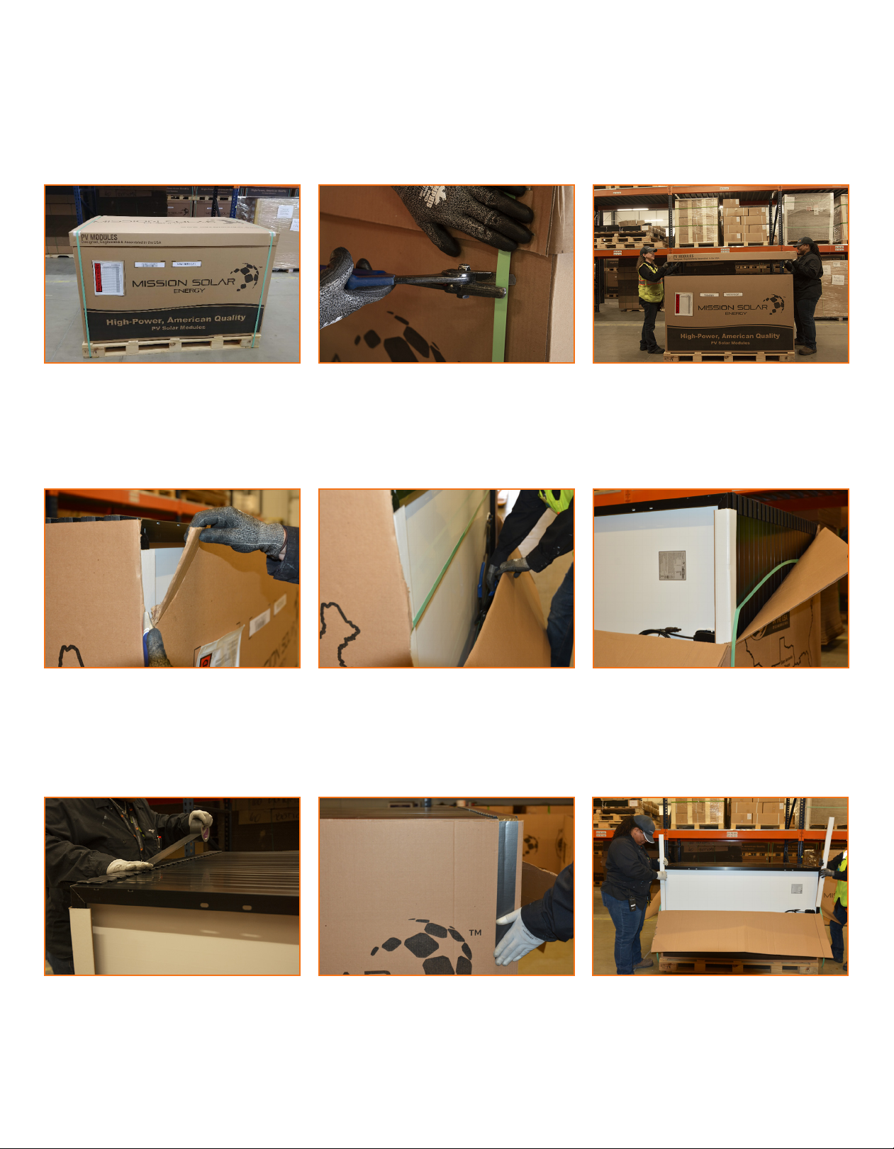
5.2 MECHANICAL
•
•
•
5.3 ELECTRICAL SHOCK HAZARD
•
•
•
•
•
•Keep connectors dry, clean, and ensure that they are in
•
•
•
See 12.2 Cleaning.
•
•
5.4 FIRE
•
•
See
9.0 Mechanical Installation
•
•
•
•
•
•
WARNING
Module Installation and User Manual - PERC and Mono Series Page 5 of 17
the inverter, have been partly or entirely destroyed, or the
Document #: P-SA2-UM-0003 Revision #: R8