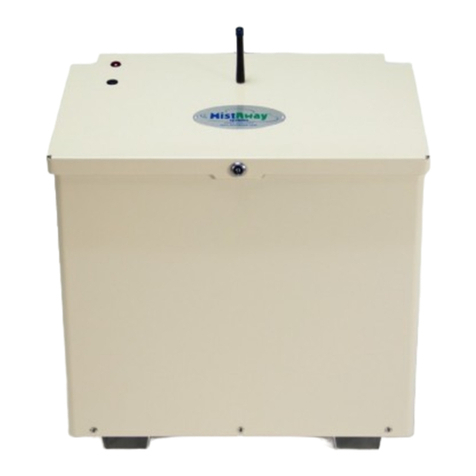
MistAway Gen 1.3 User manual

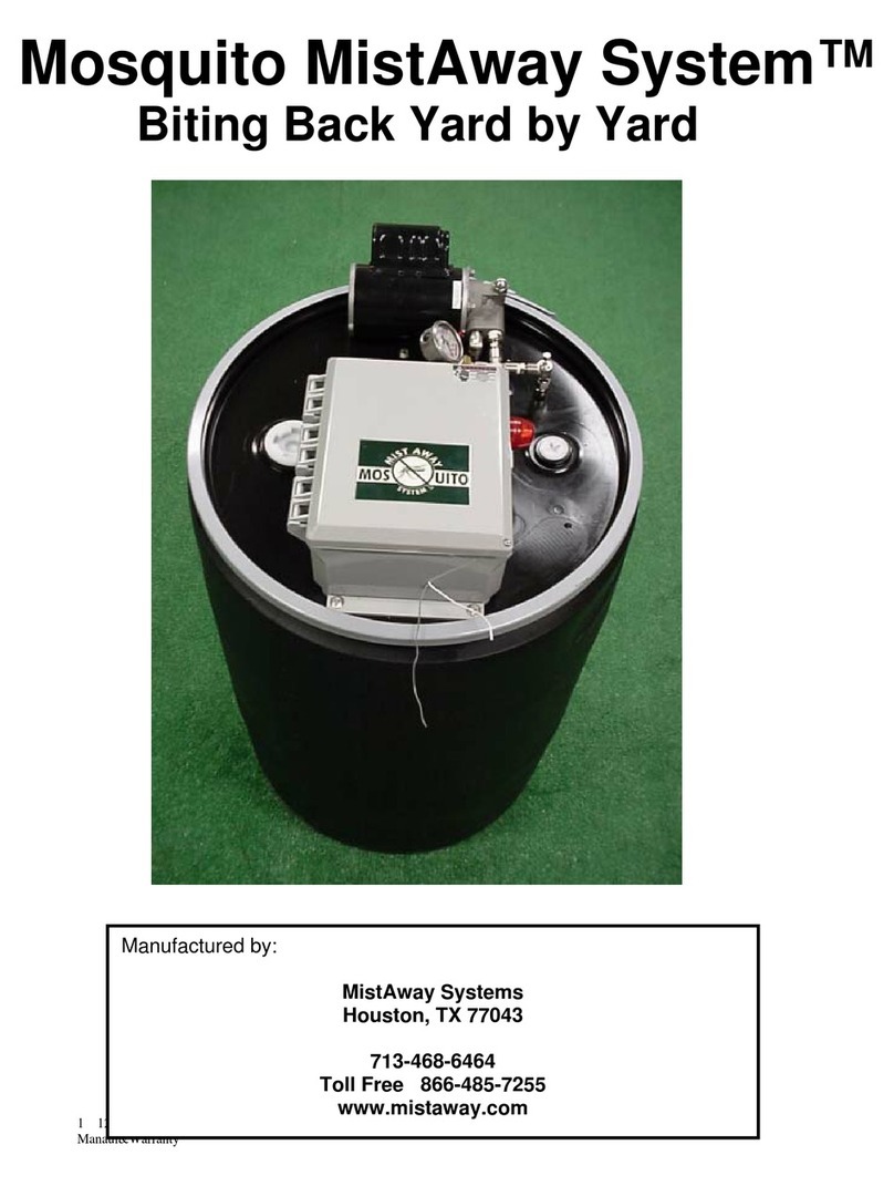
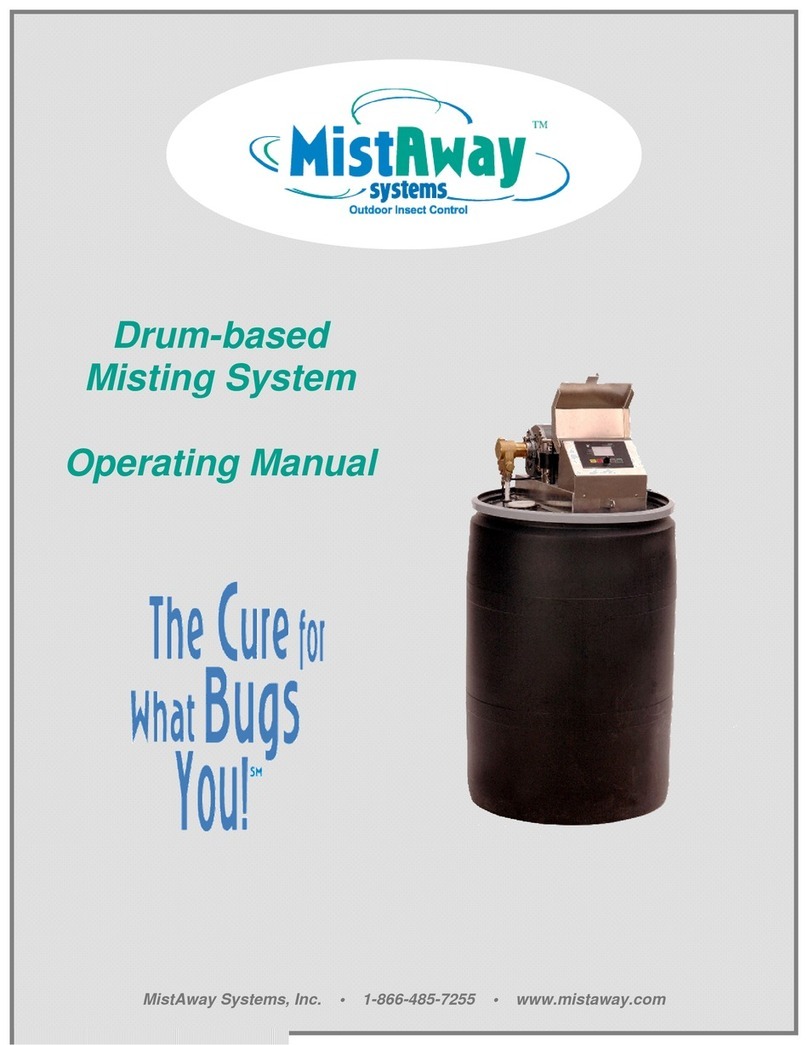
MistAway® Drum-Based Misting Unit –Gen 1.3
Operations Manual
Copyright © 2020 by MistAway® Systems, Inc.

Section 1 Important Safety Instructions
Section 2 Warranty
Section 3 Using the Controller
Section 4 Using the Remote
Section 5 Setting Up the Unit
Section 6 Managing the Insecticide
Section 7 Maintenance and Winterization
Section 8 Troubleshooting and Error Codes
Appendix A Unit Component Description
Appendix B Controller Menus
Appendix C Operating Displays
Appendix D Manual Operations
Contents
MistAway® Drum-Based Misting Unit –Gen 1.3
Operations Manual
• MistAway’s Drum-Based Misting Unit, Gen 1.3, is designed to
atomize a dilute botanical insecticide (typically contained in a 55
gallon drum) through an installed nozzle circuit to control
mosquitoes and other annoying insects.
•The capacity of the unit is dependent on the configuration of the
nozzle circuit. A practical field maximum for one zone is about
90 nozzles (not all in series) connected by 900 feet of tubing.
•The unit may be programmed to mist up to 24 times daily, with
each mist cycle having its own independent duration. A typical
program will consist of 2 to 3 mist cycles per day, each with a 45
–60 second duration, for a daily total of 90 –180 seconds.
•The unit will also mist in response to a signal from a handheld
remote transmitter for a duration programmed by the user.
Base Functionality
Optional Equipment and Functionality
MistAway® Drum-Based Misting Unit –Gen 1.3
Operations Manual
•Agitating Valve: Each mist (including remote mists) will be
preceded by an agitation cycle that will ensure thorough mixing
of the drum contents prior to misting. In addition, there is a
capability to program a once-daily agitation that is independent
of any programmed or remote mist. The agitating valve also
eliminates the possibility of a siphon emptying the drum
contents.
•Leak Detection: In the event of a leak in the misting nozzle
circuit, this option will shut-off the unit until the leak can be
repaired.
•Electronic Anti-Siphon Valve: For units without agitation,
addition of this valve eliminates the possibility of a siphon.
•Wind Sensor: Sensor input will inhibit a programmed mist if the
wind speed is higher than a user-defined limit for a 5 minute
period following the scheduled mist.
•Zone Kit: Kit will enable the unit to either independently
manage areas with two different application schedules or
effectively double the protected area that the unit would
otherwise support.
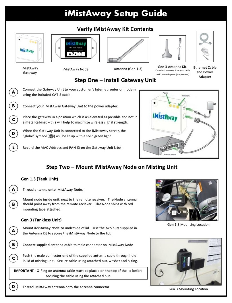
•iMistAway Module: Allows the unit to be remotely monitored
and controlled via an Internet connection.

To Protect Against Accidental Exposure to Insecticide
!WARNING DO NOT ACTIVATE SYSTEM WHEN
PEOPLE, PETS, FOOD OR FEED ARE
PRESENT!
Using the Unit
•Do not allow the unit to mist in the presence of people, pets or
food.
•Unit must be configured, installed and operated so that any
insecticide application complies with all label directions,
including application rate and prohibitions against offsite drift.
•The unit reservoir and controller should be locked.
•Unit and remote transmitter should be secured against access
by children.
•If a leak or siphon in nozzle circuit is suspected, discontinue use
of unit until it is repaired.
•Unit must never be used for cooling.
Permitted Insecticides and Handling
•Use only insecticides that are labeled for use in automated
misting systems and use only as described in the label.
• Insecticides that state “Not for use in outdoor residential misting
systems” may not be used under any circumstances.
• Once insecticide has been introduced, ensure 6” air gap
between hose and drum bung is maintained when filling.
•Insecticide label and dilution statement should be securely
attached to the unit reservoir in a weatherproof pouch.
•Strictly follow label instructions regarding storage and disposal
of insecticide and container.
Nozzle Circuit Installation:
•The nozzle circuit should be configured and installed so that
insecticide does not drift off the property.
•Nozzles should be directed to spray towards the target area and
away from swimming pools, water bodies, or eating and cooking
areas.
Section 1
Important Safety Instructions
To Protect Against Fire or Electric Shock
•Ensure unit is positioned where it is free from flooding or
exposure to irrigation system spray.
•Unit must be plugged into electrical outlet with ground fault
interrupt protection. (GFI/GFCI)
•Extension cord must not be used.
•Disconnect unit from power source if replacing components.
•Replace fuses only with those of equivalent value.
Section 1
Important Safety Instructions
Using the Unit (continued)
•The unit is not to be used by persons with reduced physical,
sensory or mental capabilities, or lack of experience and
knowledge, unless they have been given supervision or
instruction.
•Children are not to use the appliance or play around it, even
when supervised.
•The unit is not to be installed at altitudes higher than 2000
meters.

The foregoing is MSI’s only obligation and Purchaser’s exclusive remedy for breach
of warranty. Purchaser’s failure to submit a claim as provided above shall
specifically waive all claims for damages or other relief, including but not limited to
claims based on latent defects. In no event shall Purchaser be entitled to special,
direct, indirect, incidental, exemplary or consequential damages, expenses, injury,
lost profits, lost savings, business interruption, loss of business information, or any
other pecuniary loss arising out of the use of or inability to use the equipment. In
any case, MSI’s entire liability shall be limited to the amount Purchaser actually
paid for the item.
Except as modified in writing signed by both parties, this warranty is and shall
remain the complete and exclusive agreement between the parties with respect to
warranties, superseding all prior agreements, oral or written, and all other
communications between the parties relating to the subject matter of this
agreement.
Section 2
WARRANTY
MistAway Systems Inc. (MSI) warrants this Product, the MistAway Drum-Based
Misting Unit, Gen 1.3, to be free from defects in material and workmanship as
follows:
For a period of one (1) year from the date of original installation (whether or not
actual use begins on that date), MSI will repair or replace defective parts, with new
or refurbished parts, at its option, at no charge. This warranty does not include labor
or other costs incurred for diagnosing, removing, installing, shipping, servicing or
handling of either defective parts or replacement parts.
This warranty applies solely to equipment supplied by MSI and is in lieu of all other
warranties, expressed or implied. No person, agent, dealer, or distributor is
authorized or empowered to give any other warranty or to assume any other liability
on behalf of MSI
Warranty Conditions:
•This warranty is extended only to the original Purchaser and is not transferable.
•A purchase receipt or other proof of date of original purchase will be required
before warranty service is rendered.
•Installation, use, care and maintenance must be normal and in accordance with
instructions contained in the operating manual and MSI’s service information.
Failure to do so shall void this warranty.
•All claims for failure to conform to specifications or defects in material or
workmanship under this warranty must be made promptly after discovery and,
in any event, must be received by MSI not more than one year after the original
purchase date.
•MSI reserves the right to inspect the equipment prior to any decision involving a
warranty claim.
•MSI reserves the right to make warranted repairs at either the installed site or at
MSI’s location in Houston, TX. If MSI opts for repair at its own location, the
Purchaser is responsible for shipping the item to MSI’s Houston location at its
expense.
Manufacturer’s obligation under the warranty shall not apply to:
•Any equipment, which has been damaged by negligence, misuse, abuse,
neglect and/or improper adjustment, accident, vandalism, acts of God, acts of
war, whether declared or undeclared, improper application, or any other
contingency beyond the control of MSI
•Cosmetic damage
•Damage in transit
•Failures caused by products not supplied by MSI
•Failures, which result from faulty installation, set-up adjustments, improper
operation, power line surge, improper voltage supply or damage from lightning
•Any equipment that has been repaired or altered without authorization from MSI
or in a manner inconsistent with such authorization
• Any unit that has not been maintained in accordance with the operator’s
manual
•Normal wear on any item or piece of equipment
•Lost items
Section 2
WARRANTY

•Pressing Green ►button will cycle through each of four System
Modes. The ▲at the top of the display points to the active
System Mode.
1.OFF –If equipped with agitation, unit will perform a daily
agitation cycle. Otherwise it will sit idle.
2.REM –Unit will allow Remote and MANUAL MISTs, but no
AUTO MISTs. (For pre-2012 systems: displayed as ON)
3.AUTO-EVERYDAY –Misting program runs daily. This is the
most commonly used System Mode.
4.AUTO-CUSTOM –Misting program runs only on days set in
CUSTOM PGM menu.
•Pressing Red MENU/STOP button displays triangular cursor by
DAY/TIME position on left side of display. Use ▲or ▼buttons to
cycle through menu structure. Use Green ►button to select menu
item and view or change data element within that item.
•Within a menu item, the convention is that the flashing data
element can be changed with the ▲or ▼buttons. Move to the
next data element with the Green ►button.
•Exit the menu item by pressing the MENU button. The unit will
revert to previous System Mode in 3 minutes if the MENU button is
not pressed.
•Clear any error code by pressing the Red MENU/Stop button for 5
seconds. The System Mode will return to its previous state
(usually AUTO Everyday).
•To reset the controller to factory settings, unplug the unit, and hold
down MENU and the ▲button while plugging the unit back in.
Mist Cycles, remote duration and number of nozzles must be
reentered.
Section 3
Using the Controller
Section 4
Using the Remote
Note: The handheld remote transmitter must be electronically
oriented to the controller before it will operate. See
Section 5 –Setting Up the Unit.
MIST Button
•Activates a REMOTE MIST for the duration defined in the SET-
UP menu.
•An agitation cycle will precede the REMOTE MIST if the Remote
Agitation Duration (SET-UP →RAG) is set to a value greater
than 0 seconds.
•NOTE: on pre-2012 systems, agitation duration before a remote
mist is fixed at 15 seconds.
•If a Zone Kit is installed, refer to instructions included with the
zone kit to configure how the remote transmitter works.
STOP MIST Button
•The STOP MIST button stops the current operation of the unit. It
will not change the System Mode from ON or AUTO to OFF.
SKIP NEXT MIST Button
•The SKIP NEXT MIST button enables the next programmed
AUTO MIST to be skipped. The controller will display “SKIP.”
•While the unit is flashing SKIP, it will still respond to a Remote or
MANUAL MIST.
•When an AUTO MIST has been skipped, the unit will return to
the normal display, with a flashing “sunshine” icon in the lower
right corner of the display.
•You may only skip one mist at a time. That is, pushing the SKIP
NEXT MIST button multiple times will not cause multiple AUTO
MIST cycles to be skipped.
•Clear skip by holding down the ▲button on the controller for 3
seconds.

Section 5
Setting Up the Unit
•On firm level surface
•Free from flooding or sprinklers
•Near GFCI outlet –Power cord is 12 ft.
NEVER USE AN EXTENSION CORD!
•Unit requires 120V and 15 amp circuit.
Test with multimeter.
-1. Pick a Suitable
Location
0. Assemble the Unit
1. Test System and
Inspect the Nozzle
Circuit
•Verify finish kit:
•Remote transmitter
•Soft drum lid cover
•Pump suction tubing and filter
•Auto Drain Valve assembly
•Agitator J-tube and mixing eductor
•4 each –bolts, flat washers, lock
washers, nuts
•Turn the unit upside down on towel to
protect plastic housing
•Invert lid and rotate so that holes line
up with fittings.
•Insert lines into fittings:
• ½” pump suction line into pump –
ENSURE IT IS SEATED!
• ¼” Auto Drain Valve
• 3/8” Agitation J-tube
•Secure chassis to lid:
•Sequence –bolt, chassis, lid, flat
washer, lock washer nut
•Place and hand tighten all four
connections
• Tighten with 7/16” WRENCHES
•Place lid assembly on drum. Secure
with gray drum ring.
• Connect nozzle circuit to ¼’ bulkhead
fitting.
•Install optional zone kit using
instructions with the kit.
•Plug unit into outlet and confirm
controller boots up.
•Fill drum through bung on lid and set
level:
•12-15 inches of water only. DO NOT
ADD CONCENTRATE YET!
•If 125 gallon drum unit, set TNK in
SETUP Menu to 125
•Set gas gauge LEVEL in
MAINTENANCE Menu to 2 bars.
1. Test System and
Inspect the Nozzle
Circuit (cont.)
•Mount filter head to bracket with
screws.
•FILL FILTER CANISTER WITH
WATER!
•Confirm o-ring on top of the canister is
seated in groove, then screw filter
housing onto the filter head.
•Snap bracket and filter onto gray drum
ring.
• Cut and connect ¼” tubing following
direction of flow arrows:
•Use enough tubing to be able to set
filter on ground during service.
• “IN” – misting unit to filter
• “OUT” – filter to nozzle circuit
2. Install the (optional)
Nozzle Circuit Filter
•Set parameters in controller:
•Set System Mode to Auto Everyday
on home screen
•Set NOZ in SETUP Menu to nozzle
count. Set NOZ1 and NOZ2 if zone
kit.
•Set REM (remote mist duration) in
SETUP Menu to desired. 45 secs is
common.
• Put receiver in misting unit into “learn”
mode:
•LRT in SETUP Menu. Press and
hold green button.
•Countdown starts
3. Orient and Test
Handheld Remote
Transmitter
Section 5
Setting Up the Unit

Section 5
Setting Up the Unit
• Put handheld transmitter in “learn”
mode:
•Find recessed pairing button on back
of transmitter.
•Use paperclip to press and quickly
release button. DO NOT HOLD
PAIRING BUTTON DOWN!
•Blue LED will flash several times
• Controller will display “DONE”
•Press MIST on handheld to complete
pairing.
•Test remote by pressing MIST. Stop
cycle by pressing STOP MIST.
3. Orient and Test
Handheld Remote
Transmitter (cont.)
•Confirm the unit has leak detection
option installed. LD in DATA Menu will
be ON.
•Press MIST on handheld transmitter
and allow for a complete remote mist
cycle.
•If controller displays ERR3, there is
probably a leak in the nozzle circuit.
•Clear the error by pressing and holding
the Red Stop button and run another
mist to confirm.
4. Test Leak Detection
•Unapproved concentrates may
damage the system or may not be
legal to apply through the system.
Make sure concentrate is in Gen 1.3
Approved Insecticides (mistaway.com)
•Calculate required volume of
concentrate:
•Refer to label or link for dosing
instructions.
•Use Dosing and Days to Empty
Calculator (mistaway.com)
•Use funnel to add concentrate to drum
through bung on lid
•Apply adhesive-backed label supplied
with concentrate to side of drum.
5. Add Concentrate,
Top Off Drum, Set
Level to FULL
Section 5
Setting Up the Unit
•Fill drum with water to 3 inches from
top. Do not overfill. Maintain 6” air gap
between hose and fluid level.
•Set gas gauge LEVEL in Maintenance
Menu to full.
5. Add Concentrate,
Top Off Drum, Set
Level to Full (cont.)
•Confirm day and time on home screen
are correct. If not, reset in DAY/TIME
Menu.
•Set mist duration and time for each
cycle in CYCLES Menu. 24 possible
daily mist cycles.
•A common program is:
•Morning: around 7:00 am for 45
seconds (after sprinkler system has
run)
•Dusk: around 7:00 pm for 45
seconds
•Night: around 11:00 pm for 45
seconds
•You may need to set other parameters
in the SET-UP Menu (e.g. if you are
installing a wind sensor.) Find a
complete list at Appendix B, Controller
Menus.
6. Set Mist Cycles
•Confirm System Mode set to Auto
Everyday on home screen.
•Put the waterproof cover over the unit,
fitting the elastic under the lip at the
edge of the drum.
7. Prepare unit for
operation

Section 6
Managing the Insecticide
•Use only insecticides that are labeled for use in
automated misting systems and use only as described on
the label. Insecticides that state “Not for use in outdoor
residential misting systems” may not be used under any
circumstances.
•There are only a few insecticide formulations that contain label
language specific for use in automated misting systems.
•The active ingredients found in these formulations are either
natural pyrethrins or permethrin, which is a closely related
synthetic. They also contain a synergist, piperonyl butoxide,
which makes them more effective than they would otherwise
be.
•These formulations have been designed for misting and are
suitable in MistAway’s systems because 1) they are water-
based and contain only trace amounts of hydrocarbons, 2)
they have been engineered to disperse evenly throughout the
batch tank or drum when diluted with water, and 3) they have
been formulated to avoid or minimize plant burn.
•There are also a small number of insecticide formulations that
are applied in misting systems that are exempt from
registration with the U.S. EPA.
•Generally, the ingredients found in these formulations are
essential oils from plants. In order to dilute and disperse them
in a volume of water, an emulsifying agent must be added.
•Be aware that these concentrates are very chemically
aggressive, particularly to plastics. Their use in misting
systems significantly increase maintenance requirements and
maintenance frequency.
Visit www.mistaway.com for a list of approved insecticides and
mixing guidance.
Conventional Insecticide Formulations
Exempt or “Green” Insecticide Formulations
Section 6
Managing the Insecticide
•It is important to note that there are differences of opinion among
misting professionals as to what schedule and duration is
optimal in any given circumstance. These reflect differences in
factors such as relative mosquito pressure, species and activity,
conducive conditions, etc.
•While these differences do exist, a common schedule is
comprised of two scheduled mists per day:
•A mist of 45 seconds in the hours around dawn (after the
sprinkler system has finished).
•Another mist of 45 seconds in the time around dusk.
•A third mist of 45 seconds sometime in the hours between
9:00 PM and 1:00 AM.
•In this common schedule, the automated mists are timed to
occur when there is unlikely to be activity on the property. Their
timing also avoids afternoon winds and the daylight activity of
beneficial insects like bees and butterflies.
Mist Schedule and Duration
•Use only insecticides that are labeled for use in automated
misting systems and strictly follow label instructions in adding
insecticide to the drum:
•Example: A 5% pyrethrin formulation, contains label language
for use in Residential Backyards to “Mix 64 fl. Oz of concentrate
in 55 gallons of water to yield a solution of 0.046% Pyrethrins
and 0.23% Piperonyl Butoxide.”
•The insecticide label will contain both recommended and
maximum concentrations. It is against regulations to mix the
insecticide to a concentration that exceeds the stated limit.
•Concentrations less than recommended on the label are
permissible, although there is a threshold below which the
material will not be effective.
Adding Insecticide to Gen 1.3

Section 6
Managing the Insecticide
The Gen 1.3 controller stores a “virtual volume” representing the amount
of dilute insecticide remaining in the drum. Each time the unit mists, this
“virtual volume” is reduced by a calculated estimate of the volume of dilute
insecticide that was misted through the nozzle circuit. When the “virtual
volume” equals 0, EMP (Empty) is displayed on the controller, and it is
time to replenish the insecticide.
•Calculate required volume of concentrate:
oSelect a concentrate from the list of
https://www.mistaway.com/techselfhelparticles/gen-1-3-approved-
insecticides/
oRemove drum cover
oRemove cap from drum bung
oUse a yardstick to measure inches of remaining solution and note
it.
oCalculate required volume of concentrate and water (in inches
from bottom of drum) using the calculator at
https://www.mistaway.com/techselfhelparticles/dosing-and-days-
to-empty-calculators/
oIf you are using an approved concentrate other than ones
presented in the calculator, you can find the information required
by the calculator –the concentration of active ingredients in the
formulation and target concentration in the mist –in the list of Gen
1.3 approved insecticides referenced above.
•Replenish drum with water and concentrate:
oFill the drum with a few inches of water from a garden hose, being
careful to maintain an air gap of 6” between the tip of the hose and
the fluid in the drum.
oMeasure concentrate and use a funnel to add it through the bung.
oContinue filling the drum with water to the desired level –
maintaining the 6” air gap. To avoid foaming and possible
equipment damage, stop filling when the fluid level is 4” from the
top.
oReplace cap on drum bung.
oEnsure concentrate label in waterproof envelope is affixed to the
side of the drum and visible.
oDispose of the empty bottle strictly following label instructions or
regulations regarding disposal.
oRecord type and volume of concentrate added in log.
Replenishing Insecticide Concentrate in Gen 1.3
Section 6
Managing the Insecticide
•Reset level indicator in the controller to Full (8 bars):
oNavigate to MAINTENANCE Menu, scroll to LEVEL. Press
Green ►button.
oUse ▲button to set level to full (8 bars)
•Prepare unit for operation:
oConfirm AUTO Cycle times and durations.
oConfirm Remote Mist duration
oConfirm operating Mode –usually AUTO Everyday
oClose plastic lid and secure waterproof cover.
Replenishing Insecticide Concentrate in Gen 1.3
•There are a number of factors that influence consumption of
the insecticide and timing for replenishment:
•Number of nozzles installed
•Minutes of scheduled misting per day
•Number and duration of remote mists
•Volume of the drum
•To estimate the replenishment frequency for the system, use
the calculator at
https://www.mistaway.com/techselfhelparticles/dosing-and-
days-to-empty-calculators/
Replenishment Frequency

Section 8
Troubleshooting and Error Codes
•Remove any debris that has collected on drum lid to prevent it
from falling into the drum and fouling the intake filter or nozzle
circuit.
•Clean filter on pump intake line. Remove filter from intake line.
Use wire brush and hose to remove debris.
1. Flush pump, agitation valve (if equipped) and nozzle circuit
with clean water:
•Fill 5-gallon bucket with fresh water and position next to unit.
•Lift drum lid (with mounted assembly) from drum and
rotate/reposition so that pump intake line is submerged
inside 5-gallon bucket.
2. Activate a dry Manual Mist cycle and lift left side of unit to clear
remaining water.
•Remove intake line from bucket, disconnect nozzle circuit
from unit.
•Activate a dry (i.e., suction line not in any fluid) Manual Mist
cycle.
•IMPORTANT! While unit is running dry, lift left side of unit
about 6 inches to clear water from agitation valve.
•Reposition drum lid and assembly back on drum.
3. Clear water from pressure gauge and leak detection flow
meter (if equipped).
•Lift controller from well in shroud.
•Disconnect tubing to pressure gauge and from inlet/left side
of flow meter and tilt drum to left, allowing water to drain.
Reconnect tubing.
•Replace controller in well.
4. Clear water from nozzle circuit filter (if equipped).
5. Unplug unit from power, wrap power cord around
assembly, replace drum cover.
6. Purge water remaining in nozzle circuit with compressed
air.
a. Remove the tip from the last nozzle on the end of each
run.
b. Use portable air compressor with adapter (MistAway
Part # 20052) to purge fluid from nozzle circuit.
Section 7
Maintenance and Winterization
With Each Refill
Each Year/Winterization*
See https://www.mistaway.com/category/gen-1-3-troubleshooting/
for troubleshooting the following issues:
•ERR2 –Flowmeter value is zero after MIST
•ERR 3 –MIST volume greater than expected
•Unit not misting automatically
•Unit not responding to command from handheld remote
transmitter
•Controller displays EMP and unit will not mist
•Controller displays NOZ00, SKIP, ERR# or SUS and unit will not
mist
•Controller displays MIST, but nozzles not misting
•Displayed tank level does not match actual tank level
•Controller display is blank
•Zone Kit problems:
oSystem mists from Zone 1 when it should be misting from
Zone 2
oSystem mists from both zones at the same time
oSystem does not mist from either zone

Components –Mounted to Chassis on Drum Lid
Components –Inside Drum
Appendix A
Unit Component Description
•Digital Controller –accepts user input, displays unit operating
mode and status, controls electromechanical components.
•Remote Receiver & Antenna –receives signal from handheld
remote transmitter
•Pump & Motor –atomizes drum contents through nozzle circuit.
Pump pressure typically set to 240 psi.
•Agitating Valve (optional) –One path through the valve routes
fluid to the nozzle circuit. The other path recirculates fluid in the
drum through j-tube mixing assembly.
•Plastic Housing & Cover –protects components from the
elements. The cover may be locked to the housing to secure
access to the controller. The housing contains ports to the
nozzle circuit tubing as well as to an optional Zone Kit. On units
with an agitating valve, a pressure gauge is mounted into the
plastic housing.
•Pump Intake Line and Filter –Pump intake positioned near
bottom of drum. Filter ensures debris is not drawn into pump
and nozzle circuit.
•J-tube Mixing Assembly (on units with optional Agitating
Valve) –To ensure thorough mixing, during agitation, fluid is
pushed through a j-shaped tube assembly at the bottom of the
drum.
•Auto-Drain Valve –ensures rapid increase in nozzle circuit
pressure on pump startup and rapid decrease on shutdown.
•Remote Transmitter –3-button remote enables the user to start
a mist, stop a mist and skip the next scheduled mist.
•Unit Cover –Weatherproof fabric cover provides protection of
the unit from the elements.
Other Components
The operations of the Gen 1.3 are managed by a digital controller
and a number of electro-mechanical components. Information
about mist schedules, duration, and agitating the insecticide are
entered into the controller by the user.
Schematic
Appendix A
Unit Component Description
Pump
Intake
& Filter
Auto
Drain
Valve
Agitation
Valve 55 gallon
drum
Digital Controller
Remote
Receiver
Antenna
Motor Pump
Nozzle
Circuit
Mixing
Eductor

MAINTENANCE Menu
Appendix B
Controller Menus
LEVEL Set the tank level in the controller display from 1 to 8 bars.
In operation, the indicated level will decrease as insecticide
is misted. Press Green ►button, then ▲and ▼buttons to
set.
INS Inspect Nozzle Circuit. Runs pump for 5 minutes. Hold
Green ►button for 3 seconds to trigger. If Zone Kit
installed, separate inspection menus, INS1 and INS2.
Appendix B
Controller Menus
Set the Day of the Week and the Time of Day
and Daylight Savings Time switch.
DAY/TIME Menu
Configure the mist time and duration of each of
24 possible Auto Mist Cycles (Each with unique
duration and time of day.)
CYCLES Menu
Configures the days of the week for Auto
Misting in the AUTO-CUSTOM PGM
mode. (Turn each day OFF or ON.)
CUSTOM PGM Menu
REM Set the duration for mists triggered by the remote
transmitter. (Values from OFF to 120 seconds)
LRN/LRT Program unit to recognize remote handheld transmitter.
See Section 5 –Setting Up the Unit.
MAN Set the duration for mists triggered by a Manual Mist
(pressing ▲and ▼buttons simultaneously.)
NOZ Set the Number of nozzles in the circuit attached to the
unit.
AGT Set duration in seconds of agitation prior to programmed
mists and set time of once daily off-cycle agitation. On
units without an agitating valve, the duration should be set
to 0.
RAG Set duration in seconds of agitation cycle prior to a remote
mist cycle.
TNK Set reservoir size in gallons (5 –995)
NFR Target flow rate of average nozzle in circuit, in milliliters
per minute. Used in tank level indicator, Empty shut-off
and leak detection calculations. Default is 40 mL/min.
TOL Error tolerance for nozzle circuit flow rate. Controls
sensitivity of leak detection. (Set as per NFR).
SEN Turn (optional) wind sensor ON or OFF
WND Set max wind speed (above which wind sensor reading
inhibits mist).
ALT This feature is not currently used. ALT should be set to 0.
SET-UP Menu
For systems with a zone kit, there are other menu items –NZ1, NZ2,
RMZ, MNZ, ZNC, ZN1 and ZN2 –that are explained in the
instructions referenced in the zone kit hardware.
DATA Menu
(Items marked ** are for units equipped with leak detection)
TMC Total Mist Cycles since last reset.*
TMM Total Mist Minutes since last reset.*
MMC Manual Mist Cycles since last reset.*
RMC Remote Mist Cycles since last reset.*
TMH Total Mist Hours on unit. May not be reset.
SPD Wind speed as read by sensor
FL** Actual volume pumped out of tank during last mist (mL).
AFR** Actual average flow rate of nozzle in circuit, based on
volume of fluid discharged during last mist cycle.
TF** Calculated target volume in milliliters (mL) of last mist.
Target Volume = (Mist Duration in seconds) * (Number of
Nozzles) * (Nozzle Flow Rate NFR) / 60.
HLD Duration that Agitating Valve or Anti-Siphon Valve remains
open to nozzle circuit after pump shuts off. Used to control
“at-rest” pressure maintained in circuit. (Set as per NFR).
FM Flow meter pulses per gallon –factory configuration only
LGW Pair iMist2 gateway with iMist2-ready receiver
There are additional elements in the Data Menu –PANID, NR, FR,
M, P, PL#, R, S, N ### - used to enable and troubleshoot iMistAway
internet monitoring and management functionality.

Appendix D
Manual Operations
•STOP - Pressing Red MENU/STOP button will immediately stop
any current operation of the unit but will not change the System
Mode from AUTO to OFF. (To change the System Mode to
OFF, use the Green ►Auto/On/OFF button to cycle through
each of four System Modes. The ▲at the top of the display
points to the active System Mode.
•MANUAL MIST - Pressing the ▲and ▼arrows simultaneously
(2 seconds) will activate a mist cycle for the duration
programmed in the SET-UP menu.
•INSPECT - Unit will mist for 5 minutes or until stopped.
Navigate to INS in the MAINTENANCE Menu. Press the Green
►button for 5 seconds.
There are a number of operations that can be performed while
standing at the unit:
AGT Unit is agitating contents of drum.
EMP Empty. Unit has calculated zero remaining volume in tank.
HOLD Anti-siphon or agitation valve is being held open at end of
mist cycle to allow pressure in nozzle circuit to decay and
close nozzles quickly.
INS Unit is in Inspection Mode and will mist for 20 minutes or
until stopped.
MST Unit is misting.
NOZ00 Unit stopped operating because the number of nozzles is set
to 0. Clear by pressing Red STOP button for 5 seconds.
ERR2** Flow meter value is zero after MIST. See Section 7,
Troubleshooting and Error Codes. Clear by pressing Red
STOP button for 5 seconds.
ERR3** MIST volume greater than expected. See Section 7,
Troubleshooting and Error Codes. Clear by pressing Red
STOP button for 5 seconds.
SKIP Unit will skip next programmed mist, having received signal
from remote transmitter to SKIP NEXT MIST. Clear by
holding down the ▲arrow button for 3 seconds.
SUS Wind sensor reading higher than user-set max and is
suspending programmed mist.
The previous mist was skipped because SKIP NEXT MIST
was triggered by the remote or the wind sensor blocked an
Auto Mist.
Appendix C
Operating Displays
Operating Displays
(Items marked ** are for units equipped with leak detection)
Other MistAway Insect Control Equipment manuals