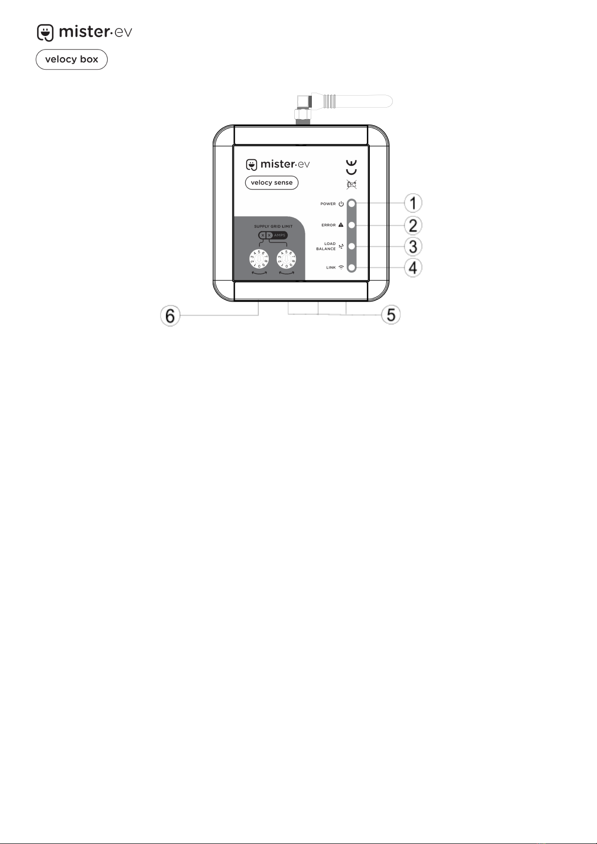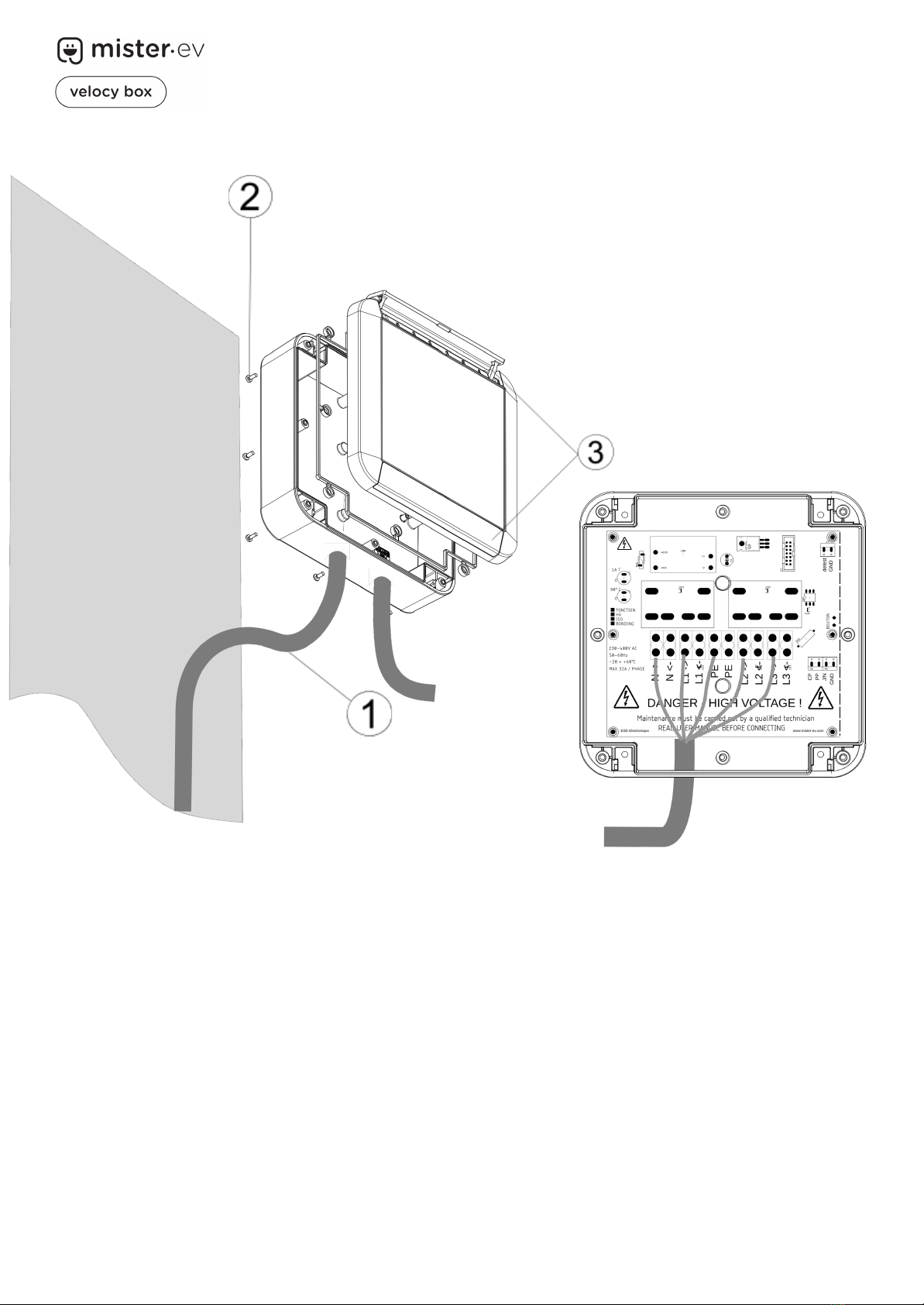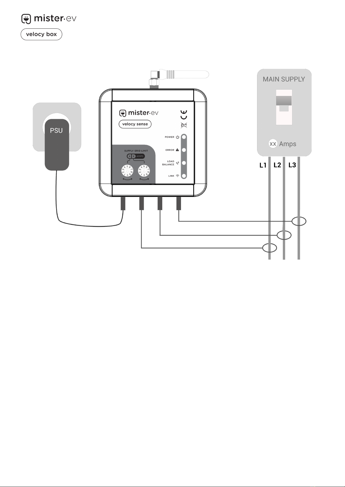
User Manual / Technical Manual v1.2
INTRODUCTION
Thank you for purchasing the Velocy BOX! We hope it will give you complete satisfaction
and that its advanced features will be of great use to you.
This user manual will help you familarise yourself with your Velocy BOX and ensure you
take full advantage of all its features.
Keep it in a safe place for future reference.
SAFETY INSTRUCTIONS
The Velocy BOX is an alternating current (AC) charging device designed to be installed on
a fixed point and connected to a permanent power supply.
The device is designed for indoor or outdoor use and must be mounted on a vertical flat
surface (wall or post).
The Velocy BOX has been designed with your safety in mind. However, to avoid any risk of
injury or death, please observe the following points:
➔The device must be installed, repaired and maintained by qualified personnel only.
➔The fitter, servicer or maintenance technician must have skills and knowledge in the
construction, installation and operation of electrical equipment and have received
safety training on the hazards associated with the installation of electric vehicle
charging equipment.
➔All local regulations must be observed when installing, repairing and maintaining
this appliance.
➔This device must not be installed if any damage is found when it is unpacked.
➔This device must not be used by persons with reduced physical, sensory or mental
capabilities without the supervision of a person responsible for their safety.
➔This device is designed for use with an IEC-62196 compliant vehicle. Never use it
for any other purpose.
➔The use of adapters, extension leads or conversion cables on this appliance is
prohibited.
Failure to comply with the safety and installation instructions in this manual may invalidate
the manufacturer's warranty.